EP0943232B1 - Behälter mit Förderwalze - Google Patents
Behälter mit Förderwalze Download PDFInfo
- Publication number
- EP0943232B1 EP0943232B1 EP19990460016 EP99460016A EP0943232B1 EP 0943232 B1 EP0943232 B1 EP 0943232B1 EP 19990460016 EP19990460016 EP 19990460016 EP 99460016 A EP99460016 A EP 99460016A EP 0943232 B1 EP0943232 B1 EP 0943232B1
- Authority
- EP
- European Patent Office
- Prior art keywords
- bucket
- arm
- rotor
- actuator
- motor
- Prior art date
- Legal status (The legal status is an assumption and is not a legal conclusion. Google has not performed a legal analysis and makes no representation as to the accuracy of the status listed.)
- Expired - Lifetime
Links
- 239000007788 liquid Substances 0.000 claims description 3
- 230000000630 rising effect Effects 0.000 claims 1
- 239000000463 material Substances 0.000 description 8
- 239000012530 fluid Substances 0.000 description 3
- 230000000694 effects Effects 0.000 description 2
- 230000002093 peripheral effect Effects 0.000 description 2
- 238000009412 basement excavation Methods 0.000 description 1
- 239000000470 constituent Substances 0.000 description 1
- 238000010586 diagram Methods 0.000 description 1
- 239000004459 forage Substances 0.000 description 1
- 230000007935 neutral effect Effects 0.000 description 1
- 230000000149 penetrating effect Effects 0.000 description 1
- 230000001105 regulatory effect Effects 0.000 description 1
- 238000005070 sampling Methods 0.000 description 1
- 239000004460 silage Substances 0.000 description 1
- 238000011144 upstream manufacturing Methods 0.000 description 1
Images



Classifications
-
- A—HUMAN NECESSITIES
- A01—AGRICULTURE; FORESTRY; ANIMAL HUSBANDRY; HUNTING; TRAPPING; FISHING
- A01F—PROCESSING OF HARVESTED PRODUCE; HAY OR STRAW PRESSES; DEVICES FOR STORING AGRICULTURAL OR HORTICULTURAL PRODUCE
- A01F25/00—Storing agricultural or horticultural produce; Hanging-up harvested fruit
- A01F25/16—Arrangements in forage silos
- A01F25/20—Unloading arrangements
- A01F25/2027—Unloading arrangements for trench silos
-
- A—HUMAN NECESSITIES
- A01—AGRICULTURE; FORESTRY; ANIMAL HUSBANDRY; HUNTING; TRAPPING; FISHING
- A01F—PROCESSING OF HARVESTED PRODUCE; HAY OR STRAW PRESSES; DEVICES FOR STORING AGRICULTURAL OR HORTICULTURAL PRODUCE
- A01F25/00—Storing agricultural or horticultural produce; Hanging-up harvested fruit
- A01F25/16—Arrangements in forage silos
- A01F25/20—Unloading arrangements
- A01F25/2027—Unloading arrangements for trench silos
- A01F2025/2063—Machinery for shredding successive parallel layers of material in a trench silo
-
- A—HUMAN NECESSITIES
- A01—AGRICULTURE; FORESTRY; ANIMAL HUSBANDRY; HUNTING; TRAPPING; FISHING
- A01F—PROCESSING OF HARVESTED PRODUCE; HAY OR STRAW PRESSES; DEVICES FOR STORING AGRICULTURAL OR HORTICULTURAL PRODUCE
- A01F25/00—Storing agricultural or horticultural produce; Hanging-up harvested fruit
- A01F25/16—Arrangements in forage silos
- A01F25/20—Unloading arrangements
- A01F25/2027—Unloading arrangements for trench silos
- A01F2025/2072—Scoops with an extracting tool mounted inside or in the vicinity of said scoop
-
- A—HUMAN NECESSITIES
- A01—AGRICULTURE; FORESTRY; ANIMAL HUSBANDRY; HUNTING; TRAPPING; FISHING
- A01F—PROCESSING OF HARVESTED PRODUCE; HAY OR STRAW PRESSES; DEVICES FOR STORING AGRICULTURAL OR HORTICULTURAL PRODUCE
- A01F25/00—Storing agricultural or horticultural produce; Hanging-up harvested fruit
- A01F25/16—Arrangements in forage silos
- A01F25/20—Unloading arrangements
- A01F25/2027—Unloading arrangements for trench silos
- A01F2025/2081—Hydraulic features of the trench silos unloading devices, e.g. hydraulic circuits
Definitions
- the present invention relates to a drawing bucket intended to equip a agricultural loader, of the type comprising a rotary rotor which is driven by a motor hydraulic and is carried by a pivoting arm articulated in the upper part of the bucket, this arm being likely to lower in the direction of the bucket inlet opening under the action a hydraulic cylinder.
- This type of bucket is commonly mounted on a front loader, and used for taking from a mass of material, for example silage, a certain amount of product.
- the rotor is a drum, of horizontal axis, provided with peripheral teeth allowing it to "bite” into the product; the materials thus torn from the mass are pushed back inside the bucket, gradually, as you work, thanks to the articulated mounting of the rotor and its downward movement.
- the arm supporting the rotor is pivoted by means of a hydraulic distributor, independently of the rotation of the rotor.
- a hydraulic distributor independently of the rotation of the rotor.
- the invention aims to solve this problem by proposing a bucket of the type aforementioned with which the progression of the arm supporting the rotor is controlled automatically to accommodate the torque developed by the hydraulic motor which drives the rotor in rotation.
- said motor is hydraulically connected to the cylinder via a regulation valve adapted to slow down automatically lowering the arm in the event of an increase in the supply pressure of the engine.
- the jack is double-acting and one of its chambers is supplied with high-pressure hydraulic fluid, while the other is connected to the return low pressure to lower the arm, the slowing down of this descent being achieved by throttling the flow on the return duct.
- the hydraulic connection between said cylinder and said motor comprises a non-return valve capable of ensuring a supply at full cylinder flow when the arm is raised.
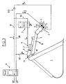
- FIG. 1 is partially shown an agricultural tractor T equipped at the front with a front loader with stretcher B capable of being raised or lowered, by pivoting around a transverse axis X by means of a pair of cylinders VL called “lifting" (of which only one is visible in this side view).
- a hinged tool holder frame C At the front of the stretcher B is fixed a hinged tool holder frame C , the movements of which are controlled by a pair of so-called “tipping" VN jacks.
- a bucket 1 On the tool holder frame C is mounted a bucket 1 according to the invention, of usual form, the opening 10 of which faces forward and upward.
- a pivoting arm 3 directed towards the exterior with respect to the opening 10, articulated around an axis 30.
- arm actually means a two-part arm, that is to say a pair of parallel arms, only one being visible in the figure, since it is a side view on which the two parts overlap.
- this "arm” supports a rotary rotor 2, usual type, with peripheral teeth.
- the rotor axis is arranged horizontally and transversely, its ends being suitably guided in rotation, each in one of the two constituent parts of the arm 3, the rotor being located between these two parts.
- AT one end of the shaft is fitted with a hydraulic motor 5, fixed against the part corresponding.
- the movement of the arm 3 is controlled by a hydraulic cylinder 4, of which the body is attached to the bucket, and the rod to the arm.
- FIG. 1 illustrates a drawing operation of materials, for example fodder F.
- materials for example fodder F.
- the latter excavates an excavation in the mass of fodder, taking therefrom product which is brought along as the sampling takes place inside the bucket by means of the descent of the rotor.
- the operator located in the tractor cabin, acts on the VL and VN cylinders so as to control the height and tilt positions of the bucket, as well as the cylinder 4 to lower or raise the rotor.
- the rotor is hidden from it.
- FIG. 1 represents the hydraulic control circuit of the motor 5 and cylinder 4, circuit which constitutes the fundamental element of the invention.
- the cylinder 4 is double-acting.
- the hydraulic fluid supply lines from the high-pressure source HP , and back to the tank - low-pressure BP - are connected to a hydraulic control distributor 8, which is actuated by the operator at using an appropriate body, such as a lever.
- the distributor 8 is in three positions. In the middle position (illustrated in Figure 1), it isolates the hydraulic circuit.
- the value of the high pressure is between 150 and 200 bar (between 1.5 and 2.10 7 Pa), while the low pressure is atmospheric pressure.
- Distributor 8 leave two hydraulic conduits 80, 81, which are connected to the motor 5 for driving the rotor. One of them, the conduit 81, carries a non-return valve 810 which imposes on the motor a single direction of rotation A.
- the rotor turns only if the duct 80 is connected to high pressure, and the leads 81 to low pressure.
- the large chamber 6 of the jack 4 is connected, by a branch 60, to the conduit 80.
- valve regulation 9 Its small chamber 7 is connected, by a conduit 70, to a valve regulation 9.
- the latter is connected by a branch 90 to the conduit 81 already mentioned. This connection is located downstream of the valve 810 (relative to the motor 5, located upstream on return line 81).
- the regulating valve 9 is preferably of the proportional type. Its state is controlled by the pressure of the liquid passing through the conduit 80, as shown by the dashed line 800 which connects it to it.
- valve 9 When the pressure in the duct 80 is low, the valve 9 allows the free passage of the liquid from line 70 to line 90, or vice versa.
- This system operates as described below.
- the distributor 8 In normal operation, which corresponds to the representation of FIG. 3, the distributor 8 is open, in a position which corresponds to the connection of the conduit 80 at high pressure, and of the conduit 81 at low pressure, the direction of movement hydraulic fluid in the circuit being symbolized by the arrows h, i, j, k, and l.
- the rotor 2 is rotated along A, its motor 5 being properly supplied by the line 80 (arrow j ), with return to the tank by the line 81 (arrow k ).
- the chamber 6 of the jack 4 is supplied (arrow h ), while the chamber 7 is empty (arrow i ); the jack is therefore extended, causing the lowering of the arm 3 and of the rotor which it supports (arrow B).
- the rotor occupies position 2 'shown in phantom fine in figure 2.
- the bucket is then filled with materials.
- the braking of the engine generates an increase in the torque causing an overpressure in the supply duct 80, overpressure which is reflected in the valve 9 by the collection line 800.
- the emptying line 70-90 of the chamber 7 of the cylinder 4 is thus subjected to a constriction.
- the flow i 'in this line is therefore reduced, which thwarts, and brakes, the extension of the jack 4 as well as, correspondingly, the downward movement of the arm 3.
- the valve 9 being of the proportional, or approximately proportional, type. the descent of the arm is all the more slowed down as the engine struggles.
- the system is self-regulating (servo).
Landscapes
- Life Sciences & Earth Sciences (AREA)
- Environmental Sciences (AREA)
- Fluid-Pressure Circuits (AREA)
- Shovels (AREA)
- Operation Control Of Excavators (AREA)
Claims (3)
- Entleerungs-Baggereimer, der dafür bestimmt ist. in einer landwirtschaftlichen Beladevorrichtung eingebaut zu sein, und der einen Drehrotor (2) aufweist, der von einem hydraulischen Motor (5) angetrieben und von einem Schwenkarm (3) getragen ist, der am oberen Bereich des Baggereimers (1) gelenkig angebracht ist, wobei sich dieser Arm (3) in Richtung der Eingangsöffnung (10) des Baggereimers (1) unter der Wirkung eines hydraulischen Stellantriebs (4) absenken kann, dadurch gekennzeichnet, dass der Motor (5) hydraulisch an den Stellantrieb (4) mittels eines Regelventils (9) angeschlossen ist, das dafür eingerichtet ist, das Absenken des Armes (3) im Falle des Anstiegs des Versorgungsdrucks des Motors (5) automatisch zu verlangsamen.
- Baggereimer gemäß Anspruch 1, dadurch gekennzeichnet, dass der Stellantrieb (4) doppeltwirkend ausgebildet ist und eine (6) seiner Kammern mit hydraulischer Hochdruckflüssigkeit gespeist wird, während die andere (7) Kammer an den Niederdruckrücklauf (81) angeschlossen ist, um den Arm (3) absenken zu lassen, wobei die Verlangsamung dieses Absenkens durch Drosselung der Durchsatzleistung in der Rücklaufleitung (70-90) durchgeführt wird.
- Baggereimer gemäß Anspruch 2, dadurch gekennzeichnet, dass der hydraulische Anschluß zwischen dem Stellantrieb (4) und dem Motor (5) ein Rückschlagventil (810) aufweist, das dazu in der Lage ist, eine Versorgung mit voller Durchsatzleistung des Stellantriebs (4) während des erneuten Anhebens des Armes (3) sicherzustellen.
Applications Claiming Priority (2)
| Application Number | Priority Date | Filing Date | Title |
|---|---|---|---|
| FR9803562 | 1998-03-18 | ||
| FR9803562A FR2776164B1 (fr) | 1998-03-18 | 1998-03-18 | Godet a rotor |
Publications (2)
| Publication Number | Publication Date |
|---|---|
| EP0943232A1 EP0943232A1 (de) | 1999-09-22 |
| EP0943232B1 true EP0943232B1 (de) | 2003-04-02 |
Family
ID=9524390
Family Applications (1)
| Application Number | Title | Priority Date | Filing Date |
|---|---|---|---|
| EP19990460016 Expired - Lifetime EP0943232B1 (de) | 1998-03-18 | 1999-03-03 | Behälter mit Förderwalze |
Country Status (4)
| Country | Link |
|---|---|
| EP (1) | EP0943232B1 (de) |
| DE (1) | DE69906409T2 (de) |
| ES (1) | ES2192027T3 (de) |
| FR (1) | FR2776164B1 (de) |
Families Citing this family (4)
| Publication number | Priority date | Publication date | Assignee | Title |
|---|---|---|---|---|
| FR2800234B1 (fr) * | 1999-11-03 | 2006-04-28 | Desvoys Et Fils | Dispositif de commande electro-hydraulique pour benne distributrice de fourrage |
| EP1292180B1 (de) * | 2000-06-22 | 2004-09-15 | Unifast S.r.l. | Wagen zum mischen von futter |
| EP1563725A1 (de) * | 2004-02-13 | 2005-08-17 | Cornelis Hendricus Liet | Vorrichtung zur Mischung von Futter |
| FR2935586B1 (fr) * | 2008-09-09 | 2010-09-17 | Emily Ets | Godet de desilage |
Family Cites Families (4)
| Publication number | Priority date | Publication date | Assignee | Title |
|---|---|---|---|---|
| US3985305A (en) * | 1975-05-07 | 1976-10-12 | Koehring Company | Silage unloader |
| EP0082313A1 (de) * | 1981-11-20 | 1983-06-29 | B. Strautmann & Söhne GmbH & Co. | Vorrichtung zur Entnahme von Corn-Cobmix aus einem Flachsilo |
| ATE215305T1 (de) * | 1996-07-08 | 2002-04-15 | Josef Altenbuchner | Fahrsiloentnahmegerät |
| FR2754671B3 (fr) * | 1996-10-23 | 1998-12-18 | Deboffles Regis Pierre Arthur | Dispositif pour prelever et charger des produits ensiles |
-
1998
- 1998-03-18 FR FR9803562A patent/FR2776164B1/fr not_active Expired - Fee Related
-
1999
- 1999-03-03 DE DE69906409T patent/DE69906409T2/de not_active Expired - Fee Related
- 1999-03-03 EP EP19990460016 patent/EP0943232B1/de not_active Expired - Lifetime
- 1999-03-03 ES ES99460016T patent/ES2192027T3/es not_active Expired - Lifetime
Also Published As
| Publication number | Publication date |
|---|---|
| DE69906409D1 (de) | 2003-05-08 |
| ES2192027T3 (es) | 2003-09-16 |
| FR2776164B1 (fr) | 2000-06-16 |
| FR2776164A1 (fr) | 1999-09-24 |
| EP0943232A1 (de) | 1999-09-22 |
| DE69906409T2 (de) | 2004-01-08 |
Similar Documents
| Publication | Publication Date | Title |
|---|---|---|
| FR2668881A1 (fr) | Machine agricole, en particulier faucheuse, s'adaptant aisement au relief du terrain et comportant un carter pivotant. | |
| FR2494547A1 (fr) | Groupeur d'andains pour machine du type faucheuse andaineuse ou faucheuse conditionneuse andaineuse | |
| FR2993136A1 (fr) | Machine de coupe comportant un dispositif de deplacement perfectionne | |
| EP0552120B1 (de) | Heumaschine mit dynamischer Entlastungsvorrichtung | |
| FR2814329A1 (fr) | Tondeuse a organe pivotant de retenue d'herbe coupee | |
| BE481624A (de) | ||
| CH418047A (fr) | Machine à secouer les arbres | |
| EP1250834A1 (de) | Heuwerbungsmaschine mit Schwadgruppierugsvorrichtung | |
| EP0943232A1 (de) | Behälter mit Förderwalze | |
| EP1370731B1 (de) | Erdbewegungsmaschine des lader-typs | |
| EP2735226B1 (de) | Landwirtschaftlicher Mischwagen | |
| EP0013058A1 (de) | Hebezeug und Schneideinrichtung dafür | |
| FR2575358A1 (fr) | Mecanisme inverseur pour charrue semi-reversible | |
| EP0558431B1 (de) | Mähmaschine mit einem verbesserten Schutzorgan | |
| FR2658985A1 (fr) | Dispositif d'emballage des balles de fourrage cylindriques. | |
| FR2569216A1 (fr) | Dispositif pour le curage, en particulier de saignees perpendiculaires a une voie routiere | |
| FR2869195A1 (fr) | Machine pour effectuer des travaux de fauchage/ debroussaillage et d'elagage | |
| FR2650722A1 (fr) | Dispositif d'attelage ou de levage pour une machine agricole | |
| FR2726967A1 (fr) | Distribution de produits conditionnes en bottes rectangulaires ou balles rondes | |
| FR2816496A1 (fr) | Dispositif de nettoyage du sol | |
| EP0968643A1 (de) | Verteilmaschine | |
| FR2528273A1 (fr) | Machine pour la recolte de fourrage | |
| EP1053670A1 (de) | Böschungsmäher | |
| FR2800234A1 (fr) | Dispositif de commande electro-hydraulique pour benne distributrice de fourrage | |
| FR2470531A1 (fr) | Tondeuse, notamment pour les vegetaux a tige |
Legal Events
| Date | Code | Title | Description |
|---|---|---|---|
| PUAI | Public reference made under article 153(3) epc to a published international application that has entered the european phase |
Free format text: ORIGINAL CODE: 0009012 |
|
| AK | Designated contracting states |
Kind code of ref document: A1 Designated state(s): BE CH DE DK ES FR GB IE IT LI NL PT |
|
| AX | Request for extension of the european patent |
Free format text: AL;LT;LV;MK;RO;SI |
|
| 17P | Request for examination filed |
Effective date: 20000119 |
|
| AKX | Designation fees paid |
Free format text: BE CH DE DK ES FR GB IE IT LI NL PT |
|
| GRAH | Despatch of communication of intention to grant a patent |
Free format text: ORIGINAL CODE: EPIDOS IGRA |
|
| GRAH | Despatch of communication of intention to grant a patent |
Free format text: ORIGINAL CODE: EPIDOS IGRA |
|
| GRAA | (expected) grant |
Free format text: ORIGINAL CODE: 0009210 |
|
| AK | Designated contracting states |
Designated state(s): BE CH DE DK ES FR GB IE IT LI NL PT |
|
| PG25 | Lapsed in a contracting state [announced via postgrant information from national office to epo] |
Ref country code: NL Free format text: LAPSE BECAUSE OF FAILURE TO SUBMIT A TRANSLATION OF THE DESCRIPTION OR TO PAY THE FEE WITHIN THE PRESCRIBED TIME-LIMIT Effective date: 20030402 Ref country code: IT Free format text: LAPSE BECAUSE OF FAILURE TO SUBMIT A TRANSLATION OF THE DESCRIPTION OR TO PAY THE FEE WITHIN THE PRESCRIBED TIME-LIMIT;WARNING: LAPSES OF ITALIAN PATENTS WITH EFFECTIVE DATE BEFORE 2007 MAY HAVE OCCURRED AT ANY TIME BEFORE 2007. THE CORRECT EFFECTIVE DATE MAY BE DIFFERENT FROM THE ONE RECORDED. Effective date: 20030402 Ref country code: IE Free format text: LAPSE BECAUSE OF NON-PAYMENT OF DUE FEES Effective date: 20030402 |
|
| REG | Reference to a national code |
Ref country code: GB Ref legal event code: FG4D Free format text: NOT ENGLISH |
|
| REG | Reference to a national code |
Ref country code: CH Ref legal event code: EP |
|
| REG | Reference to a national code |
Ref country code: IE Ref legal event code: FG4D Free format text: FRENCH |
|
| REF | Corresponds to: |
Ref document number: 69906409 Country of ref document: DE Date of ref document: 20030508 Kind code of ref document: P |
|
| PG25 | Lapsed in a contracting state [announced via postgrant information from national office to epo] |
Ref country code: PT Free format text: LAPSE BECAUSE OF FAILURE TO SUBMIT A TRANSLATION OF THE DESCRIPTION OR TO PAY THE FEE WITHIN THE PRESCRIBED TIME-LIMIT Effective date: 20030702 Ref country code: DK Free format text: LAPSE BECAUSE OF FAILURE TO SUBMIT A TRANSLATION OF THE DESCRIPTION OR TO PAY THE FEE WITHIN THE PRESCRIBED TIME-LIMIT Effective date: 20030702 |
|
| GBT | Gb: translation of ep patent filed (gb section 77(6)(a)/1977) | ||
| NLV1 | Nl: lapsed or annulled due to failure to fulfill the requirements of art. 29p and 29m of the patents act | ||
| REG | Reference to a national code |
Ref country code: ES Ref legal event code: FG2A Ref document number: 2192027 Country of ref document: ES Kind code of ref document: T3 |
|
| REG | Reference to a national code |
Ref country code: IE Ref legal event code: FD4D Ref document number: 0943232E Country of ref document: IE |
|
| PLBE | No opposition filed within time limit |
Free format text: ORIGINAL CODE: 0009261 |
|
| STAA | Information on the status of an ep patent application or granted ep patent |
Free format text: STATUS: NO OPPOSITION FILED WITHIN TIME LIMIT |
|
| 26N | No opposition filed |
Effective date: 20040105 |
|
| PG25 | Lapsed in a contracting state [announced via postgrant information from national office to epo] |
Ref country code: LI Free format text: LAPSE BECAUSE OF NON-PAYMENT OF DUE FEES Effective date: 20040331 Ref country code: CH Free format text: LAPSE BECAUSE OF NON-PAYMENT OF DUE FEES Effective date: 20040331 Ref country code: BE Free format text: LAPSE BECAUSE OF NON-PAYMENT OF DUE FEES Effective date: 20040331 |
|
| BERE | Be: lapsed |
Owner name: S.A. *MAILLEUX Effective date: 20040331 |
|
| REG | Reference to a national code |
Ref country code: CH Ref legal event code: PL |
|
| PGFP | Annual fee paid to national office [announced via postgrant information from national office to epo] |
Ref country code: ES Payment date: 20090424 Year of fee payment: 11 |
|
| PGFP | Annual fee paid to national office [announced via postgrant information from national office to epo] |
Ref country code: DE Payment date: 20090414 Year of fee payment: 11 |
|
| PGFP | Annual fee paid to national office [announced via postgrant information from national office to epo] |
Ref country code: GB Payment date: 20090417 Year of fee payment: 11 |
|
| PGFP | Annual fee paid to national office [announced via postgrant information from national office to epo] |
Ref country code: FR Payment date: 20100325 Year of fee payment: 12 |
|
| GBPC | Gb: european patent ceased through non-payment of renewal fee |
Effective date: 20100303 |
|
| PG25 | Lapsed in a contracting state [announced via postgrant information from national office to epo] |
Ref country code: DE Free format text: LAPSE BECAUSE OF NON-PAYMENT OF DUE FEES Effective date: 20101001 |
|
| PG25 | Lapsed in a contracting state [announced via postgrant information from national office to epo] |
Ref country code: GB Free format text: LAPSE BECAUSE OF NON-PAYMENT OF DUE FEES Effective date: 20100303 |
|
| REG | Reference to a national code |
Ref country code: ES Ref legal event code: FD2A Effective date: 20110419 |
|
| PG25 | Lapsed in a contracting state [announced via postgrant information from national office to epo] |
Ref country code: ES Free format text: LAPSE BECAUSE OF NON-PAYMENT OF DUE FEES Effective date: 20110404 |
|
| PG25 | Lapsed in a contracting state [announced via postgrant information from national office to epo] |
Ref country code: ES Free format text: LAPSE BECAUSE OF NON-PAYMENT OF DUE FEES Effective date: 20100304 |
|
| REG | Reference to a national code |
Ref country code: FR Ref legal event code: ST Effective date: 20111130 |
|
| PG25 | Lapsed in a contracting state [announced via postgrant information from national office to epo] |
Ref country code: FR Free format text: LAPSE BECAUSE OF NON-PAYMENT OF DUE FEES Effective date: 20110331 |