EP0943372A2 - Controlled powder flow rate regulator - Google Patents
Controlled powder flow rate regulator Download PDFInfo
- Publication number
- EP0943372A2 EP0943372A2 EP99105303A EP99105303A EP0943372A2 EP 0943372 A2 EP0943372 A2 EP 0943372A2 EP 99105303 A EP99105303 A EP 99105303A EP 99105303 A EP99105303 A EP 99105303A EP 0943372 A2 EP0943372 A2 EP 0943372A2
- Authority
- EP
- European Patent Office
- Prior art keywords
- powder
- coating
- air
- objects
- coated
- Prior art date
- Legal status (The legal status is an assumption and is not a legal conclusion. Google has not performed a legal analysis and makes no representation as to the accuracy of the status listed.)
- Withdrawn
Links
Images

Classifications
-
- B—PERFORMING OPERATIONS; TRANSPORTING
- B05—SPRAYING OR ATOMISING IN GENERAL; APPLYING FLUENT MATERIALS TO SURFACES, IN GENERAL
- B05B—SPRAYING APPARATUS; ATOMISING APPARATUS; NOZZLES
- B05B7/00—Spraying apparatus for discharge of liquids or other fluent materials from two or more sources, e.g. of liquid and air, of powder and gas
- B05B7/14—Spraying apparatus for discharge of liquids or other fluent materials from two or more sources, e.g. of liquid and air, of powder and gas designed for spraying particulate materials
- B05B7/1404—Arrangements for supplying particulate material
-
- B—PERFORMING OPERATIONS; TRANSPORTING
- B05—SPRAYING OR ATOMISING IN GENERAL; APPLYING FLUENT MATERIALS TO SURFACES, IN GENERAL
- B05B—SPRAYING APPARATUS; ATOMISING APPARATUS; NOZZLES
- B05B12/00—Arrangements for controlling delivery; Arrangements for controlling the spray area
- B05B12/08—Arrangements for controlling delivery; Arrangements for controlling the spray area responsive to condition of liquid or other fluent material to be discharged, of ambient medium or of target ; responsive to condition of spray devices or of supply means, e.g. pipes, pumps or their drive means
- B05B12/084—Arrangements for controlling delivery; Arrangements for controlling the spray area responsive to condition of liquid or other fluent material to be discharged, of ambient medium or of target ; responsive to condition of spray devices or of supply means, e.g. pipes, pumps or their drive means responsive to condition of liquid or other fluent material already sprayed on the target, e.g. coating thickness, weight or pattern
-
- B—PERFORMING OPERATIONS; TRANSPORTING
- B05—SPRAYING OR ATOMISING IN GENERAL; APPLYING FLUENT MATERIALS TO SURFACES, IN GENERAL
- B05B—SPRAYING APPARATUS; ATOMISING APPARATUS; NOZZLES
- B05B12/00—Arrangements for controlling delivery; Arrangements for controlling the spray area
- B05B12/08—Arrangements for controlling delivery; Arrangements for controlling the spray area responsive to condition of liquid or other fluent material to be discharged, of ambient medium or of target ; responsive to condition of spray devices or of supply means, e.g. pipes, pumps or their drive means
- B05B12/12—Arrangements for controlling delivery; Arrangements for controlling the spray area responsive to condition of liquid or other fluent material to be discharged, of ambient medium or of target ; responsive to condition of spray devices or of supply means, e.g. pipes, pumps or their drive means responsive to conditions of ambient medium or target, e.g. humidity, temperature position or movement of the target relative to the spray apparatus
- B05B12/122—Arrangements for controlling delivery; Arrangements for controlling the spray area responsive to condition of liquid or other fluent material to be discharged, of ambient medium or of target ; responsive to condition of spray devices or of supply means, e.g. pipes, pumps or their drive means responsive to conditions of ambient medium or target, e.g. humidity, temperature position or movement of the target relative to the spray apparatus responsive to presence or shape of target
-
- B—PERFORMING OPERATIONS; TRANSPORTING
- B05—SPRAYING OR ATOMISING IN GENERAL; APPLYING FLUENT MATERIALS TO SURFACES, IN GENERAL
- B05B—SPRAYING APPARATUS; ATOMISING APPARATUS; NOZZLES
- B05B13/00—Machines or plants for applying liquids or other fluent materials to surfaces of objects or other work by spraying, not covered by groups B05B1/00 - B05B11/00
- B05B13/02—Means for supporting work; Arrangement or mounting of spray heads; Adaptation or arrangement of means for feeding work
- B05B13/0221—Means for supporting work; Arrangement or mounting of spray heads; Adaptation or arrangement of means for feeding work characterised by the means for moving or conveying the objects or other work, e.g. conveyor belts
- B05B13/0264—Overhead conveying means, i.e. the object or other work being suspended from the conveying means; Details thereof, e.g. hanging hooks
-
- B—PERFORMING OPERATIONS; TRANSPORTING
- B05—SPRAYING OR ATOMISING IN GENERAL; APPLYING FLUENT MATERIALS TO SURFACES, IN GENERAL
- B05B—SPRAYING APPARATUS; ATOMISING APPARATUS; NOZZLES
- B05B13/00—Machines or plants for applying liquids or other fluent materials to surfaces of objects or other work by spraying, not covered by groups B05B1/00 - B05B11/00
- B05B13/02—Means for supporting work; Arrangement or mounting of spray heads; Adaptation or arrangement of means for feeding work
- B05B13/04—Means for supporting work; Arrangement or mounting of spray heads; Adaptation or arrangement of means for feeding work the spray heads being moved during spraying operation
- B05B13/0405—Means for supporting work; Arrangement or mounting of spray heads; Adaptation or arrangement of means for feeding work the spray heads being moved during spraying operation with reciprocating or oscillating spray heads
- B05B13/041—Means for supporting work; Arrangement or mounting of spray heads; Adaptation or arrangement of means for feeding work the spray heads being moved during spraying operation with reciprocating or oscillating spray heads with spray heads reciprocating along a straight line
-
- B—PERFORMING OPERATIONS; TRANSPORTING
- B05—SPRAYING OR ATOMISING IN GENERAL; APPLYING FLUENT MATERIALS TO SURFACES, IN GENERAL
- B05B—SPRAYING APPARATUS; ATOMISING APPARATUS; NOZZLES
- B05B13/00—Machines or plants for applying liquids or other fluent materials to surfaces of objects or other work by spraying, not covered by groups B05B1/00 - B05B11/00
- B05B13/02—Means for supporting work; Arrangement or mounting of spray heads; Adaptation or arrangement of means for feeding work
- B05B13/04—Means for supporting work; Arrangement or mounting of spray heads; Adaptation or arrangement of means for feeding work the spray heads being moved during spraying operation
- B05B13/0447—Installation or apparatus for applying liquid or other fluent material to conveyed separate articles
Definitions
- the present invention relates to a method according to the The preamble of claim 1 and a device for carrying it out of the procedure.
- a metering device is known to the Regulate the amount of powder in a powder coating facility, in such a way that the conveying speed of the to applying powder even with different amounts of powder remains at least almost the same. That proposed in DE-44 09 493 Air divider, by means of which the air supply in Dosing air and conveying air is divided in front of one Coating campaign stopped and constant during the campaign leave. If necessary during a coating campaign influences or changes in coating parameters, such as climate fluctuations, powder composition and the like, are not taken into account and can differ Lead coating results.
- the method according to the invention is based on DE-44 09 493, in which a powder coating device an air part organ has for the division of an air supply into dosing air and conveying air, such that with different settings the amount of powder conveyed differently in the air division can be applied at a constant conveying speed can.
- a powder coating device coated objects in the area of the coating member, such as a powder gun, and / or in the area of the objects to be coated and / or the coated objects measured at least one coating-relevant parameter is and based on the measurement, the setting of the air divider being affected.
- the layer thickness of an already coated object by means of a sensor is determined, the measured value with a Setpoint is compared and then the actuator of the Air divider is controlled or changed such that at least the layer thickness of objects to be subsequently coated almost corresponds to the setpoint.
- the Layer thickness of the object just coated is too small Value
- the air divider is to be controlled in such a way that the air supply is divided into more conveying air and less dosing air is conveyed, whereby a larger amount of powder is conveyed and is applied.
- This optimization of the coating can also be combined with the previously described recognition of a code for certain Objects by first storing the air divider organ according to the Data is set and then a Coating is optimized using the values which are determined on the initially coated objects. Finally, whether these newly determined, optimal parameters can be saved, or the originally saved Data for coating further object campaigns can be used depending on which external influences have led to the fact that not the originally saved optimized data for the desired Have succeeded.
- the vertical or longitudinal extent of the objects to be coated to determine before the coating process and the measured height to forward to a lifting device by means of which Coating member, such as a coating gun, performed in height during the coating process or changed. Due to the measured object height, the Lifting height of the lifting device to the one to be coated effectively Height of the object can be limited, which in turn increases the the amount of powder applied can be optimized. At the same time it is possible for objects with large heights to occur to avoid different coating thicknesses because usually more powder is to be applied at height than in the depth, because part of the material to be applied due to gravity Powder falls down. Experience has shown that an object with height expansion per meter above approx. 3 to 6% to apply more powder than at depth. The different The amount of powder to be applied can in turn be varied Adjustment of the air divider can be effected which can be controlled by the measuring device, by means of which measuring device the height of the object to be coated is determined.
- Coating member such as a coating gun
- the fact Taking into account that, for example, when using Tribo pistols charge the powder to friction charge based, the charge depending on the composition of the powder and depending on the climatic conditions during a coating process Is subject to fluctuations.
- the coating result depends largely on the friction charge of the powder from, the layer thickness in the remains essentially constant.
- the charge is suggested of the powder to be applied and in the event of fluctuations the charges to control the air divider again, such that the conveying air is changed to a constant To ensure powder loading. So is falling Charge to increase the amount of powder to be conveyed accordingly or to reduce the amount of powder when there is an increased load.
- the control of the air divider or an associated Actuator can be done both analog and digital, and also the regulation by comparing a measured actual value with a preset setpoint can be analog or done electronically.
- objects 1 are arranged on a conveyor belt 2, which are to be coated or are already coated.
- the Coating is carried out by means of a coating member, such as for example a powder gun 3, by means of which the powder 5 is applied to the object.
- the feed, for example the gun 3 is carried out by means of a powder coating device, described in DE-44 09 493.
- this coating device for a better understanding be briefly this coating device at this point described and how they work.
- the Air is fed, for example, via an inlet pressure regulator 9, by means of which the supplied air is adjusted can be.
- the air is supplied to an air divider 11 in which a double valve 13 is provided, which by means of for example, a rotary control 17 is adjustable.
- the Display 15 can be read how the distribution of the from Inlet pressure regulator 9 supplied air in conveying air 19 and dosing air 21 is divided.
- the conveying air 19 is in an injector 22, for example, by arranging a venturi tube-like one Zone 15 sucked 25 powder from a powder supply and a second venturi tube-like zone 27. In the latter zone is also fed the metering air 21 and mixed with the conveying air and the powder. Then will the powder via the connecting line of the coating gun 3 fed.
- the coating zone is now connected a measuring sensor 31 is arranged, by means of which the layer thickness measured on the already coated object 1 or can be determined.
- the measured layer thickness becomes one Record 33 supplied, in which the measured value is compared with a target value 35, which by means of a Setting 37 can be set or changed.
- a controller 39 influenced in such a way that the control dial 17 is actuated becomes. Of course, this only applies if the actual value from Setpoint deviates.
- the Rotary control set in such a way that the conveying air 19 increases and more powder is conveyed accordingly. Is the Layer thickness too large, the rotary control 17 is actuated in such a way that the double valve 13 is moved in the direction of conveying air 19, respectively more dosing air of the venturi-like device 27 is supplied and correspondingly less powder promoted becomes.
- objects 1 which are about Suspension devices 43 connected to a conveyor 41 or attached to it, coated, initially in front of a coating device by means of a measuring device 45 whose height or longitudinal extent is detected or ascertained becomes.
- the signal measured by the measuring device 45 47 is connected to the coating arrangement via a control device forwarded, which for example on a mobile Device 51 is arranged.
- This coating arrangement includes on the one hand the coating gun 3, on the other hand is arranged on a lifting device 49 to be in height to be operated adjustable.
- the measurement signal 47 now the stroke of the powder gun is controlled so that the detected Object 1 in its entire vertical or longitudinal extent is sprayed, but the stroke movement is limited such that the pistol does not cross the object's longitudinal or Height direction is moved or operated. Thereby ensures that powder is not sprayed unnecessarily, which is not deposited on the surface of the object.
- the measured Signal 47 is also used to air divider 11 from Fig. 1 and the amount of powder, which by means the gun 3 is applied to control accordingly.
- the control takes place in such a way that in the upper area of the object 1 more powder is sprayed than in the lower area, whereby Experience has shown that approx. 3 to per meter in the upward direction 6% more powder is to be applied than at the lower end to make one to achieve a uniform layer thickness when coating the object.
- FIG. 3 Another example is shown in the diagram of FIG. 3, which with the scheme shown in Fig. 1 largely is identical.
- the exception is that in the 3 not primarily the layer thickness on one already coated object is measured or determined, but, that here the charge of the powder to be applied in one Sensor 51 is measured or detected.
- the charge of the powder to be applied in one Sensor 51 is measured or detected.
- using more new Powder or more recycled powder leads to different ones Charges in the powder to be applied, so that different Coatings can be achieved. This is especially true when using of so-called tribo pistols, where the powder is charged by means of friction. The charge is usually approx.
- the measured signal is not merely is used regardless of the selected conveyor speed of the powder when applying the amount of powder to vary, but that the variation in the amount of powder at least almost constant conveying speed of the Powder takes place, which for example by means of a coating device, described in DE-44 09 493, enables becomes.
Landscapes
- Electrostatic Spraying Apparatus (AREA)
- Coating Apparatus (AREA)
- Application Of Or Painting With Fluid Materials (AREA)
Abstract
Description
Die vorliegende Erfindung betrifft ein Verfahren gemäss dem
Oberbegriff nach Anspruch 1 sowie eine Vorrichtung zur Durchführung
des Verfahrens.The present invention relates to a method according to the
The preamble of
Aus der DE-44 09 493 ist eine Dosiereinrichtung bekannt, um die Menge Pulver einer Pulverbeschichtungs-Einrichtung zu regulieren, und zwar dergestalt, dass die Fördergeschwindigkeit des zu applizierenden Pulvers auch bei unterschiedlicher Pulvermenge wenigstens nahezu gleich bleibt. Das in der DE-44 09 493 vorgeschlagene Luftteilerorgan, mittels welchem die Luftspeisung in Dosierluft und Förderluft aufgeteilt wird, wird dabei vor einer Beschichtungskampagne eingestellt und während der Kampagne konstant belassen. Allfällig während einer Beschichtungskampagne auftretende Einflüsse bzw. Änderung der Beschichtungsparameter, wie Klimaschwankungen, Zusammensetzung des Pulvers und dergleichen, werden so nicht berücksichtigt und können zu unterschiedlichen Beschichtungsresultaten führen.From DE-44 09 493 a metering device is known to the Regulate the amount of powder in a powder coating facility, in such a way that the conveying speed of the to applying powder even with different amounts of powder remains at least almost the same. That proposed in DE-44 09 493 Air divider, by means of which the air supply in Dosing air and conveying air is divided in front of one Coating campaign stopped and constant during the campaign leave. If necessary during a coating campaign influences or changes in coating parameters, such as climate fluctuations, powder composition and the like, are not taken into account and can differ Lead coating results.
Es ist daher eine Aufgabe der vorliegenden Erfindung, eine Lösung
der geschilderten Problematik vorzuschlagen. Erfindungsgemäss
wird ein Verfahren gemäss dem Wortlaut nach Anspruch 1
vorgeschlagen.It is therefore an object of the present invention to provide a solution
propose the problems described. According to the invention
becomes a procedure according to the wording of
Das erfindungsgemässe Verfahren baut auf der DE-44 09 493 auf, in welcher eine Pulverbeschichtungs-Einrichtung ein Luftteilorgan aufweist für die Aufteilung einer Luftspeisung in Dosierluft und Förderluft, derart, dass bei unterschiedlicher Einstellung der Luftteilung unterschiedlich geförderte Pulvermenge bei gleichbleibender Fördergeschwindigkeit appliziert werden kann. Erfindungsgemäss wird nun vorgeschlagen, dass zum Regeln der Schichtdicke von mittels einer Pulverbeschichtungs-Einrichtung beschichteten Objekten im Bereich des Beschichtungsorganes, wie beispielsweise einer Pulverpistole, und/oder im Bereich der zu beschichtenden und/oder der beschichteten Objekte mindestens ein beschichtungsrelevanter Parameter gemessen wird und aufgrund der Messung die Einstellung der Luftteilerorganes beeinflusst wird.The method according to the invention is based on DE-44 09 493, in which a powder coating device an air part organ has for the division of an air supply into dosing air and conveying air, such that with different settings the amount of powder conveyed differently in the air division can be applied at a constant conveying speed can. According to the invention, it is now proposed to regulate the layer thickness by means of a powder coating device coated objects in the area of the coating member, such as a powder gun, and / or in the area of the objects to be coated and / or the coated objects measured at least one coating-relevant parameter is and based on the measurement, the setting of the air divider being affected.
Gemäss einer ersten Ausführungsvariante wird vorgeschlagen, für bestimmte Objekte die beschichtungsrelevanten Parameter zu optimieren und anschliessend diese Daten abzuspeichern. Die mit diesen abgespeicherten Parameter zu beschichtenden Objekte werden daraufhin beispielsweise mit einem für diese Objekte relevanten Code gekennzeichnet, welcher Code vor dem Beschichten durch einen Sensor detektiert wird, worauf durch Abrufen der abgespeicherten Daten das Luftteilerorgan optimal eingestellt wird.According to a first embodiment variant, it is proposed for certain objects to optimize the coating-relevant parameters and then save this data. With this stored parameter to be coated objects then, for example, with one relevant to these objects Code marked, which code before coating is detected by a sensor, whereupon by retrieving the stored data optimally set the air divider becomes.
Gemäss einer weiteren Ausführungsvariante wird vorgeschlagen, dass die Schichtdicke eines bereits beschichteten Objektes mittels einem Sensor ermittelt wird, der gemessene Wert mit einem Sollwert verglichen wird und anschliessend das Stellglied des Luftteilerorganes derart angesteuert bzw. verändert wird, dass die Schichtdicke nachfolgend zu beschichtender Objekte wenigstens nahezu dem Sollwert entspricht. Weist beispielsweise die Schichtdicke des eben beschichteten Objektes einen zu kleinen Wert auf, so ist das Luftteilerorgan derart anzusteuern, dass die Luftspeisung in mehr Förderluft und weniger Dosierluft aufgeteilt wird, wodurch eine grössere Menge Pulver gefördert und appliziert wird.According to a further embodiment variant, it is proposed that that the layer thickness of an already coated object by means of a sensor is determined, the measured value with a Setpoint is compared and then the actuator of the Air divider is controlled or changed such that at least the layer thickness of objects to be subsequently coated almost corresponds to the setpoint. For example, the Layer thickness of the object just coated is too small Value, the air divider is to be controlled in such a way that the air supply is divided into more conveying air and less dosing air is conveyed, whereby a larger amount of powder is conveyed and is applied.
Selbstverständlich wäre es an sich möglich, an irgendeiner Beschichtungs-Einrichtung mehr Beschichtungspulver zu fördern, ohne dass eine vorgeschaltete Aufteilung der Luftspeisung in Förderluft und Dosierluft erfolgt. Die Folge wäre aber, dass die Fördergeschwindigkeit ebenfalls erhöht wird, wodurch eine Regelung der Beschichtungseinrichtung wesentlich schwieriger ist. Auch ist damit zu rechnen, dass in diesem Falle wesentlich mehr Pulver zu fördern ist, da mit grösseren Verlusten zu rechnen ist. Erfindungsgemäss vorteilhaft ist es, dass die Regelung bzw. die Überprüfung der Schichtdicke in Kombination mit dem Luftteilorgan erfolgt, welches in der DE-44 09 493 beschrieben ist.Of course it would be possible in itself, at any coating facility to promote more coating powder without an upstream division of the air supply into Conveying air and dosing air takes place. The consequence would be that the conveying speed is also increased, whereby a Control of the coating device much more difficult is. It is also expected that in this case essential More powder has to be pumped, since larger losses can be expected is. It is advantageous according to the invention that the regulation or checking the layer thickness in combination with the Air part organ takes place, which is described in DE-44 09 493 is.
Diese Optimierung der Beschichtung ist aber auch kombinierbar mit der vorab beschriebenen Erkennung eines Codes für bestimmte Objekte, indem zunächst das Luftteilerorgan gemäss der abgespeicherten Daten eingestellt wird und anschliessend eine Feinoptimierung der Beschichtung erfolgt mittels der Werte, welche an den anfänglich beschichteten Objekten ermittelt werden. Ob abschliessend diese so neu ermittelten, optimalen Parameter abgespeichert werden, oder aber die ursprünglich abgespeicherten Daten für das Beschichten weiterer Objektkampagnen verwendet werden, kann jeweils davon abhängig gemacht werden, welche äusseren Einflüsse dazu geführt haben, dass nicht die ursprünglich abgespeicherten optimierten Daten zum gewünschten Erfolg geführt haben.This optimization of the coating can also be combined with the previously described recognition of a code for certain Objects by first storing the air divider organ according to the Data is set and then a Coating is optimized using the values which are determined on the initially coated objects. Finally, whether these newly determined, optimal parameters can be saved, or the originally saved Data for coating further object campaigns can be used depending on which external influences have led to the fact that not the originally saved optimized data for the desired Have succeeded.
Gemäss einer weiteren Ausführungsvariante wird vorgeschlagen, die Höhen- bzw. Längsausdehnung der zu beschichtenden Objekte vor dem Beschichtungsvorgang zu ermitteln und die gemessene Höhe an eine Hubeinrichtung weiterzuleiten, mittels welcher das Beschichtungsorgan, wie beispielsweise eine Beschichtungspistole, in seiner Höhe während dem Beschichtungsvorgang geführt bzw. verändert wird. Durch die gemessene Objekthöhe kann die Hubhöhe der Hubeinrichtung auf die effektiv zu beschichtende Höhe des Objektes begrenzt werden, wodurch wiederum die zu applizierende Pulvermenge optimiert werden kann. Gleichzeitig ist es möglich, bei Objekten mit grosser Höhenausdehnung auftretende unterschiedliche Beschichtungsdicken zu vermeiden, da in der Regel in der Höhe mehr Pulver zu applizieren ist als in der Tiefe, da aufgrund der Schwerkraft ein Teil des zu applizierenden Pulvers nach unten fällt. Erfahrungsgemäss ist bei einem Objekt mit Höhenausdehnung pro Meter oben ca. 3 bis 6 % mehr Pulver zu applizieren als in der Tiefe. Die unterschiedlich zu applizierende Pulvermenge kann nun wiederum durch unterschiedliche Einstellung des Luftteilerorganes bewirkt werden, welches durch die Messeinrichtung ansteuerbar ist, mittels welcher Messeinrichtung die Höhe des zu beschichtenden Objektes ermittelt wird.According to a further embodiment variant, it is proposed that the vertical or longitudinal extent of the objects to be coated to determine before the coating process and the measured height to forward to a lifting device by means of which Coating member, such as a coating gun, performed in height during the coating process or changed. Due to the measured object height, the Lifting height of the lifting device to the one to be coated effectively Height of the object can be limited, which in turn increases the the amount of powder applied can be optimized. At the same time it is possible for objects with large heights to occur to avoid different coating thicknesses because usually more powder is to be applied at height than in the depth, because part of the material to be applied due to gravity Powder falls down. Experience has shown that an object with height expansion per meter above approx. 3 to 6% to apply more powder than at depth. The different The amount of powder to be applied can in turn be varied Adjustment of the air divider can be effected which can be controlled by the measuring device, by means of which measuring device the height of the object to be coated is determined.
Gemäss wiederum einer weiteren Ausführungsvariante wird dem Umstand Rechnung getragen, dass beispielsweise bei Verwendung von Tribo-Pistolen die Aufladung des Pulvers auf Reibungsaufladung basiert, wobei die Ladung je nach Zusammensetzung des Pulvers und je nach Klimaverhältnissen während eines Beschichtungsvorganges Schwankungen unterworfen ist. Das Beschichtungsresultat hängt somit weitgehendst von der Reibungsaufladung des Pulvers ab, wobei bei gleichbleibender Ladung auch die Schichtdicke im wesentlichen konstant bleibt. Somit wird vorgeschlagen, die Ladung des zu applizierenden Pulvers zu messen und bei Schwankungen der Ladungen erneut das Luftteilerorgan anzusteuern, derart, dass die Förderluft derart verändert wird, um eine konstante Ladung des Pulvers zu gewährleisten. So ist bei sinkender Ladung entsprechend die zu fördernde Pulvermenge zu erhöhen respektive bei erhöhter Ladung die Pulvermenge zu reduzieren. According to a further embodiment variant, the fact Taking into account that, for example, when using Tribo pistols charge the powder to friction charge based, the charge depending on the composition of the powder and depending on the climatic conditions during a coating process Is subject to fluctuations. The coating result depends largely on the friction charge of the powder from, the layer thickness in the remains essentially constant. Thus, the charge is suggested of the powder to be applied and in the event of fluctuations the charges to control the air divider again, such that the conveying air is changed to a constant To ensure powder loading. So is falling Charge to increase the amount of powder to be conveyed accordingly or to reduce the amount of powder when there is an increased load.
Die Steuerung des Luftteilerorganes bzw. eines damit verbundenen Stellgliedes kann sowohl analog wie auch digital erfolgen, und auch die Regelung durch Vergleichen eines gemessenen Istwertes mit einem vorab eingestellten Sollwert kann analog oder elektronisch erfolgen.The control of the air divider or an associated Actuator can be done both analog and digital, and also the regulation by comparing a measured actual value with a preset setpoint can be analog or done electronically.
Die Erfindung wird nun anschliessend beispielsweise und unter Bezug auf die beigefügten Figuren näher erläutert.The invention will now, for example, and under With reference to the accompanying figures explained.
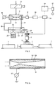
Dabei zeigen:
- Fig. 1
- schematisch eine Pulverbeschichtungs-Einrichtung, aufweisend ein Luftteilerorgan gemäss der DE-44 09 493 sowie einen Messensor und einen Regelkreis für das Gewährleisten einer konstanten Schichtdicke,
- Fig. 2
- schematisch dargestellt, eine Messeinrichtung sowie eine damit verbundene Hubeinrichtung für das Beschichten von Objekten mit unterschiedlicher Höhenausdehnung,
- Fig. 3
- schematisch dargestellt, eine Beschichtungseinrichtung, bei welcher die Aufladung des Pulvers durch Reibung erfolgt und in welcher Einrichtung die Beeinflussung der Schichtdicke durch Messen der Ladung des zu applizierenden Pulvers erfolgt und
- Fig. 3a
- die Aufladung bzw. den Sensor aus Fig. 3, im Schnitt, in Vergrösserung.
- Fig. 1
- schematically a powder coating device, having an air divider according to DE-44 09 493 and a measuring sensor and a control circuit for ensuring a constant layer thickness,
- Fig. 2
- shown schematically, a measuring device and a lifting device connected thereto for coating objects with different heights,
- Fig. 3
- schematically shown, a coating device in which the powder is charged by friction and in which device the layer thickness is influenced by measuring the charge of the powder to be applied and
- Fig. 3a
- the charge or the sensor of Fig. 3, in section, in enlargement.
In Fig. 1 sind Objekte 1 auf einem Förderband 2 angeordnet,
welche zu beschichten sind oder bereits beschichtet sind. Die
Beschichtung erfolgt mittels eines Beschichtungsorganes, wie
beispielsweise einer Pulverpistole 3, mittels welcher das Pulver
5 auf dem Objekt appliziert wird. Die Speisung beispielsweise
der Pistole 3 erfolgt mittels einer Pulverbeschichtungs-Einrichtung,
beschrieben in der DE-44 09 493. Zum besseren Verständnis
sei an dieser Stelle kurz diese Beschichtungs-Einrichtung
beschrieben sowie deren Funktionsweise. Die
Luftspeisung erfolgt beispielsweise über einen Eingangsdruck-Regler
9, mittels welchem die zugespiesene Luft eingestellt
werden kann. Die Luft wird einem Luftteilerorgan 11 zugeführt,
in welchem ein Doppelventil 13 vorgesehen ist, welches mittels
beispielsweise einem Drehregler 17 einstellbar ist. Mittels der
Anzeige 15 kann abgelesen werden, wie die Aufteilung der vom
Eingangsdruck-Regler 9 zugeführte Luft in Förderluft 19 und Dosierluft
21 aufgeteilt wird. Mittels der Förderluft 19 wird in
einem Injektor 22 beispielsweise durch Anordnen einer venturirohrartigen
Zone 15 aus einem Pulvervorrat 25 Pulver angesogen
und einer zweiten venturirohrartigen Zone 27 zugeführt. In
letztere Zone wird ebenfalls die Dosierluft 21 zugeführt und
mit der Förderluft und dem Pulver vermischt. Anschliessend wird
das Pulver über die Verbindungsleitung der Beschichtungspistole
3 zugeführt.1,
Mittels der in der DE-44 09 493 beschriebenen Dosiereinrichtung wird nun sichergestellt, dass das Pulver auch bei unterschiedlich zu applizierender Pulvermenge immer bei gleichbleibender Fördergeschwindigkeit der Pistole zugeführt und auf das Objekt appliziert wird. Dies ist vorteilhaft für das Erzielen einer gleichmässigen und qualitativ hochstehenden Beschichtung.By means of the dosing device described in DE-44 09 493 it is now ensured that the powder is also different The amount of powder to be applied is always the same Conveying speed fed to the gun and to the object is applied. This is beneficial for achieving one uniform and high quality coating.
Gemäss dem Schema in Fig. 1 ist nun anschliessend an die Beschichtungszone
ein Messensor 31 angeordnet, mittels welchem
die Schichtdicke am bereits beschichteten Objekt 1 gemessen
bzw. ermittelt werden kann. Die gemessene Schichtdicke wird einer
Aufzeichnung 33 zugeführt, in welcher der gemessene Wert
mit einem Sollwert 35 verglichen wird, welcher mittels einer
Einstellung 37 eingestellt bzw. verändert werden kann. Aufgrund
der Abweichung des Istwertes vom Sollwert wird nun eine Steuerung
39 derart beeinflusst, dass der Drehregler 17 betätigt
wird. Dies selbstverständlich nur dann, wenn der Istwert vom
Sollwert abweicht. Ist die Schichtdicke zu klein, wird der
Drehregler derart in Gang gesetzt, dass die Förderluft 19 erhöht
wird und entsprechend mehr Pulver gefördert wird. Ist die
Schichtdicke zu gross, wird der Drehregler 17 derart betätigt,
dass das Doppelventil 13 in Richtung Förderluft 19 bewegt wird,
respektive mehr Dosierluft der venturirohrartigen Einrichtung
27 zugeführt wird und entsprechend weniger Pulver gefördert
wird.According to the diagram in FIG. 1, the coating zone is now connected
a
Aufgrund dieses Regelkreises kann nun sichergestellt werden, dass nach einigen beschichteten Objekten eine konstante Schichtdicke appliziert wird, und dass bei allfällig auftretenden Schwankungen von Einflüssen, wie beispielsweise Temperatur, Luftfeuchtigkeit, Zusammensetzung des Pulvers usw., die Schichtdicke jederzeit automatisch korrigiert wird.Based on this control loop, it can now be ensured that after some coated objects a constant Layer thickness is applied, and that with any occurring Fluctuations of influences, such as temperature, Humidity, composition of the powder, etc., the Layer thickness is automatically corrected at any time.
In Fig. 2 ist erneut schematisch dargestellt, wie bei Objekten
mit unterschiedlicher Ausdehnung in Richtung ihrer Höhe bzw. in
Längsrichtung die verbrauchte Pulvermenge beim Beschichten optimiert
werden kann. Wiederum werden Objekte 1, welche über
Aufhängevorrichtungen 43 mit einer Fördereinrichtung 41 verbunden
bzw. an dieser angehängt sind, beschichtet, wobei zunächst
vor einer Beschichtungseinrichtung mittels einer Messeinrichtung
45 deren Höhe bzw. Längsausdehnung detektiert bzw. ermittelt
wird. Das mittels der Messeinrichtung 45 gemessene Signal
47 wird über eine Steuereinrichtung an die Beschichtungsanordnung
weitergeleitet, welche beispielsweise auf einer mobilen
Einrichtung 51 angeordnet ist. Diese Beschichtungsanordnung umfasst
einerseits die Beschichtungspistole 3, welche andererseits
auf einer Hubeinrichtung 49 angeordnet ist, um in der Höhe
verstellbar betrieben zu werden. Durch das Messignal 47 wird
nun der Hubweg der Pulverpistole derart gesteuert, dass das detektierte
Objekt 1 in seiner ganzen Höhen- bzw. Längsausdehnung
besprüht wird, jedoch die Hubbewegung derart begrenzt ist, dass
die Pistole nicht über die Begrenzung des Objektes in Längs- bzw.
Höhenrichtung hinaus bewegt bzw. betrieben wird. Dadurch
wird sichergestellt, dass nicht unnötig Pulver versprüht wird,
welches nicht auf der Oberfläche des Objektes abgelagert wird.2 is again shown schematically, as for objects
with different expansion in the direction of their height or in
Longitudinal direction optimizes the amount of powder used during coating
can be. Again objects 1, which are about
Aufgrund praktischer Erfahrungen hat es sich gezeigt, dass am
oberen Ende eines Objektes mehr Pulver zu versprühen ist als am
unteren Ende, da ein Teil des zu applizierenden Pulvers nach
unten fällt und somit im unteren Bereich die Pulverdichte in
der Sprühwolke höher ist als am oberen Ende des Objektes. Entsprechend
wird erfindungsgemäss vorgeschlagen, dass das gemessene
Signal 47 ebenfalls dazu verwendet wird, das Luftteilerorgan
11 aus Fig. 1 anzusteuern und die Pulvermenge, welche mittels
der Pistole 3 appliziert wird, entsprechend zu steuern.
Die Steuerung erfolgt derart, dass im oberen Bereich des Objektes
1 mehr Pulver versprüht wird als im unteren Bereich, wobei
erfahrungsgemäss pro Höhenmeter in Richtung nach oben ca. 3 bis
6 % mehr Pulver zu applizieren ist als am unteren Ende, um eine
gleichmässige Schichtdicke beim Beschichten des Objektes zu erzielen.
So ist es beispielsweise notwendig, bei einem Objekt
mit einer Längsausdehnung von ca. 4m bzw. mit einer Höhenausdehnung
von 4 m am oberen Ende ca. 10 bis 20 % mehr Pulver zu
applizieren als am unteren Ende dieses Objektes. Selbstverständlich
lässt sich nicht für alle Objekte und für alle Zusammensetzungen
des Beschichtungspulvers ein genauer Wert angeben,
sondern die unterschiedlichen Pulvermengen im oberen und im unteren
Bereich sind mittels praktischer Erfahrung zu ermitteln.
Wiederum hat es sich gezeigt, dass es nicht vorteilhaft ist,
einfach die zu applizierende Pulvermenge entlang der Höhenbewegung
der Pulverpistole zu variieren, sondern, dass es wichtig
ist, dass die Fördergeschwindigkeit des zu applizierenden Pulvers
wenigstens nahezu gleichbleibend ist, was nur mittels eines
Luftteilorganes 11, dargestellt in Fig. 1 bzw. beschrieben
in der DE-44 09 493, erzielt werden kann.Based on practical experience, it has been shown that on
spraying more powder at the top of an object than at
lower end, since part of the powder to be applied after
the powder density in
the spray cloud is higher than at the top of the object. Corresponding
it is proposed according to the invention that the measured
Wiederum ein weiteres Beispiel ist im Schema von Fig. 3 dargestellt,
welches mit dem Schema dargestellt in Fig. 1 weitgehendst
identisch ist. Die Ausnahme besteht darin, dass in der
Anordnung gemäss Fig. 3 nicht primär die Schichtdicke an einem
bereits beschichteten Objekt gemessen bzw. ermittelt wird, sondern,
dass hier die Ladung des zu applizierenden Pulvers in einem
Sensor 51 gemessen bzw. detektiert wird. Erfahrungsgemäss
hat es sich gezeigt, dass bei gleichbleibender Ladung wenigstens
nahezu gleiche Schichten auf Objekten 1 erzielt werden
können, mehr oder weniger unabhängig von der Menge des applizierten
Pulvers. Beispielsweise die Verwendung von mehr neuem
Pulver oder mehr rezykliertem Pulver führt zu unterschiedlichen
Ladungen im zu applizierenden Pulver, so dass unterschiedliche
Beschichtungen erzielt werden. Dies insbesondere bei Verwendung
von sogenannten Tribo-Pistolen, wo die Aufladung des Pulvers
mittels Reibung erfolgt. Die Ladung beträgt in der Regel ca. 1
- 5 µA bzw. 1 - 2 Coulomb/g.
Fig. 3a zeigt nun im Längsschnitt und vergrössert die Ladungsstrecke
bzw. den Sensor 51, in welchem die Ladung bei der Verwendung
von sogenannten Tribo-Pistolen erzeugt bzw. detektiert
wird. Das Pulver, welches in Pfeilrichtung gefördert wird,
reibt sich an einer Teflonbeschichtung 55 und wird geladen. Das
die Teflonbeschichtung umgebende Metallrohr 53 ist über ein
Messglied 57 an Erde verbunden. Der gemessene bzw. fliessende
Strom ist ein Parameter für die Ladungsmenge im Pulver/Luftgemisch.Another example is shown in the diagram of FIG. 3,
which with the scheme shown in Fig. 1 largely
is identical. The exception is that in the
3 not primarily the layer thickness on one
already coated object is measured or determined, but,
that here the charge of the powder to be applied in one
Das im Sensor bzw. Detektor 51 resp. 57 gemessene Ladungssignal
wird wiederum mit einem Istwert verglichen, und je nach dem erfolgt
die Ansteuerung des Drehreglers 17 durch eine Schaltung
39.That in the sensor or
Selbstverständlich ist es möglich, die in den drei Schematas
dargestellten Detektoren zu kombinieren, so dass beispielsweise
nicht nur die Ladung im Pulver gemessen wird, sondern ebenfalls
die Schichtdicke an bereits beschichteten Objekten und die
Steuerung des Drehreglers 17 durch Kombination von zwei oder
mehreren detektierten Signalen erfolgt.Of course, it is possible that in the three schemes
to combine the detectors shown, for example
not only the charge in the powder is measured, but also
the layer thickness of objects already coated and the
Control of the
Bei den in den drei Schematas dargestellten Beschichtungen bzw.
Messystemen handelt es sich selbstverständlich nur um Beispiele,
um die vorliegende Erfindung näher zu erläutern. So ist es
selbstverständlich möglich, weitere Parameter im Bereich der
Beschichtung, vor oder nach der Beschichtung, an Objekten zu
messen und dazu zu verwenden, das Luftteilerorgan zu steuern,
um die zu applizierende Pulvermenge einzustellen. So ist es
beispielsweise auch möglich, mittels optischer Sensoren die
Dichte der Pulverwolke 5 zu messen und mittels dem detektierten
Signal den Drehregler am Luftteilerorgan anzusteuern. Auch können
Temperaturmessungen, Feuchtigkeitsmessungen, Spannungsschwankungen
etc. dazu verwendet werden, um die zu applizierende
Pulvermenge zu steuern. Auch ist es möglich, wie bereits
eingangs der Beschreibung angeführt, vorab für bestimmte zu beschichtende
Objekte die Beschichtungsparameter zu optimieren
und abzuspeichern. Mittels eines Detektors bzw. Sensors zu Beginn
der Beschichtungsstrasse werden die jeweils zu beschichtenden
Objekte detektiert, und am Luftteilerorgan erfolgt die
optimierte Einstellung mittels der vorab ermittelten, optimierten
Parameter. Natürlich ist es möglich, diese vorab optimierten
Werte während dem Beschichten weiter zu optimieren und zu
ajustieren, beispielsweise unter Verwendung einer der drei vorab
und in den Figuren 1 bis 3 dargestellten Ausführungsvarianten.With the coatings or
Measuring systems are of course only examples,
to explain the present invention in more detail. That's the way it is
of course possible, further parameters in the area of
Coating, before or after coating, on objects
measure and use to control the air divider,
to adjust the amount of powder to be applied. That's the way it is
for example also possible by means of optical sensors
To measure the density of the
Erfindungswesentlich ist, dass das gemessene Signal nicht lediglich dazu verwendet wird, unabhängig von der gewählten Fördergeschwindigkeit des Pulvers beim Applizieren die Pulvermenge zu variieren, sondern, dass die Variation der Pulvermenge bei wenigstens nahezu gleichbleibender Fördergeschwindigkeit des Pulvers erfolgt, was beispielsweise mittels einer Beschichtungseinrichtung, beschrieben in der DE-44 09 493, ermöglicht wird.It is essential to the invention that the measured signal is not merely is used regardless of the selected conveyor speed of the powder when applying the amount of powder to vary, but that the variation in the amount of powder at least almost constant conveying speed of the Powder takes place, which for example by means of a coating device, described in DE-44 09 493, enables becomes.
Claims (11)
Applications Claiming Priority (2)
| Application Number | Priority Date | Filing Date | Title |
|---|---|---|---|
| CH66298 | 1998-03-19 | ||
| CH66298 | 1998-03-19 |
Publications (2)
| Publication Number | Publication Date |
|---|---|
| EP0943372A2 true EP0943372A2 (en) | 1999-09-22 |
| EP0943372A3 EP0943372A3 (en) | 2002-05-15 |
Family
ID=4192219
Family Applications (1)
| Application Number | Title | Priority Date | Filing Date |
|---|---|---|---|
| EP99105303A Withdrawn EP0943372A3 (en) | 1998-03-19 | 1999-03-15 | Controlled powder flow rate regulator |
Country Status (1)
| Country | Link |
|---|---|
| EP (1) | EP0943372A3 (en) |
Cited By (9)
| Publication number | Priority date | Publication date | Assignee | Title |
|---|---|---|---|---|
| EP1124088A1 (en) * | 2000-02-11 | 2001-08-16 | Cryospace l'air liquide aerospatiale | Process for thermal insulation of a metallic structure for cryogenic use |
| CN102188858A (en) * | 2010-03-18 | 2011-09-21 | 日本碍子株式会社 | Honeycomb filter production apparatus |
| CN102989611A (en) * | 2012-10-18 | 2013-03-27 | 吴江市元通纺织品有限公司 | Uniform coating machine |
| US8534221B2 (en) | 2010-03-18 | 2013-09-17 | Ngk Insulators, Ltd. | Honeycomb filter production apparatus |
| WO2015166374A1 (en) * | 2014-04-28 | 2015-11-05 | Marangoni S.P.A. | Distribution unit for a particulate material |
| US10071482B2 (en) * | 2015-08-19 | 2018-09-11 | Ford Global Technologies, Llc | Robotic vehicle painting instrument including a terahertz radiation device |
| US10323932B1 (en) | 2017-12-28 | 2019-06-18 | Ford Motor Company | System for inspecting vehicle bodies |
| EP3439792B1 (en) * | 2016-04-05 | 2022-10-05 | Sat (Surface Aluminium Technologies) S.R.L. In Short "Sat S.R.L." | System and process for coating profiles |
| EP4190454A1 (en) * | 2021-12-06 | 2023-06-07 | coatingAI AG | Coating production line system |
Citations (1)
| Publication number | Priority date | Publication date | Assignee | Title |
|---|---|---|---|---|
| DE4409493A1 (en) | 1993-03-26 | 1994-09-29 | Peter Ribnitz | Air-distributing valve |
Family Cites Families (4)
| Publication number | Priority date | Publication date | Assignee | Title |
|---|---|---|---|---|
| US3594211A (en) * | 1966-10-20 | 1971-07-20 | Ransburg Electro Coating Corp | Automatic coating system |
| DE4443859A1 (en) * | 1994-12-09 | 1996-06-13 | Friedrich Lothar | Measuring amount of lacquer powder flowing in electrostatic powder coating |
| DE19548607A1 (en) * | 1995-12-23 | 1997-06-26 | Gema Volstatic Ag | Powder spray coater |
| DE19623121C2 (en) * | 1996-06-10 | 2000-05-11 | Wagner International Ag Altsta | Method and device for photothermal testing of workpiece surfaces |
-
1999
- 1999-03-15 EP EP99105303A patent/EP0943372A3/en not_active Withdrawn
Patent Citations (1)
| Publication number | Priority date | Publication date | Assignee | Title |
|---|---|---|---|---|
| DE4409493A1 (en) | 1993-03-26 | 1994-09-29 | Peter Ribnitz | Air-distributing valve |
Cited By (16)
| Publication number | Priority date | Publication date | Assignee | Title |
|---|---|---|---|---|
| FR2805023A1 (en) * | 2000-02-11 | 2001-08-17 | Cryospace L Air Liquide Aerosp | PROCESS FOR THERMAL INSULATION OF A METAL STRUCTURE FOR CRYOGENIC USE |
| EP1124088A1 (en) * | 2000-02-11 | 2001-08-16 | Cryospace l'air liquide aerospatiale | Process for thermal insulation of a metallic structure for cryogenic use |
| CN102188858B (en) * | 2010-03-18 | 2014-11-05 | 日本碍子株式会社 | Honeycomb filter production apparatus |
| CN102188858A (en) * | 2010-03-18 | 2011-09-21 | 日本碍子株式会社 | Honeycomb filter production apparatus |
| EP2371452A1 (en) * | 2010-03-18 | 2011-10-05 | NGK Insulators, Ltd. | Honeycomb filter production apparatus |
| US8495968B2 (en) | 2010-03-18 | 2013-07-30 | Ngk Insulators, Ltd. | Honeycomb filter production apparatus |
| US8534221B2 (en) | 2010-03-18 | 2013-09-17 | Ngk Insulators, Ltd. | Honeycomb filter production apparatus |
| US8632852B2 (en) | 2010-03-18 | 2014-01-21 | Ngk Insulators, Ltd. | Method for producing a honeycomb filter |
| CN102989611A (en) * | 2012-10-18 | 2013-03-27 | 吴江市元通纺织品有限公司 | Uniform coating machine |
| WO2015166374A1 (en) * | 2014-04-28 | 2015-11-05 | Marangoni S.P.A. | Distribution unit for a particulate material |
| US20170050397A1 (en) * | 2014-04-28 | 2017-02-23 | Marangoni S.P.A. | Distribution Unit for a Particulate Material |
| US9873235B2 (en) * | 2014-04-28 | 2018-01-23 | Marangoni S.P.A. | Distribution unit for a particulate material |
| US10071482B2 (en) * | 2015-08-19 | 2018-09-11 | Ford Global Technologies, Llc | Robotic vehicle painting instrument including a terahertz radiation device |
| EP3439792B1 (en) * | 2016-04-05 | 2022-10-05 | Sat (Surface Aluminium Technologies) S.R.L. In Short "Sat S.R.L." | System and process for coating profiles |
| US10323932B1 (en) | 2017-12-28 | 2019-06-18 | Ford Motor Company | System for inspecting vehicle bodies |
| EP4190454A1 (en) * | 2021-12-06 | 2023-06-07 | coatingAI AG | Coating production line system |
Also Published As
| Publication number | Publication date |
|---|---|
| EP0943372A3 (en) | 2002-05-15 |
Similar Documents
| Publication | Publication Date | Title |
|---|---|---|
| EP0576498B2 (en) | Method and device for applying a paste | |
| EP3185680B1 (en) | Agricultural sprayer comprising a system for the automatic control of spraying profiles | |
| DE69021136T2 (en) | Device for regulating the flow of material in a process with delivery of a flowable medium. | |
| EP1445031A2 (en) | Device for applying adhesive to a workpiece | |
| DE102014225516B3 (en) | Method and device for coating a metal strip | |
| DE69429163T2 (en) | METHOD AND DEVICE FOR COATING THREE-DIMENSIONAL ARTICLES | |
| DE2224833C3 (en) | Device for measuring the gap of a pair of work rolls for a roll stand | |
| DE102014005077A1 (en) | Self-propelled construction machine and method for controlling a self-propelled construction machine | |
| DE19803240A1 (en) | Paint curtain applicator | |
| DE3434904C1 (en) | Method and system for monitoring the dimensions of a continuously extruded profile strip made of rubber or thermoplastic material consisting of one or more mixtures | |
| DE102019203394A1 (en) | Method for setting a parameter of an agricultural spraying device | |
| DE102014100829A1 (en) | Method for the controlled and / or regulated application of pesticides and agricultural distribution machine for the application of the method | |
| EP0690932A1 (en) | Blow-off device | |
| DE3135721C3 (en) | METHOD AND SYSTEM FOR SPRAYING COLORS | |
| DE3824908A1 (en) | METHOD AND DEVICE FOR ELECTROSTATIC SPRAY COATING | |
| DE19854675A1 (en) | Hot rolled metal strip cooling line, especially for wide strip, has individually regulated coolant delivery nozzles distributed across the strip width | |
| DE3309210A1 (en) | METHOD AND DEVICE FOR PNEUMATICALLY CONVEYING FINE GOODS | |
| EP0102937B1 (en) | Gauge control system of a cold rolling mill | |
| DE9112257U1 (en) | Cone warping machine | |
| DE10111383B4 (en) | Process for conveying coating powder to a coating unit and associated powder conveying device | |
| DE112005000426T5 (en) | A method of painting a paper / board web with a curtain coater | |
| DE4300868C1 (en) | Coating device | |
| DE3047857A1 (en) | FILTER STRAND PRODUCTION | |
| EP1298504B1 (en) | Method and device for improving the response characteristic of a command controlled installation | |
| DE69101977T2 (en) | Device for spreading a granular material. |
Legal Events
| Date | Code | Title | Description |
|---|---|---|---|
| PUAI | Public reference made under article 153(3) epc to a published international application that has entered the european phase |
Free format text: ORIGINAL CODE: 0009012 |
|
| AK | Designated contracting states |
Kind code of ref document: A2 Designated state(s): AT BE CH CY DE DK ES FI FR GB GR IE IT LI LU MC NL PT SE |
|
| AX | Request for extension of the european patent |
Free format text: AL;LT;LV;MK;RO;SI |
|
| PUAL | Search report despatched |
Free format text: ORIGINAL CODE: 0009013 |
|
| AK | Designated contracting states |
Kind code of ref document: A3 Designated state(s): AT BE CH CY DE DK ES FI FR GB GR IE IT LI LU MC NL PT SE |
|
| AX | Request for extension of the european patent |
Free format text: AL;LT;LV;MK;RO;SI |
|
| AKX | Designation fees paid | ||
| STAA | Information on the status of an ep patent application or granted ep patent |
Free format text: STATUS: THE APPLICATION IS DEEMED TO BE WITHDRAWN |
|
| 18D | Application deemed to be withdrawn |
Effective date: 20021001 |