EP0943379B1 - Verfahren und Vorrrichtung zum automatischen Biegen von profilierten Metallelementen oder dergleichen - Google Patents
Verfahren und Vorrrichtung zum automatischen Biegen von profilierten Metallelementen oder dergleichen Download PDFInfo
- Publication number
- EP0943379B1 EP0943379B1 EP99104039A EP99104039A EP0943379B1 EP 0943379 B1 EP0943379 B1 EP 0943379B1 EP 99104039 A EP99104039 A EP 99104039A EP 99104039 A EP99104039 A EP 99104039A EP 0943379 B1 EP0943379 B1 EP 0943379B1
- Authority
- EP
- European Patent Office
- Prior art keywords
- bending
- profiled elements
- bending position
- elements
- feed line
- Prior art date
- Legal status (The legal status is an assumption and is not a legal conclusion. Google has not performed a legal analysis and makes no representation as to the accuracy of the status listed.)
- Expired - Lifetime
Links
- 238000005452 bending Methods 0.000 title claims abstract description 111
- 238000000034 method Methods 0.000 title claims abstract description 18
- 239000002184 metal Substances 0.000 title claims abstract description 13
- 229910052751 metal Inorganic materials 0.000 title claims abstract description 13
- XEEYBQQBJWHFJM-UHFFFAOYSA-N Iron Chemical compound [Fe] XEEYBQQBJWHFJM-UHFFFAOYSA-N 0.000 claims abstract description 18
- 229910052742 iron Inorganic materials 0.000 claims abstract description 9
- 239000011150 reinforced concrete Substances 0.000 claims abstract description 6
- 238000004519 manufacturing process Methods 0.000 description 3
- 239000002994 raw material Substances 0.000 description 3
- 238000005520 cutting process Methods 0.000 description 2
- 230000000670 limiting effect Effects 0.000 description 2
- 230000002457 bidirectional effect Effects 0.000 description 1
- 230000015572 biosynthetic process Effects 0.000 description 1
- 238000003754 machining Methods 0.000 description 1
- 239000000463 material Substances 0.000 description 1
- 238000007493 shaping process Methods 0.000 description 1
Images


Classifications
-
- B—PERFORMING OPERATIONS; TRANSPORTING
- B21—MECHANICAL METAL-WORKING WITHOUT ESSENTIALLY REMOVING MATERIAL; PUNCHING METAL
- B21D—WORKING OR PROCESSING OF SHEET METAL OR METAL TUBES, RODS OR PROFILES WITHOUT ESSENTIALLY REMOVING MATERIAL; PUNCHING METAL
- B21D11/00—Bending not restricted to forms of material mentioned in only one of groups B21D5/00, B21D7/00, B21D9/00; Bending not provided for in groups B21D5/00 - B21D9/00; Twisting
- B21D11/10—Bending specially adapted to produce specific articles, e.g. leaf springs
- B21D11/12—Bending specially adapted to produce specific articles, e.g. leaf springs the articles being reinforcements for concrete
Definitions
- the present invention relates to a method for automatically bending metal profiled elements, particularly iron rods for reinforced concrete and the like, and to a machine which allows to perform the method automatically or semiautomatically.
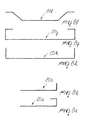
- stirrup bending machines which allow to produce stirrups and the like in different shapes, such as those shown for example in Figures 8a, 8b and 8c and designated by the reference numerals 20a, 20b and 20c for the sake of clarity.
- These machines have, in addition to suitable elements for straightening the iron rods, a feeder unit, suitable bending elements, and a cropping unit. Said units can be combined into a single machine or, as an alternative, their functions can be mutually integrated or separated and assigned to separate auxiliary units.
- the bending elements usually have a bending head, for example of the type shown in Figure 7; said bending head has a central pivot or spindle 13 and a bending pivot 14 which is supported eccentrically by a bending arm 15 which can rotate with respect to the axis of said central pivot 13.
- the bending head In order to perform bendings on opposite sides with respect to the axis of the iron rods to be bent, the bending head must be of the so-called bidirectional type, i.e., it must be able to perform the working movement in mutually opposite directions. This means that the positions of the central pivot and of the bending pivot must be reversed with respect to the axis of the iron rods to be bent.
- the machine In order to move said bending elements, the machine is capable of producing the vertical translatory motion of the bending head and a movement at right angles to the working surface, so as to allow said bending head to retract and then protrude again after moving past the rods to be bent.
- This vertical translatory motion is in any case still limited to the sum of the diameters of the rod and of the pivot 13.
- the above-cited machines have the characteristic that they support and handle the metal profiled elements being bent while leaving them attached to the raw material during the treatment.
- the machines In order to support the weight of the resulting item, avoiding permanent deformations due to the weight thereof, the machines often have a channel which acts as a support for the advancing items, so as to allow to produce straight bars and shaped elements having considerable dimensions, i.e., heavier than allowed by the rigidity of the raw material.
- the channel has a bottom which can be opened to discharge the item at the end of the process.
- Said channel is capable of receiving, in addition to the bars, most stirrups that have bends only in their front part, and is accordingly produced with a height which allows to accommodate commonly manufactured shaped items.
- the channel is open upward in an initial portion, so that the item is capable of protruding from said channel during production.
- stirrup bending machines allow to produce most of the items required in the field being considered, which are generally constituted by bars which have one or more bends at a single end, of the type shown in Figures 8d and 8e, in which said bent bars are designated by the reference numerals 20d and 20e respectively.
- said bending machines in addition to being provided with the elements suitable for bending the profiled elements in the rear part, require the presence of elements which allow the longitudinal movement of the item being treated after it has been cropped off the raw material. Moreover, during the longitudinal backward movement it is necessary to move beyond the obstacle constituted by the space occupied by the mechanical elements located in front of the bending elements, which inherently protrude from the working surface. This entails a further increase in the structural and operating complexity of the machine and in the associated costs in order to allow machining operations which are, in quantitative terms, a substantially small part of normal production.
- EP- 0 865 842 which is a document under Article 54(3) EPC, discloses a method and machine for automatically bending profiled elements.
- EP-0538 595 discloses a bending-shaping machine having multiple working levels, as defined in the preamble of claims 1 and 6.
- the aim of the present invention is to solve the above-described problem, by providing a method which allows to perform, very cheaply and simply, the automatic or semiautomatic bending of metal profiled elements having various shapes, particularly very long profiled elements provided with bends at both ends.
- an object of the present invention is to perform the above method by means of a machine, particularly of the stirrup bending type, whose structure is simple in concept, safely reliable in operation and versatile in use.
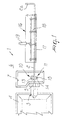
- the reference numeral 1 generally designates the machine for bending metal profiled elements 2, for example iron rods for reinforced concrete and the like, hereinafter termed rods for the sake of simplicity.
- the machine 1 has a line 3 for feeding the rods 2 to be bent.
- the rods 2 are fed by conventional elements, not shown, which are arranged in an initial region of the machine, the housing 4 of which is partially shown.
- a cropping unit 5 At the outlet of said feeder elements, along the feed line 3, there is a cropping unit 5 which is also of a known type.
- the machine is provided with bending means which are suitable to bend the ends of the rods 2.
- Said bending means are constituted by a bending unit 10, which can move between a first bending position 11 (Figure 1), at the bending line 3, and a second bending position 12 (Figure 2), which lies above said lower position for feeding the rods 2.
- the bending unit 10 is substantially constituted, in a per se known manner, by a cylindrical head which can be actuated so as to rotate and is provided with a central pivot 13 and with a bending pivot 14 which is supported eccentrically by a bending arm 15 which can rotate rigidly with respect to said head about the axis of said central pivot 13.
- the bending unit 10 acts at a working surface formed by a front bed 6; said bed 6 has an opening 7 from which the head of the bending unit 10 protrudes.
- the opening 7 is preferably formed at a recessed region of the bed 6 which has suitably inclined side walls.
- the machine At the lower position, along the feed line 3, the machine has a channel 16 which is suitable to receive, during an operating step, the portion of the rods 2 that protrudes in front of the bending means 10.
- the channel 16 has a bottom 17 which can be opened by means of a lever system 18 which is actuated by an actuator 19.
- the rod is then cropped to the chosen size by means of the cutting unit 5.
- the bending means 10 are prepared in the correct position for performing the bends in the rear part, i.e., so that the central pivot 13 lies above the rod 2 and the bending pivot 14 lies below it ( Figure 1 again).
- the bending means 10 move at right angles to the working surface 6, so as to retract with respect to said surface 6, and then protrude again after moving beyond the rod to be bent.
- the arm 15 is rotated from the front side, indicated by the arc A in Figure 7 and in which the front part 2a of the rod is bent, to the rear side, indicated by the arc P and in which the rear part 2b of the rod is bent.
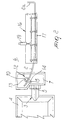
- the bending unit 10 is then moved into the upper position 12, raising the rear part of the rod ( Figure 2).
- the rear part of the rod is inclined and curved due to its elasticity and to its own weight, and therefore the electronic management devices with which the machine is equipped must provide for an automatic compensation of the bending angle, which can be optionally modified for this purpose by the intervention of the operator in order to achieve the intended final result.
- the rod 2 can be raised manually by the operator, who inserts it between the central pivot 13 and the bending pivot 14.
- the rod 2 is raised at the rear by a limited extent which is sufficient to clear the rod from the space occupied by the mechanical elements arranged to the rear of the bending means 10.
- the bending arm 15 perform an angular rotation, during the translatory stroke of the bending unit 10, from a vertical position to an inclined position which is substantially perpendicular to the tangent to the curve formed by the rod in the point of contact with the central pivot 13 (see Figure 2 again).
- the machine stops again to allow to operator to retract the rod again by the appropriate extent, subsequently resuming the cycle until the shape is completed.
- the illustrated solution allows to form the rear bends only in an upward direction, since the abutment for bending is constituted by the bottom 17 of the channel 16 which lies in front of the bending means 10, without the intervention of auxiliary elements. More specifically, the abutment action performed by said bottom 17 is provided by simple contact restraint reaction and therefore only in an upward direction.
- the operator manually inserts locators 26 in corresponding holes formed in the working surface 6, in front of the bending means 10, preferably close to said bending elements.
- locators 26 in corresponding holes formed in the working surface 6, in front of the bending means 10, preferably close to said bending elements.
- locator pins 26 it is of course possible for the locator pins 26 to be normally arranged inside the surface 6 and to protrude from it when necessary, the corresponding retraction and protrusion movements being determined by suitable actuators.
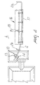
- Figure 5 illustrates another embodiment, in which the bottom of the channel 16, which has a conveniently elongated shape, is provided with a rear part 27 which is arranged adjacent to the bending means 10 and can be inclined at a suitable hinge 21; the inclination is performed by the operator directly after the lifting of the rod 2, through a suitable cam mechanism or automatically by means of an actuator 22.
- the rear upper lip of the channel 16 acts as a locator during bending.
- the elongation of the channel 16, or as an alternative the possibility to make it movable in a longitudinal direction so as to move toward the bending means as much as possible, arises from the need to minimize the distance between the central pivot 13 and the bottom 17 of said channel 16 during the bending of the rear part of the profiled elements, while said bottom 17 must be spaced or open when the machine forms bends in the front part of the profiled elements or when forming ordinary stirrups.
- the channel 16 has, on the bottom 17 and at the rear end arranged adjacent to the bending means 10, locator means 23 which are constituted for example by a shim element or eccentric element which is suitable to be interposed automatically or manually in order to re-establish the contact between the rod 2 and the bottom of said channel 16, which is no longer provided due to the upward motion of the rod 2, after the translatory motion of the rear part of said rod 2 into the second upper bending position (reference should be made to the enlarged-scale view of the detail R of Figure 6, where the dashed line 23a designates the deactivated position of said locator means 23).
- locator means 23 which are constituted for example by a shim element or eccentric element which is suitable to be interposed automatically or manually in order to re-establish the contact between the rod 2 and the bottom of said channel 16, which is no longer provided due to the upward motion of the rod 2, after the translatory motion of the rear part of said rod 2 into the second upper bending position (reference should be made to the enlarged-scale view of the
- the channel 16, or only its bottom 17, preferably have a considerable extension, so as to be as close as possible to the pivot 13 of the bending means 10, so that it can act as a locator with a minimal inclination of the rod in the rear part, particularly if a compact cutting element 5 is used.
- the method and the machine according to the invention allow to perform very simply and at low cost the automatic or semiautomatic bending of metal profiled elements in different shapes, particularly profiled elements of considerable length and provided with bends at both ends, such as for example those shown in Figures 8f, 8g and 8h.
- the bends formed in the rear part of the profiled elements have a precision which, despite being slightly lower than the precision of the front bends owing to the curvature applied to the rear part of the rods being bent, is fully within the tolerance range normally accepted in the field.
- the materials employed, as well as the shapes and the dimensions, may be any according to requirements.
Landscapes
- Engineering & Computer Science (AREA)
- Mechanical Engineering (AREA)
- Bending Of Plates, Rods, And Pipes (AREA)
Claims (9)
- Verfahren zum automatischen Biegen von profilierten Metallelementen, insbesondere Eisenstangen für Stahlbeton, mit folgenden Verfahrensschritten:die abzuschneidenden profilierten Elemente (2) entlang einer Zufuhrstrecke (3) zuzuführen, um ein vorderes Ende (2a) der profilierten Elemente in einer entlang der Zufuhrstrecke (3) angeordneten ersten Biegestellung in einer Biegeebene zu biegen,den Vorschub der profilierten Elemente (2) zu betätigen, um ihren vorderen Teil, der in Bezug auf die erste Biegestellung vorsteht, auf einem Führungskanal (6) ruhen zu lassen,die profilierten Elemente (2) auf eine Länge zuzuschneiden, die auch den zu biegenden hinteren Teil umfasst,den hinteren Teil der zugeschnittenen profilierten Elemente in eine zweite Biegestellung (12) zu verschieben,die gemessene Längsbewegung der profilierten Elemente durchzuführen, und dadurch gekennzeichnet, dass ein hinteres Ende (2b) der profilierten Elemente in der zweiten Biegestellung in der Biegeebene gebogen wird, und dadurch, dass die ersten und zweiten Biegestellungen in der Biegeebene angeordnet sind, die mit der Ebene zusammenfällt, in der die Zufuhrstrecke (3) angeordnet ist, und dadurch, dass, wenn die Ebene, die die Zufuhrstrecke enthält, eine im wesentlichen vertikale Ebene ist, die zweite Biegestellung um ein begrenztes Maß über der Zufuhrstrecke (3) liegt, das ausreicht, um an dem Raum vorbei zu bewegen, der von den mechanischen Elementen eingenommen wird, die hinter der ersten Biegestellung angeordnet sind.
- Verfahren nach Anspruch 1, dadurch gekennzeichnet, dass es weiterhin den Verfahrensschritt umfasst, die Translationsbewegung des hinteren Teils der profilierten Elemente (2) in der zweiten oberen Biegestellung entweder manuell oder mit Hilfe von Biegemitteln (10) zu erzeugen, die sich zwischen der ersten Biegestellung, die entlang der Zufuhrstrecke (3) angeordnet ist, und der oberen Biegestellung (12) bewegen.
- Verfahren nach Anspruch 1, dadurch gekennzeichnet, dass es weiterhin die Verfahrensschritte umfasst, Lokalisierungsmittel (26) auf einer Arbeitsfläche (6), die die Zufuhrstrecke (3) der profilierten Elemente (2) enthält, vor der ersten Biegestellung einzufügen und die gemessene Längsbewegung der profilierten Elemente manuell zu erzeugen, um die profilierten Elemente zwischen den Lokalisierungsmitteln (26) einzufügen.
- Verfahren nach Anspruch 1, dadurch gekennzeichnet, dass der Verfahrensschritt, die Translationsbewegung des hinteren Teils der profilierten Elemente (2) in der zweiten oberen Biegestellung (12) zu erzeugen, unter Winkeldrehung eines hinteren Teils des Führungskanals (16) durchgeführt wird, der schräg gestellt werden kann.
- Verfahren nach Anspruch 1, dadurch gekennzeichnet, dass es weiterhin den Verfahrensschritt umfasst, dem Führungskanal (16) Lokalisierungsmittel (23) beizuordnen, die geeignet sind, den Kontakt zwischen den profilierten Elementen und dem Boden des Führungskanals nach der Translationsbewegung des hinteren Teils der profilierten Elemente in die zweite obere Biegestellung wiederherzustellen.
- Maschine zum automatischen Biegen von profilierten Metallelementen, insbesondere Eisenstangen für Stahlbeton, die Folgendes aufweist: eine Strecke (3) zum Zuführen der zu biegenden profilierten Elemente (2), Biegemittel (10), die geeignet sind, die Enden der profilierten Elemente (2) zu biegen, einen Führungskanal (16), der geeignet ist, den in Bezug auf die erste Biegestellung nach vorne vorstehenden Teil der profilierten Elemente aufzunehmen, so dass er darauf ruht, und während des Biegens des hinteren Endes der profilierten Elemente als Lokalisierer wirkt, dadurch gekennzeichnet, dass die Biegemittel (10) geeignet sind, sich zwischen einer ersten Biegestellung, die entlang der Zufuhrstrecke (3) angeordnet ist, um ein vorderes Ende der profilierten Elemente in einer Biegeebene zu biegen, und einer zweiten Biegestellung, um ein hinteres Ende der profilierten Elemente in der Biegeebene zu biegen, zu bewegen, und dadurch, dass die ersten und zweiten oberen Biegestellungen in der im wesentlichen vertikalen Biegeebene angeordnet sind, die mit der Ebene zusammenfällt, in der die Zufuhrstrecke (3) angeordnet ist, und dadurch, dass die zweite Biegestellung über der Zufuhrstrecke angeordnet ist, wobei die zweite obere Biegestellung um ein begrenztes Maß beabstandet ist, das ausreicht, um an dem Raum vorbei zu bewegen, der von den mechanischen Elementen eingenommen wird, die hinter der ersten Biegestellung angeordnet sind.
- Maschine nach Anspruch 6, dadurch gekennzeichnet, dass sie Lokalisierungsmittel (26) aufweist, die geeignet sind, in entsprechende Löcher eingefügt zu werden, die vor den Biegemitteln (10), im wesentlichen nahe an den Biegemitteln (10), in der Arbeitsfläche (10) ausgebildet sind, und die profilierten Elemente (2) aufzunehmen, wenn sich der hintere Teil der profilierten Elemente in die zweite obere Biegestellung bewegt, um als oberer und unterer Lokalisierer für die profilierten Elemente zu wirken.
- Maschine nach Anspruch 6, dadurch gekennzeichnet, dass der Boden (17) des Führungskanals (16) mit einem hinteren Teil versehen ist, der angrenzend an die Biegemittel angeordnet ist und auf Grund von Betätigungsmitteln (22) an einem passenden Gelenk (21) schräg gestellt werden kann, um die profilierten Elemente zu stützen, wenn sich der hintere Teil der profilierten Elemente in die zweite obere Biegestellung bewegt.
- Maschine nach Anspruch 6, dadurch gekennzeichnet, dass dem Führungskanal (16) Anschlagmittel (17) beigeordnet sind, die geeignet sind, den Kontakt zwischen den profilierten Elementen und dem Boden des Führungskanals nach der Translationsbewegung des hinteren Teils der profilierten Elemente in die zweite obere Biegestellung wiederherzustellen.
Applications Claiming Priority (2)
| Application Number | Priority Date | Filing Date | Title |
|---|---|---|---|
| IT98BO000178A IT1299921B1 (it) | 1998-03-20 | 1998-03-20 | Procedimento per la piegatura automatica di profilati metallici e simili e macchina per attuare tale procedimento. |
| ITBO980178 | 1998-03-20 |
Publications (3)
| Publication Number | Publication Date |
|---|---|
| EP0943379A2 EP0943379A2 (de) | 1999-09-22 |
| EP0943379A3 EP0943379A3 (de) | 2000-05-17 |
| EP0943379B1 true EP0943379B1 (de) | 2003-06-18 |
Family
ID=11343049
Family Applications (1)
| Application Number | Title | Priority Date | Filing Date |
|---|---|---|---|
| EP99104039A Expired - Lifetime EP0943379B1 (de) | 1998-03-20 | 1999-03-16 | Verfahren und Vorrrichtung zum automatischen Biegen von profilierten Metallelementen oder dergleichen |
Country Status (4)
| Country | Link |
|---|---|
| EP (1) | EP0943379B1 (de) |
| AT (1) | ATE243079T1 (de) |
| DE (1) | DE69908841D1 (de) |
| IT (1) | IT1299921B1 (de) |
Families Citing this family (1)
| Publication number | Priority date | Publication date | Assignee | Title |
|---|---|---|---|---|
| ITBO20000603A1 (it) * | 2000-10-16 | 2002-04-16 | Schnell Spa | Metodo di lavoro in macchine per la piegatura automatica di profilatie simili e apparecchiatura per attuare tale metodo |
Citations (1)
| Publication number | Priority date | Publication date | Assignee | Title |
|---|---|---|---|---|
| ITMO970045A1 (it) * | 1997-03-20 | 1998-09-20 | Schnell S P A Schnell S P A | Procedimento e macchina per la piegatura automaticprocedimento e macchina per la piegatura automatica di profilati e sim ili. a di profilati e sim ili. |
Family Cites Families (1)
| Publication number | Priority date | Publication date | Assignee | Title |
|---|---|---|---|---|
| IT1252984B (it) * | 1991-10-21 | 1995-07-10 | Piegatrici Macch Elettr | Macchina piegatrice sagomatrice a livelli operativi multipli |
-
1998
- 1998-03-20 IT IT98BO000178A patent/IT1299921B1/it active IP Right Grant
-
1999
- 1999-03-16 EP EP99104039A patent/EP0943379B1/de not_active Expired - Lifetime
- 1999-03-16 AT AT99104039T patent/ATE243079T1/de not_active IP Right Cessation
- 1999-03-16 DE DE69908841T patent/DE69908841D1/de not_active Expired - Lifetime
Patent Citations (1)
| Publication number | Priority date | Publication date | Assignee | Title |
|---|---|---|---|---|
| ITMO970045A1 (it) * | 1997-03-20 | 1998-09-20 | Schnell S P A Schnell S P A | Procedimento e macchina per la piegatura automaticprocedimento e macchina per la piegatura automatica di profilati e sim ili. a di profilati e sim ili. |
Also Published As
| Publication number | Publication date |
|---|---|
| EP0943379A3 (de) | 2000-05-17 |
| IT1299921B1 (it) | 2000-04-04 |
| DE69908841D1 (de) | 2003-07-24 |
| ATE243079T1 (de) | 2003-07-15 |
| ITBO980178A0 (it) | 1998-03-20 |
| ITBO980178A1 (it) | 1999-09-20 |
| EP0943379A2 (de) | 1999-09-22 |
Similar Documents
| Publication | Publication Date | Title |
|---|---|---|
| US4996866A (en) | Orientable bending assembly | |
| US5025651A (en) | Movable shears upstream of a bending assembly and method to bend the trailing end of bars | |
| US4843859A (en) | Pipe bender | |
| US5193378A (en) | Device for bending rod-like material to form concrete reinforcements | |
| EP0379043B1 (de) | Stromabwärts einer Biegeeinrichtung angeordnete Ziehvorrichtung und Verfahren zum Biegen der hinteren Enden von Stangen | |
| JPH0455762B2 (de) | ||
| US5313814A (en) | Bending machine | |
| US6003358A (en) | Method and apparatus for forming bends in a selected sequence | |
| JPH08132164A (ja) | 金網折曲げ型及び金網折曲げ機 | |
| EP0865842B1 (de) | Verfahren und Vorrichtung zur automatischen Biegung von profilierten Elementen | |
| EP0943379B1 (de) | Verfahren und Vorrrichtung zum automatischen Biegen von profilierten Metallelementen oder dergleichen | |
| US5794481A (en) | Device for bending or curving hollow-section strips | |
| JPS6325849B2 (de) | ||
| US4886249A (en) | Spring bands for incorporation in spring units | |
| EP0850707B1 (de) | Biegeverfahren für Doppelbiegevorrichtung und dazugehörige Doppelbiegevorrichtung mit bewegbaren drehenden Teilen | |
| US4961335A (en) | Small-diameter metallic conduit | |
| JPH03180215A (ja) | 折曲げ加工機 | |
| US7204118B2 (en) | Hemming tool die assembly | |
| EP1199114B1 (de) | Verfahren zum automatischen Biegen von Profilstangen und dergleichen und Vorrichtung zur Durchführung des Verfahrens | |
| JPH0217695Y2 (de) | ||
| JP3068482U (ja) | 自動折曲げ装置 | |
| JP2795397B2 (ja) | ヘミング一体成形方法およびその装置 | |
| JP7245330B2 (ja) | プレスブレーキおよび二次元湾曲加工品の製造方法 | |
| JP4189947B2 (ja) | 成型用プレス | |
| SU1096017A1 (ru) | Станок дл гибки монтажных петель и анкеров |
Legal Events
| Date | Code | Title | Description |
|---|---|---|---|
| PUAI | Public reference made under article 153(3) epc to a published international application that has entered the european phase |
Free format text: ORIGINAL CODE: 0009012 |
|
| AK | Designated contracting states |
Kind code of ref document: A2 Designated state(s): AT DE DK ES FR IT NL |
|
| AX | Request for extension of the european patent |
Free format text: AL;LT;LV;MK;RO;SI |
|
| PUAL | Search report despatched |
Free format text: ORIGINAL CODE: 0009013 |
|
| AK | Designated contracting states |
Kind code of ref document: A3 Designated state(s): AT BE CH CY DE DK ES FI FR GB GR IE IT LI LU MC NL PT SE |
|
| AX | Request for extension of the european patent |
Free format text: AL;LT;LV;MK;RO;SI |
|
| 17P | Request for examination filed |
Effective date: 20001102 |
|
| AKX | Designation fees paid |
Free format text: AT DE DK ES FR IT NL |
|
| RIN1 | Information on inventor provided before grant (corrected) |
Inventor name: MONTEMARANI, MASSIMO |
|
| 17Q | First examination report despatched |
Effective date: 20010216 |
|
| GRAH | Despatch of communication of intention to grant a patent |
Free format text: ORIGINAL CODE: EPIDOS IGRA |
|
| GRAH | Despatch of communication of intention to grant a patent |
Free format text: ORIGINAL CODE: EPIDOS IGRA |
|
| GRAA | (expected) grant |
Free format text: ORIGINAL CODE: 0009210 |
|
| AK | Designated contracting states |
Designated state(s): AT DE DK ES FR IT NL |
|
| PG25 | Lapsed in a contracting state [announced via postgrant information from national office to epo] |
Ref country code: NL Free format text: LAPSE BECAUSE OF FAILURE TO SUBMIT A TRANSLATION OF THE DESCRIPTION OR TO PAY THE FEE WITHIN THE PRESCRIBED TIME-LIMIT Effective date: 20030618 Ref country code: FR Free format text: LAPSE BECAUSE OF FAILURE TO SUBMIT A TRANSLATION OF THE DESCRIPTION OR TO PAY THE FEE WITHIN THE PRESCRIBED TIME-LIMIT Effective date: 20030618 Ref country code: AT Free format text: LAPSE BECAUSE OF FAILURE TO SUBMIT A TRANSLATION OF THE DESCRIPTION OR TO PAY THE FEE WITHIN THE PRESCRIBED TIME-LIMIT Effective date: 20030618 |
|
| REF | Corresponds to: |
Ref document number: 69908841 Country of ref document: DE Date of ref document: 20030724 Kind code of ref document: P |
|
| PG25 | Lapsed in a contracting state [announced via postgrant information from national office to epo] |
Ref country code: DK Free format text: LAPSE BECAUSE OF FAILURE TO SUBMIT A TRANSLATION OF THE DESCRIPTION OR TO PAY THE FEE WITHIN THE PRESCRIBED TIME-LIMIT Effective date: 20030918 |
|
| PG25 | Lapsed in a contracting state [announced via postgrant information from national office to epo] |
Ref country code: DE Free format text: LAPSE BECAUSE OF FAILURE TO SUBMIT A TRANSLATION OF THE DESCRIPTION OR TO PAY THE FEE WITHIN THE PRESCRIBED TIME-LIMIT Effective date: 20030919 |
|
| PG25 | Lapsed in a contracting state [announced via postgrant information from national office to epo] |
Ref country code: ES Free format text: LAPSE BECAUSE OF FAILURE TO SUBMIT A TRANSLATION OF THE DESCRIPTION OR TO PAY THE FEE WITHIN THE PRESCRIBED TIME-LIMIT Effective date: 20030929 |
|
| NLV1 | Nl: lapsed or annulled due to failure to fulfill the requirements of art. 29p and 29m of the patents act | ||
| PLBE | No opposition filed within time limit |
Free format text: ORIGINAL CODE: 0009261 |
|
| STAA | Information on the status of an ep patent application or granted ep patent |
Free format text: STATUS: NO OPPOSITION FILED WITHIN TIME LIMIT |
|
| 26N | No opposition filed |
Effective date: 20040319 |
|
| EN | Fr: translation not filed | ||
| PGFP | Annual fee paid to national office [announced via postgrant information from national office to epo] |
Ref country code: IT Payment date: 20090326 Year of fee payment: 11 |
|
| PG25 | Lapsed in a contracting state [announced via postgrant information from national office to epo] |
Ref country code: IT Free format text: LAPSE BECAUSE OF NON-PAYMENT OF DUE FEES Effective date: 20100316 |