EP0943533B1 - Radaufhängungssystem für Raupenfahrzeuge - Google Patents
Radaufhängungssystem für Raupenfahrzeuge Download PDFInfo
- Publication number
- EP0943533B1 EP0943533B1 EP99850030A EP99850030A EP0943533B1 EP 0943533 B1 EP0943533 B1 EP 0943533B1 EP 99850030 A EP99850030 A EP 99850030A EP 99850030 A EP99850030 A EP 99850030A EP 0943533 B1 EP0943533 B1 EP 0943533B1
- Authority
- EP
- European Patent Office
- Prior art keywords
- suspension system
- tubular element
- torsion bar
- sleeve
- pendulum
- Prior art date
- Legal status (The legal status is an assumption and is not a legal conclusion. Google has not performed a legal analysis and makes no representation as to the accuracy of the status listed.)
- Expired - Lifetime
Links
Images
Classifications
-
- B—PERFORMING OPERATIONS; TRANSPORTING
- B60—VEHICLES IN GENERAL
- B60G—VEHICLE SUSPENSION ARRANGEMENTS
- B60G21/00—Interconnection systems for two or more resiliently-suspended wheels, e.g. for stabilising a vehicle body with respect to acceleration, deceleration or centrifugal forces
- B60G21/02—Interconnection systems for two or more resiliently-suspended wheels, e.g. for stabilising a vehicle body with respect to acceleration, deceleration or centrifugal forces permanently interconnected
- B60G21/04—Interconnection systems for two or more resiliently-suspended wheels, e.g. for stabilising a vehicle body with respect to acceleration, deceleration or centrifugal forces permanently interconnected mechanically
- B60G21/05—Interconnection systems for two or more resiliently-suspended wheels, e.g. for stabilising a vehicle body with respect to acceleration, deceleration or centrifugal forces permanently interconnected mechanically between wheels on the same axle but on different sides of the vehicle, i.e. the left and right wheel suspensions being interconnected
- B60G21/051—Trailing arm twist beam axles
-
- B—PERFORMING OPERATIONS; TRANSPORTING
- B62—LAND VEHICLES FOR TRAVELLING OTHERWISE THAN ON RAILS
- B62D—MOTOR VEHICLES; TRAILERS
- B62D55/00—Endless track vehicles
- B62D55/08—Endless track units; Parts thereof
- B62D55/104—Suspension devices for wheels, rollers, bogies or frames
- B62D55/108—Suspension devices for wheels, rollers, bogies or frames with mechanical springs, e.g. torsion bars
- B62D55/1083—Torsion-bar springs
Definitions
- the present invention relates to a suspension system for a tracked vehicle according to the preamble of claim 1, as known from DE-C-968975.
- the torsion bar alone takes up the entire suspension movement of the pendulum arms, which results in above all a limited possible angular capacity of the suspension system.
- a primary object of the present invention is to develop the abovementioned known suspension system in order to prevent overtwisting of the torsion bar in extreme cases.
- a suspension system with the features of claim 1; thus in particular complementary engagement members are arranged on the outside of the bearing sleeve of the pendulum arms and on the inside of the end portion surrounding this of the tubular element, which members are designed to allow a predetermined, limited free rotation movement of the bearing sleeve relative to the end portion of the tubular element and, in the event of this free relative rotation movement being exceeded, to be brought into engagement with one another, the pendulum arm short-circuiting the torque force directly to the rubber bushing.
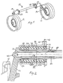
- 10 designates generally a wheel mounting for a pair of support wheels 12 for a tracked vehicle (not shown), the wheel mounting 10 comprising a suspension system according to the present invention.
- a tracked vehicle usually comprises a number of support wheel mountings 10 positioned one following another along the vehicle, the support wheels 12 on each side of the vehicle bearing against the inside of the lower strand of a respective endless drive track.
- Each wheel mounting 10 comprises a pendulum arm 14 for each support wheel 12, the latter being rotatably mounted at one (the outer) end of the pendulum arm 14. As shown in Fig.
- each pendulum arm 14 has an axially inwardly directed bearing sleeve 16 and is firmly connected, by means of a splined joint 17 and a screw joint 20, to a respective end of a first spring element in the form of a torsion bar 18.
- the torsion bar 18 therefore extends across the longitudinal extent of the vehicle and interconnects the pendulum arms 14.
- a central portion (not shown) of the torsion bar 18 is connected in a rotationally fixed manner via a splined joint to a torque-transmitting tubular element 22 which surrounds the torsion bar 18 and the end portions of which surround the bearing sleeves 16 of the pendulum arms 14.
- the bearing sleeves 16 are mounted on the inside of the tube ends via a pair of sliding bearings 24.
- a second torsion element in the form of a rubber bushing 26 is vulcanized firmly on the outside of each end portion of the tubular element 22.
- An outer bushing sleeve 28 is vulcanized firmly on the outside of the rubber bushing 26 and is supported in a support sleeve 30 with an anchoring flange 32 for fastening the entire wheel mounting 10 in the two opposite sides of the tracked vehicle.
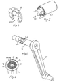
- the outer bushing sleeve 28 is provided with rotation-preventing engagement members in the form of teeth or tongues 34 on one end edge (Fig. 3), which are arranged so as to engage with recesses 36 in an anchoring ring 38 (Fig. 4) which is to be mounted firmly against the inside of a side wall 40 of the vehicle body (Fig.
- the anchoring ring 38 may be split or have a recess 42 (Fig. 4) so as to make possible slipping-on over the tubular element 22 before installation of the wheel mounting 10 in the vehicle.
- two torsion springs (the torsion bar 18 and the rubber bushing 26) are therefore coupled in series with one another, the torsion bar 18 and the rubber bushing 26 being designed so as each to take up roughly half the twisting that is caused by the pendulum arms 14 during normal deflection movements (upward deflection).
- engagement members are arranged - in a portion between the axially separate sliding bearings 24 - between the bearing sleeve 16 of the pendulum arm 14 and the respective end portion of the tubular element 22, which members are designed to allow a predetermined, limited free rotation movement of the bearing sleeve 16 relative to the end portion of the tubular element 22 and, in the event of this free relative rotation movement of the bearing sleeve 16 being exceeded, to be brought into engagement with one another so as thus to "short-circuit" the torque transmission from the pendulum arm 14 directly to the rubber bushing 26 which then takes up all the excess torque.
- these engagement members can take the form of a number of axial ribs 44 which are separate in the circumferential direction and formed between wide grooves 46 on the outside of the bearing sleeve 16 and of corresponding axial, inwardly projecting ribs 48 formed between wide grooves 50 on the inside of the end portions of the tubular element 22 (Fig. 6), the ribs 44 on the bearing sleeve 16 being capable of freely moving an angular distance corresponding to the distance between two opposite radial side surfaces of two adjacent ribs 48 on the tube ends before the ribs 44 come into contact with the ribs 48 and transmit the excess torque to the rubber bushing 26.
- the tubular element 22 therefore connects the two rubber bushings 26 on the left and the right side of the tracked vehicle.
- a corresponding blocking of the twisting of the torsion bar 18 can take place on one side, in which case it is possible for excess torque from one support wheel to be distributed to both rubber bushings 26 via the torque-transmitting tubular element 22, the characteristic torsion (1-2°) of which is negligible in this connection.
- the suspension system according to the invention provides a very great angular capacity at the same time as it makes possible symmetry of the track sets of the vehicle and very low transmission of bending moment to the side of the vehicle.
- the rubber bushings eliminate any minor errors of geometry and provide a certain degree of vibration insulation.
Landscapes
- Engineering & Computer Science (AREA)
- Mechanical Engineering (AREA)
- Chemical & Material Sciences (AREA)
- Combustion & Propulsion (AREA)
- Transportation (AREA)
- Vehicle Body Suspensions (AREA)
- Springs (AREA)
- Devices For Conveying Motion By Means Of Endless Flexible Members (AREA)
- Seal Device For Vehicle (AREA)
Claims (9)
- Aufhängungssystem für ein Raupenfahrzeug der Bauart, die Stützräder (12) aufweist, die entlang gegenüberliegender Seiten des Fahrzeuges zur Anlage gegen jeweils die Innenseite einer endlosen Antriebskette angeordnet sind, wobei die Stützräder (12) drehbar an einem äußeren Ende jeweils eines Pendelarmes (14) angebracht sind, der an seinem inneren Ende, in der Seite des Fahrzeugkörpers, begrenzt schwenkbar angebracht ist, und wobei die Pendelarme (14), für jedes Paar einander gegenüberliegender Stützräder (12) mittels eines ersten Aufhängungselementes (18) in Form eines Torsionsstabs miteinander verbunden sind, der sich quer zur Längserstreckung des Fahrzeuges und koaxial zu den Schwenkachsen der Pendelarme (14) erstreckt, wobei ein mittlerer Bereich des Torsionsstabs (18) mit einem diesen umgebenden, länglichen rohrförmigen Element (22) drehfest verbunden ist, dessen einer Endabschnitt eine mit einem Pendelarm (14) verbundene Lagerbuchse (16) koaxial umschließt und abstützt, dessen anderer Endabschnitt eine Lagerbuchse (16) koaxial umschließt und abstützt, die mit dem anderen, gegenüberliegenden Pendelarm (14) verbunden ist, wobei eine Gummibuchse auf der Außenseite jedes Endbereiches des rohrförmigen Elementes (22) montiert ist, und wobei das Torsionselement wiederum umgeben ist von und fest verbunden mit einer äußeren Buchsenhülse (28) ist, die ausgebildet ist, um in der Seite des Fahrzeugkörpers befestigt zu sein, dadurch gekennzeichnet, dass jede Gummihülse fest an dem rohrförmigen Element (22) angebracht ist um ein zweites Torsionselement (26) zu bilden und dadurch, dass zusätzliche Eingriffselemente (44, 48; 46, 50) an der Außenseite der Lagerbuchse (16) der Pendelarme (14) und an der Innenseite des, diesen umgebenden, Endabschnitts des rohrförmigen Elements (22), angeordnet sind, wobei diese Elemente ausgebildet sind, um eine vorbestimmte, begrenzte freie Drehbewegung der Lagerbuchse (16) relativ zum Endbereich des rohrförmigen Elements (22) zu erlauben und, die im Fall, dass diese freie Relativdrehbewegung überschritten wird, miteinander in Eingriff gebracht werden, um ein Überdrehen des Torsionsstabes (18) zu vermeiden.
- Aufhängungssystem nach Anspruch 1, dadurch gekennzeichnet, dass die Eingriffselemente an einem Teil axiale Nuten (46, 50) aufweisen, und am anderen Teil Rippen (44, 48), die in diese Nuten eingreifen, wobei die Rippen (44, 48) eine geringere Breite als die Nuten (46, 50) aufweisen.
- Aufhängungssystem nach Anspruch 1 oder 2, dadurch gekennzeichnet, dass der Torsionsstab (18) drehfest durch eine Keilwellenverbindung, mit dem mittleren Bereich des rohrförmigen Elements (22) verbunden ist.
- Aufhängungssystem nach einem der Ansprüche 1-3, dadurch gekennzeichnet, dass jede äußere Buchsenhülse (28) von einer Stützhülse (30) mit einem Befestigungsflansch (32) gestützt wird, um die gesamte Stützrad-Aufhängung (10) an, zugeordneten Verankerungen (38) in den Seiten des Fahrzeugaufbaus zu befestigen.
- Aufhängungssystem nach Anspruch 4, dadurch gekennzeichnet, dass jede äußere Buchsenhülse (28) mehrere axial ausgerichtete Zungen (34), für einen die Drehung verhindernden Verriegelungseingriff mit korrespondierenden Ausnehmungen (36) in der Verankerung (38), oder umgekehrt, aufweist.
- Aufhängungssystem nach einem der Ansprüche 1-5, dadurch gekennzeichnet, dass die Lagerbuchsen (16) der Pendelarme (14) in den Endbereichen des rohrförmigen Elements (22) durch Gleitlager (24) befestigt sind.
- Aufhängungssystem nach einem der Ansprüche 1-6, dadurch gekennzeichnet, dass die Gummibuchsen (26) fest auf die Endabschnitte des rohrförmigen Elements (22) und auf die äußeren Buchsenhülse (28) vulkanisiert sind.
- Aufhängungssystem nach einem der Ansprüche 1-7, dadurch gekennzeichnet, dass die Gummibuchsen (26) für jedes Stützradpaar, und der Torsionsstab (18) derart dimensioniert sind, so dass jede ungefähr die Hälfte der relevanten Verdrehung aufnimmt.
- Aufhängungssystem nach einem der Ansprüche 1-8, dadurch gekennzeichnet, dass die zwei Gummibuchsen (26) für jedes Stützradpaar ausgebildet sind, um an der entsprechenden Außenseite des Fahrzeugkörpers (40) angebracht zu werden.
Applications Claiming Priority (2)
| Application Number | Priority Date | Filing Date | Title |
|---|---|---|---|
| SE9800922 | 1998-03-19 | ||
| SE9800922A SE511665C2 (sv) | 1998-03-19 | 1998-03-19 | Fjädringssystem för bandfordon |
Publications (3)
| Publication Number | Publication Date |
|---|---|
| EP0943533A2 EP0943533A2 (de) | 1999-09-22 |
| EP0943533A3 EP0943533A3 (de) | 2001-01-24 |
| EP0943533B1 true EP0943533B1 (de) | 2005-10-05 |
Family
ID=20410616
Family Applications (1)
| Application Number | Title | Priority Date | Filing Date |
|---|---|---|---|
| EP99850030A Expired - Lifetime EP0943533B1 (de) | 1998-03-19 | 1999-03-03 | Radaufhängungssystem für Raupenfahrzeuge |
Country Status (5)
| Country | Link |
|---|---|
| EP (1) | EP0943533B1 (de) |
| AT (1) | ATE305875T1 (de) |
| DE (1) | DE69927542T2 (de) |
| NO (1) | NO315360B1 (de) |
| SE (1) | SE511665C2 (de) |
Families Citing this family (11)
| Publication number | Priority date | Publication date | Assignee | Title |
|---|---|---|---|---|
| FR2813813B1 (fr) * | 2000-09-12 | 2002-11-15 | Michelin & Cie | Procede de fixation d'au moins un insert de guidage entre deux tubes coaxiaux, notamment dans un dispositif anti-roulis de vehicule automobile |
| KR101382924B1 (ko) * | 2006-12-19 | 2014-04-10 | 두산인프라코어 주식회사 | 중장비의 무한궤도용 서스펜션 장치 |
| ITSA20080029A1 (it) * | 2008-09-18 | 2008-12-18 | Francesco Romanelli | Ammortizzatore a barra di torsione |
| SE536631C2 (sv) * | 2012-06-27 | 2014-04-15 | BAE Systems Hägglunds Aktiebolag | Fjädringssystem för bandfordon |
| SE537037C2 (sv) * | 2013-04-29 | 2014-12-16 | BAE Systems Hägglunds Aktiebolag | Fjädringssystem för bandfordon samt ett bandfordon med sådant fjädringssystem |
| US9505051B2 (en) * | 2014-07-09 | 2016-11-29 | The Boeing Company | Mobile platforms for performing operations along an exterior of a fuselage assembly |
| CN105416425B (zh) * | 2015-11-12 | 2017-12-12 | 建湖隆新石油机械有限公司 | 一种履带车辆负重轮用扭力杆减震机构 |
| CN110562340A (zh) * | 2019-08-15 | 2019-12-13 | 哈尔滨北方防务装备股份有限公司 | 一种履带车辆的品字结构扭杆弹簧 |
| CN110641566A (zh) * | 2019-11-06 | 2020-01-03 | 三一汽车制造有限公司 | 履带车悬挂组件和履带车 |
| CN112498507A (zh) * | 2020-11-28 | 2021-03-16 | 哈尔滨北方防务装备股份有限公司 | 一种双节履带车橡胶扭转花键z型轴减振装置 |
| CN112918501B (zh) * | 2021-03-26 | 2024-05-28 | 镇江昊翔机械有限公司 | 一种橡胶扭力半轴组件及其组装方法 |
Family Cites Families (11)
| Publication number | Priority date | Publication date | Assignee | Title |
|---|---|---|---|---|
| DE688421C (de) * | 1936-01-01 | 1940-02-20 | Continental Gummi Werke Akt Ge | Abfederung, insbesondere fuer Kraftfahrzeuge, mit mehreren hintereinandergeschalteten Federn verschiedener Staerke |
| US2270572A (en) * | 1938-11-02 | 1942-01-20 | Chrysler Corp | Wheel suspension for motor vehicles |
| GB532393A (en) * | 1939-07-21 | 1941-01-23 | Silentbloc | Improvements in or relating to flexible joints |
| GB554695A (en) * | 1942-01-13 | 1943-07-15 | Dunlop Rubber Co | Improvements in joints and bearings comprising resilient elements applicable to wheels suspension and other purposes |
| DE968975C (de) * | 1951-10-11 | 1958-04-10 | Ernst Hahn | Drehstabfederung fuer Zwillingsachsen von Fahrzeugen, insbesondere von Anhaengerfahrzeugen |
| DE928449C (de) * | 1953-06-21 | 1955-06-02 | Volkswagenwerk G M B H | Drehstabgefederte Achse fuer Kraftfahrzeuge |
| US3504931A (en) * | 1967-10-04 | 1970-04-07 | Us Army | Vehicle variable height actuator |
| US3724587A (en) * | 1971-04-05 | 1973-04-03 | Christiania Spigerverk | Suspension for pivotal track frames on terrain motor vehicles |
| FR2154297B1 (de) * | 1971-09-27 | 1975-02-21 | Citroen Sa | |
| FR2528365A1 (fr) * | 1982-06-15 | 1983-12-16 | Aerospatiale | Suspension a bras oscillants pour un train de deux roues d'un vehicule et systeme de rappel elastique et de couplage antiroulis pour une telle suspension |
| JPS60184735A (ja) * | 1984-02-29 | 1985-09-20 | Hino Motors Ltd | ト−シヨンバ− |
-
1998
- 1998-03-19 SE SE9800922A patent/SE511665C2/sv not_active IP Right Cessation
-
1999
- 1999-03-03 DE DE69927542T patent/DE69927542T2/de not_active Expired - Lifetime
- 1999-03-03 AT AT99850030T patent/ATE305875T1/de active
- 1999-03-03 EP EP99850030A patent/EP0943533B1/de not_active Expired - Lifetime
- 1999-03-18 NO NO19991311A patent/NO315360B1/no not_active IP Right Cessation
Also Published As
| Publication number | Publication date |
|---|---|
| SE9800922L (sv) | 1999-09-20 |
| EP0943533A2 (de) | 1999-09-22 |
| SE511665C2 (sv) | 1999-11-08 |
| DE69927542T2 (de) | 2006-07-13 |
| NO991311D0 (no) | 1999-03-18 |
| SE9800922D0 (sv) | 1998-03-19 |
| NO991311L (no) | 1999-09-20 |
| ATE305875T1 (de) | 2005-10-15 |
| DE69927542D1 (de) | 2006-02-16 |
| NO315360B1 (no) | 2003-08-25 |
| EP0943533A3 (de) | 2001-01-24 |
Similar Documents
| Publication | Publication Date | Title |
|---|---|---|
| EP0943533B1 (de) | Radaufhängungssystem für Raupenfahrzeuge | |
| US7909129B2 (en) | Steering shaft support structure of motor-driven steering assist apparatus | |
| US6306045B1 (en) | Assembly having a constant velocity fixed joint and a connecting shaft | |
| US4168086A (en) | Radius arm support for a driving axle | |
| US5484339A (en) | Articulated coupling | |
| US5566969A (en) | Rear axle suspension with reduced oversteer | |
| CA2260418A1 (en) | Plug in direct acting stabilizer bar link | |
| US6074016A (en) | Flexible axle embodying a crosspiece and trailing arms | |
| EP0770506B1 (de) | Verbesserungen in oder in Beziehung auf Antiroll-Stabanordnungen für Strassenfahrzeuge | |
| WO2006072012A2 (en) | Center bearing assembly | |
| EP0122891A1 (de) | Änderungen an Aufhängungen von Kraftfahrzeugen | |
| EP0162141A1 (de) | Kraftfahrzeuglenksäule mit biegungsbeständiger flexibler Schleifkupplung | |
| GB2302389A (en) | A resilient Cardan joint for steering columns | |
| EP0275655A1 (de) | Antriebswelle | |
| EP0213089B1 (de) | Elastisches Lager mit variabler Flexibilität, insbesondere für Kraftfahrzeugaufhängungen | |
| KR101720275B1 (ko) | 철도차량용 안티롤바 어셈블리 | |
| KR20220026688A (ko) | 듀얼 조인트 부시 | |
| KR101989913B1 (ko) | 자동차용 조향축 | |
| KR20180026197A (ko) | 액티브 롤 스태빌라이저 | |
| GB2158195A (en) | Torque transmission device | |
| JP2001041234A (ja) | ピローボールブッシュ | |
| KR100458219B1 (ko) | 유니버셜 조인트의 슬립장치 | |
| CA2293757A1 (en) | Compensating coupling | |
| KR20010019367A (ko) | 프로펠러 샤프트의 센터 베어링 장착구조 | |
| JPH0614096Y2 (ja) | すべりブッシング |
Legal Events
| Date | Code | Title | Description |
|---|---|---|---|
| PUAI | Public reference made under article 153(3) epc to a published international application that has entered the european phase |
Free format text: ORIGINAL CODE: 0009012 |
|
| AK | Designated contracting states |
Kind code of ref document: A2 Designated state(s): AT DE FI FR GB IT SE |
|
| AX | Request for extension of the european patent |
Free format text: AL;LT;LV;MK;RO;SI |
|
| PUAL | Search report despatched |
Free format text: ORIGINAL CODE: 0009013 |
|
| AK | Designated contracting states |
Kind code of ref document: A3 Designated state(s): AT BE CH CY DE DK ES FI FR GB GR IE IT LI LU MC NL PT SE |
|
| AX | Request for extension of the european patent |
Free format text: AL;LT;LV;MK;RO;SI |
|
| 17P | Request for examination filed |
Effective date: 20010709 |
|
| AKX | Designation fees paid |
Free format text: AT DE FI FR GB IT SE |
|
| GRAP | Despatch of communication of intention to grant a patent |
Free format text: ORIGINAL CODE: EPIDOSNIGR1 |
|
| GRAS | Grant fee paid |
Free format text: ORIGINAL CODE: EPIDOSNIGR3 |
|
| RAP1 | Party data changed (applicant data changed or rights of an application transferred) |
Owner name: ALVIS HAEGGLUNDS AB |
|
| 17Q | First examination report despatched |
Effective date: 20040625 |
|
| RAP1 | Party data changed (applicant data changed or rights of an application transferred) |
Owner name: LAND SYSTEMS HAEGGLUNDS AKTIEBOLAG |
|
| GRAA | (expected) grant |
Free format text: ORIGINAL CODE: 0009210 |
|
| AK | Designated contracting states |
Kind code of ref document: B1 Designated state(s): AT DE FI FR GB IT SE |
|
| REG | Reference to a national code |
Ref country code: GB Ref legal event code: FG4D |
|
| REG | Reference to a national code |
Ref country code: SE Ref legal event code: TRGR |
|
| REF | Corresponds to: |
Ref document number: 69927542 Country of ref document: DE Date of ref document: 20060216 Kind code of ref document: P |
|
| ET | Fr: translation filed | ||
| PLBE | No opposition filed within time limit |
Free format text: ORIGINAL CODE: 0009261 |
|
| STAA | Information on the status of an ep patent application or granted ep patent |
Free format text: STATUS: NO OPPOSITION FILED WITHIN TIME LIMIT |
|
| 26N | No opposition filed |
Effective date: 20060706 |
|
| REG | Reference to a national code |
Ref country code: FR Ref legal event code: PLFP Year of fee payment: 18 |
|
| PGFP | Annual fee paid to national office [announced via postgrant information from national office to epo] |
Ref country code: FR Payment date: 20160321 Year of fee payment: 18 Ref country code: AT Payment date: 20160322 Year of fee payment: 18 Ref country code: SE Payment date: 20160321 Year of fee payment: 18 Ref country code: GB Payment date: 20160321 Year of fee payment: 18 Ref country code: FI Payment date: 20160311 Year of fee payment: 18 |
|
| PGFP | Annual fee paid to national office [announced via postgrant information from national office to epo] |
Ref country code: DE Payment date: 20160330 Year of fee payment: 18 |
|
| PGFP | Annual fee paid to national office [announced via postgrant information from national office to epo] |
Ref country code: IT Payment date: 20160323 Year of fee payment: 18 |
|
| REG | Reference to a national code |
Ref country code: DE Ref legal event code: R119 Ref document number: 69927542 Country of ref document: DE |
|
| PG25 | Lapsed in a contracting state [announced via postgrant information from national office to epo] |
Ref country code: FI Free format text: LAPSE BECAUSE OF NON-PAYMENT OF DUE FEES Effective date: 20170303 |
|
| REG | Reference to a national code |
Ref country code: SE Ref legal event code: EUG |
|
| REG | Reference to a national code |
Ref country code: AT Ref legal event code: MM01 Ref document number: 305875 Country of ref document: AT Kind code of ref document: T Effective date: 20170303 |
|
| GBPC | Gb: european patent ceased through non-payment of renewal fee |
Effective date: 20170303 |
|
| PG25 | Lapsed in a contracting state [announced via postgrant information from national office to epo] |
Ref country code: SE Free format text: LAPSE BECAUSE OF NON-PAYMENT OF DUE FEES Effective date: 20170304 |
|
| REG | Reference to a national code |
Ref country code: FR Ref legal event code: ST Effective date: 20171130 |
|
| PG25 | Lapsed in a contracting state [announced via postgrant information from national office to epo] |
Ref country code: DE Free format text: LAPSE BECAUSE OF NON-PAYMENT OF DUE FEES Effective date: 20171003 Ref country code: FR Free format text: LAPSE BECAUSE OF NON-PAYMENT OF DUE FEES Effective date: 20170331 Ref country code: AT Free format text: LAPSE BECAUSE OF NON-PAYMENT OF DUE FEES Effective date: 20170303 |
|
| PG25 | Lapsed in a contracting state [announced via postgrant information from national office to epo] |
Ref country code: IT Free format text: LAPSE BECAUSE OF NON-PAYMENT OF DUE FEES Effective date: 20170303 Ref country code: GB Free format text: LAPSE BECAUSE OF NON-PAYMENT OF DUE FEES Effective date: 20170303 |