EP0943536A2 - Transmission de bicyclette - Google Patents
Transmission de bicyclette Download PDFInfo
- Publication number
- EP0943536A2 EP0943536A2 EP99105514A EP99105514A EP0943536A2 EP 0943536 A2 EP0943536 A2 EP 0943536A2 EP 99105514 A EP99105514 A EP 99105514A EP 99105514 A EP99105514 A EP 99105514A EP 0943536 A2 EP0943536 A2 EP 0943536A2
- Authority
- EP
- European Patent Office
- Prior art keywords
- crank
- adapter
- wheel
- roller
- train
- Prior art date
- Legal status (The legal status is an assumption and is not a legal conclusion. Google has not performed a legal analysis and makes no representation as to the accuracy of the status listed.)
- Withdrawn
Links
- 230000008859 change Effects 0.000 claims abstract description 4
- 230000007704 transition Effects 0.000 claims description 29
- 230000006835 compression Effects 0.000 abstract description 12
- 238000007906 compression Methods 0.000 abstract description 12
- 230000005540 biological transmission Effects 0.000 abstract description 6
- 230000008878 coupling Effects 0.000 abstract description 6
- 238000010168 coupling process Methods 0.000 abstract description 6
- 238000005859 coupling reaction Methods 0.000 abstract description 6
- 230000001360 synchronised effect Effects 0.000 abstract description 3
- 230000006978 adaptation Effects 0.000 abstract 1
- 230000000694 effects Effects 0.000 abstract 1
- 239000003381 stabilizer Substances 0.000 abstract 1
- 210000002455 dental arch Anatomy 0.000 description 6
- 230000000452 restraining effect Effects 0.000 description 4
- 229910000831 Steel Inorganic materials 0.000 description 2
- 238000010276 construction Methods 0.000 description 2
- 238000006073 displacement reaction Methods 0.000 description 2
- 238000005461 lubrication Methods 0.000 description 2
- 239000010959 steel Substances 0.000 description 2
- 238000012546 transfer Methods 0.000 description 2
- OKTJSMMVPCPJKN-UHFFFAOYSA-N Carbon Chemical compound [C] OKTJSMMVPCPJKN-UHFFFAOYSA-N 0.000 description 1
- 229920000049 Carbon (fiber) Polymers 0.000 description 1
- 208000027418 Wounds and injury Diseases 0.000 description 1
- 239000004917 carbon fiber Substances 0.000 description 1
- 238000006243 chemical reaction Methods 0.000 description 1
- 230000006378 damage Effects 0.000 description 1
- 238000013016 damping Methods 0.000 description 1
- 230000001419 dependent effect Effects 0.000 description 1
- 238000011161 development Methods 0.000 description 1
- 230000018109 developmental process Effects 0.000 description 1
- 229910002804 graphite Inorganic materials 0.000 description 1
- 239000010439 graphite Substances 0.000 description 1
- 208000014674 injury Diseases 0.000 description 1
- 238000012423 maintenance Methods 0.000 description 1
- 238000000034 method Methods 0.000 description 1
- 230000008569 process Effects 0.000 description 1
- 230000008439 repair process Effects 0.000 description 1
- 238000013519 translation Methods 0.000 description 1
Images






Classifications
-
- B—PERFORMING OPERATIONS; TRANSPORTING
- B62—LAND VEHICLES FOR TRAVELLING OTHERWISE THAN ON RAILS
- B62M—RIDER PROPULSION OF WHEELED VEHICLES OR SLEDGES; POWERED PROPULSION OF SLEDGES OR SINGLE-TRACK CYCLES; TRANSMISSIONS SPECIALLY ADAPTED FOR SUCH VEHICLES
- B62M1/00—Rider propulsion of wheeled vehicles
- B62M1/24—Rider propulsion of wheeled vehicles with reciprocating levers, e.g. foot levers
- B62M1/28—Rider propulsion of wheeled vehicles with reciprocating levers, e.g. foot levers characterised by the use of flexible drive members, e.g. chains
-
- B—PERFORMING OPERATIONS; TRANSPORTING
- B62—LAND VEHICLES FOR TRAVELLING OTHERWISE THAN ON RAILS
- B62M—RIDER PROPULSION OF WHEELED VEHICLES OR SLEDGES; POWERED PROPULSION OF SLEDGES OR SINGLE-TRACK CYCLES; TRANSMISSIONS SPECIALLY ADAPTED FOR SUCH VEHICLES
- B62M1/00—Rider propulsion of wheeled vehicles
- B62M1/24—Rider propulsion of wheeled vehicles with reciprocating levers, e.g. foot levers
-
- B—PERFORMING OPERATIONS; TRANSPORTING
- B62—LAND VEHICLES FOR TRAVELLING OTHERWISE THAN ON RAILS
- B62M—RIDER PROPULSION OF WHEELED VEHICLES OR SLEDGES; POWERED PROPULSION OF SLEDGES OR SINGLE-TRACK CYCLES; TRANSMISSIONS SPECIALLY ADAPTED FOR SUCH VEHICLES
- B62M15/00—Transmissions characterised by use of crank shafts and coupling rods
-
- B—PERFORMING OPERATIONS; TRANSPORTING
- B62—LAND VEHICLES FOR TRAVELLING OTHERWISE THAN ON RAILS
- B62M—RIDER PROPULSION OF WHEELED VEHICLES OR SLEDGES; POWERED PROPULSION OF SLEDGES OR SINGLE-TRACK CYCLES; TRANSMISSIONS SPECIALLY ADAPTED FOR SUCH VEHICLES
- B62M9/00—Transmissions characterised by use of an endless chain, belt, or the like
- B62M9/04—Transmissions characterised by use of an endless chain, belt, or the like of changeable ratio
Definitions
- the invention relates to a train chassis for a bicycle with at least one crank, a crank cable and a transition adapter for transmitting the pedaling movement on a drive wheel.
- the invention is based, such a train chassis user friendly and make it more reliable.
- FIG. 2a shows a bicycle with a first embodiment of the train chassis from the side, while Figure 2b shows a view from behind.
- the train undercarriage comprises a crank 1 on each side of the bicycle a pedal 1a.
- the cranks can be pivoted on an axis of the rear wheel stored and can be pedaled completely independently.
- the downward pedaling movement (indicated by dashed lines) is a limiter rope 5 provided on the one hand on the crank 1, on the other hand on a Frame part 8b is attached.
- a crank limiter 4 in the form of a stop intended.
- the movement of the cranks is pivoted by one each Transfer adapter 3 to the rear wheel. This transition adapter 3 is rotatably attached to a further frame part 8a.
- crank 1 The power transmission from the crank 1 to the transition adapter 3 takes place with a Crank pull 2, with 1 different attachment points for the crank Crank pull are provided to adapt the effective lever arm to the to enable individual performance of the driver.
- the rear wheel comes with each driven a ratchet wheel 7, which by a on the transition adapter 3rd attached wheel train 6 is applied.
- Figure 3 shows a bicycle with a second embodiment of the train chassis.
- the two cranks 1 are at least here partially coupled to each other.
- a connecting cable 9 is provided, that led over a roller 10 and at both ends with one Pedal la or a crank 1 is connected.
- the roller 10 is on a frame part 8b attached.
- the damping spring 11 serves to dampen the stop the crank 1.
- FIGs 4a, b show a bicycle with a third embodiment of the train chassis from the side (a) or from the rear (b).
- the cranks 1 are much shorter and with their articulation point K moved forward on a frame part 8b.
- the movement of the cranks 1 down is again limited by a limiter rope 5, which on the Frame part 8b and at one of several possible attachment points the crank is attached.
- the adapter is used for the power transmission 3, which is rotatably attached to a further frame part 8a.
- the ratchet wheel 7 drives the rear wheel.
- FIG. 5a, b show the principle of operation of the train chassis.
- the Cranks 1, which are each pivoted about the point K, are each in shown an upper and a lower position.
- the attachment point is in FIG. 5a of the crank cable 2 on the transition adapter 3 in a first, inner Positions I near the bearing point Ü (pivot point) while it is in accordance with Figure 5b is in a second outer position A. Between these two Positions are also possible intermediate positions, which later are explained.
- this corresponds to the selected position 5a with regard to the power transmission to the wheel train 6 a minimal Torque and a maximum angle of rotation (swivel angle) on the Transition adapter 3 (here about 145 °), which is particularly true at high speed makes sense, while with the position shown in Figure 5b, a maximum torque is achieved at a minimum angle of rotation (here about 32 °), which in particular is suitable for low speed (e.g. uphill).
- a minimum angle of rotation here about 32 °
- low speed e.g. uphill
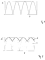
- FIG. 6 shows a comparison of the effective path lengths of the pedals 1a in a known one Pedal crank TK or a crank 1 according to the invention, which is in a pivot point K is stored. While in the crank according to the invention over the entire Path length W force is converted during the keis movement of the well-known pedal crank TK first to overcome the upper and lower dead center T before effective force can be exerted.
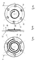
- FIGS. 8a, b, c show a first embodiment of the transition adapter 3.
- Such an adapter essentially consists of a synchronizing plate 12, one Draw roller 13, a base 14, a side plate 15, an inner guide rail 17 and an outer guide rail 18.
- the wheel train 6 leading to the ratchet wheel 7 is attached to a wheel pull bracket 29.
- the crank cable 2 engages on the side plate 15 and is located in one of several switching incisions 26.
- two compression springs 16 for the pull rollers 13 shown.
- FIGS. 9 and 10 These parts are shown in detail in FIGS. 9 and 10.
- Figure 9a shows the synchronizer plate 12, which has a plurality of synchronous cuts 19, which extend at an angle of approximately 45 degrees to the radial direction.
- Figure 9b shows a top view of the pad 14, which is a plurality of radial directed spring incisions 20.
- a section along the line A0-A3 is shown in Figure 9c.
- there is a hole 21 for a compression spring cylinder the roller and a countersink 22 for a compression spring can be seen, the inner circumference with the reference number 23 and the outer circumference with the reference number 24 is designated.
- FIG. 9d shows the side plate 15, which has a plurality of the radially running roller incisions 25 has. These are located in a sector page 28, one Arm side 27 is opposite, in which the switching incisions 26 for the crank cable 2 and the wheel pull bracket 29 for the wheel pull 6.
- Figure 10a shows a top view and a side view of the inner guide rail 17.
- Figure 10b is a side view and a top view of the outer guide rail 18 shown.
- FIG. 10c shows one in different views (folded) Draw roller 13a, which is provided for use without compression spring 16 and a side cylinder 30 and a side cut 31.
- Figure 10d shows different ones Views (folded) of a pull roller 13b for use with compression spring 16, the is set via a spring cylinder 32. This pull roller 13b also has one Side cut 31 and a side cylinder 30.
- FIG. 11a, b, c show a ratchet wheel 7 in different views (folded).
- the Locking wheel 7 is used to roll up the wheel train 6 during the upward direction Movement of the crank 1.
- a coil spring 33 is provided, which on the one hand at a fixed point on the bicycle, on the other hand at an incision 34 a coil spring coupling side 36 attacks.
- the wheel train 6 engages with another incision 34 of a wheel train coupling side 35.
- Each transition adapter is one Ratchet wheel 7 assigned so that both work independently and the cranks 1 can be pressed both simultaneously and alternately.
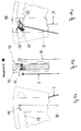
- Figures 12a, 12b show a first switching position of the transition adapter, the automatically taken depending on the resistance at the rear wheel becomes.
- the wheel train 6 exerts a corresponding train on the wheel train holder 29.
- the wheel train 6, which according to FIG. 8c, over the rollers 13a (without compression spring 16), 13b (with compression spring 16) is guided, depending on the number and Strength of the compression springs 16 inwards towards the base 14.
- One such second switching position is shown in Figures 13a, 13b. If the moment resistance becomes smaller again, the compression springs 16 press the rollers 13b and thus the wheel 6 out again.
- the first switching position ( Figure 12) is thus at a minimal torque and maximum speed
- the second switch position ( Figure 13) at maximum torque and minimum speed.
- this automatic Setting is still a manual adjustment to the needs of the Driver possible by the switching incision 26, which is the point of application of the crank cable 2 on the arm side 27 of the side plate 15 represents, manually changed or selected to change the length of the lever arm.
- the rollers 13a, 13b are on the one hand between the side plates 15 in the radial extending roller cuts 25 and on the other hand in the synchronous cuts 19 of the two synchronizer plates 12 out.
- the synchronizing plates 12 pivot by guiding along the inner and outer guide rails 17, 18 if move the rollers radially.
- the synchronizing plates 12 ensure that all rollers always have the same radial position.
- the length of the wheel pull 6 is between the Radzughalterung 29 and the first roller approximately constant, so that with the radial movement of the rollers, no relative movement between them and the wheel train 6 and thus no friction and no path length loss Crank 1 results. Ideally, this is only achieved if the distance between the Radzughalterung 29 and the first roller is infinitely long. In practice you will keep this distance as large as possible and the wheel pull bracket Select 29 so long that the point of attack of the wheel 6 in the middle between the highest and lowest position of the rollers.
- FIGS. 14 and 15 show a second embodiment of the transition adapter 3. This differs from the first embodiment essentially in that that only one pull roller 13b with compression spring 16 is provided, while all the others Pull rollers 13a are moved radially only by the pivoting movement of the synchronizing plate 12 become.
- FIGS. 14a and 14b show a first one corresponding to FIGS. 12a and 12b Switch positions for minimum torque and maximum driving speed, while Figures 15a and 15b a second switch position for maximum Torque and minimum driving speed (according to Figures 13a, 13b). For the rest, the explanations given above in connection were made with Figures 12 and 13.
- FIGS. 16a, 16b, 16c show a third embodiment in different views of the adapter 3.
- the main difference to the first and second embodiment is that according to Figure 16, a manual switch the translation is provided.
- Figure 16a shows a plan view of a switching sector side 37 of a base plate
- FIG. 16c shows a top view of a wheel sector side 38 of the base plate
- a groove arch 42 is located between the two in which the wheel train 6 runs.
- 16a to 16c are the crank cable 2, a shift handle cable 39, a long shift rod 40, a shift cable 41, a cable cover 45, a restraining tension spring 46, a short shift rod 44 and a dental arch 43 are shown.
- Figures 17a 17b, 17c show a detail M in the state in which the clutch is closed (locked), again in different (folded) views, while in Figures 18a, 18b, 18c the same detail is shown, but in which the clutch is separated.
- the clutch has a shift handle 49, which over the shift handle 39th is operated.
- a switching crank 48 becomes pivoted, which lifts a stopcock 47 out of a notch in the dental arch 43, namely against the force of a restraining spring 52.
- a coupling axis 50 on which the crank cable 2 is fastened by means of a crank cable connection 51, can now be moved along the dental arch 43.
- the directional tension spring 46 acts in the opposite direction and guides the rods or the coupling axis 50, which connects the two rods 40, 44, back again.
- Figures 19a, 19b, 19c finally show different views (as with all Views folded) a fourth embodiment of the transition adapter in one first switch position, which is also operated manually.
- the dental arch 43 is located on the Top of a recess of the switching sector side 37 of the base plate.
- the remaining parts and functions are again the same as in Figures 16 to 18.
- Trains are reliable because a train with many threads is a parallel system; if a thread is broken, the train can continue to function. For guidance a groove is sufficient. There are no more friction parts. The efficiency is significantly higher and the lubrication problems are eliminated, so that the wheel clearly becomes cleaner.
- the system according to the invention is cleaner in the case of repair or maintenance and easier. There is no longer a chain or sprocket, the risk pollution and injury is minimal. You can do a lot of lubrication with trains save so that a maintenance-free and clean bike with no effort is feasible.
Landscapes
- Engineering & Computer Science (AREA)
- Chemical & Material Sciences (AREA)
- Combustion & Propulsion (AREA)
- Transportation (AREA)
- Mechanical Engineering (AREA)
- Transmissions By Endless Flexible Members (AREA)
- Automatic Cycles, And Cycles In General (AREA)
- Transmission Devices (AREA)
Applications Claiming Priority (2)
| Application Number | Priority Date | Filing Date | Title |
|---|---|---|---|
| DE1998111491 DE19811491C2 (de) | 1998-03-17 | 1998-03-17 | Zugfahrwerk für Fahrrad |
| DE19811491 | 1998-03-17 |
Publications (2)
| Publication Number | Publication Date |
|---|---|
| EP0943536A2 true EP0943536A2 (fr) | 1999-09-22 |
| EP0943536A3 EP0943536A3 (fr) | 2000-11-02 |
Family
ID=7861152
Family Applications (1)
| Application Number | Title | Priority Date | Filing Date |
|---|---|---|---|
| EP99105514A Withdrawn EP0943536A3 (fr) | 1998-03-17 | 1999-03-17 | Transmission de bicyclette |
Country Status (3)
| Country | Link |
|---|---|
| EP (1) | EP0943536A3 (fr) |
| CN (1) | CN1081152C (fr) |
| DE (1) | DE19811491C2 (fr) |
Cited By (9)
| Publication number | Priority date | Publication date | Assignee | Title |
|---|---|---|---|---|
| DE102008046180A1 (de) | 2008-09-06 | 2010-06-17 | Fichin, Moussei, Dr. Ing. | Fahrzeug |
| KR101101950B1 (ko) * | 2011-11-04 | 2012-01-02 | 이동진 | 왕복 페달식 자전거 |
| CN101559815B (zh) * | 2009-01-19 | 2013-01-02 | 宋来学 | 自行车 |
| CN103253348A (zh) * | 2012-02-21 | 2013-08-21 | 师围田 | 无链省力自行车设置 |
| CN103318366A (zh) * | 2012-03-24 | 2013-09-25 | 宁波市镇海捷登应用技术研究所 | 一种脚踏自行车 |
| WO2015090319A1 (fr) * | 2013-12-19 | 2015-06-25 | J.M.J. Holding Aps | Transmission pour véhicule à propulsion humaine (hpv) et véhicule de ce type |
| WO2018034466A1 (fr) * | 2016-08-17 | 2018-02-22 | 홍석수 | Vélo |
| US11052965B2 (en) | 2016-08-17 | 2021-07-06 | Seok Su Hong | Bicycle |
| CN116296970A (zh) * | 2023-05-22 | 2023-06-23 | 山东工程职业技术大学 | 一种汽车链条传动磨损试验设备及方法 |
Families Citing this family (9)
| Publication number | Priority date | Publication date | Assignee | Title |
|---|---|---|---|---|
| CN100391782C (zh) * | 2005-09-30 | 2008-06-04 | 邓小荣 | 中轴前移无链自行车 |
| ES2356432B1 (es) * | 2008-03-31 | 2012-03-15 | Joaqu�?N De Marimón Culell | Mecanismo de transmisión autom�?tico para veh�?culos. |
| GB2563456B (en) * | 2017-06-17 | 2020-07-29 | James Jeffs Michael | Evolving sprocket |
| CN109421892A (zh) * | 2017-08-19 | 2019-03-05 | 黄善媛 | 两单向轴承分组储带同轴互动往返动力转单向旋转动力装置 |
| CN108001606A (zh) * | 2017-12-22 | 2018-05-08 | 东营市海天石油科技有限责任公司 | 一种省力变速自行车 |
| CN109484561B (zh) * | 2018-12-03 | 2020-06-30 | 王招奇 | 拉索力矩传递机构和踏板车 |
| CN112046670A (zh) * | 2020-08-19 | 2020-12-08 | 陈波 | 一种省力自行车 |
| CN113715955B (zh) * | 2021-09-13 | 2023-01-10 | 昆山德钜源运动科技有限公司 | 一种无级变速自行车牙盘 |
| CN115123437B (zh) * | 2022-08-09 | 2025-12-02 | 强毅 | 一种以杠杆发力储能发条鼓自行车 |
Citations (1)
| Publication number | Priority date | Publication date | Assignee | Title |
|---|---|---|---|---|
| DE426146C (de) | 1923-02-27 | 1926-03-02 | Jakob Bosshard | Trethebelwechselgetriebe |
Family Cites Families (16)
| Publication number | Priority date | Publication date | Assignee | Title |
|---|---|---|---|---|
| DE116162C (fr) * | ||||
| DE92777C (fr) * | ||||
| FR322810A (fr) * | 1902-07-07 | 1903-02-13 | Gathier | Mécanisme de propulsion pour cycles |
| FR379091A (fr) * | 1907-06-10 | 1907-10-24 | Yves Le Roux | Nouveau système de bicyclette à leviers, à pédales oscillantes et réversibles, à traction constante et continue et à développement réglable instantanément et à volonté, mettant momentanément hors de service tous véhicules à avancement pédalier |
| FR387677A (fr) * | 1908-02-29 | 1908-07-20 | Jules Alfred Descroix | Mécanisme de changement de vitesse pour bicyclettes, voitures automobiles et machines diverses |
| CH227063A (fr) * | 1942-07-30 | 1943-05-15 | Ems Eugene | Bicyclette. |
| IT454674A (fr) * | 1945-09-20 | |||
| DE1001913B (de) * | 1953-08-12 | 1957-01-31 | Anton Ranger | Getriebe, insbesondere fuer Fahrradantriebe |
| US4129044A (en) * | 1977-05-19 | 1978-12-12 | Erickson Marlo W V | Variable gear ratio chain drive system for bicycles |
| US4741546A (en) * | 1984-03-27 | 1988-05-03 | Reswick James B | Torque responsive automatic bicycle transmission |
| GB2160271A (en) * | 1984-06-13 | 1985-12-18 | O Hea Adrian Ralph | Variable-ratio transmission |
| CN85203897U (zh) * | 1985-09-11 | 1986-05-28 | 张开延 | 踏板式自行车 |
| US5242182A (en) * | 1991-12-09 | 1993-09-07 | Bezerra Wilson X | Bicycle and the like |
| DE4318648C1 (de) * | 1993-06-04 | 1994-07-14 | Kraemer Hubert Dipl Ing Fh | Riementrieb mit selbttätiger stufenloser Übersetzungsänderung, insbesondere für Fahrräder |
| DE19507011A1 (de) * | 1995-02-28 | 1996-09-05 | Matthias Herrmann | Antriebsvorrichtung für Fahrräder (einspurige, zweispurige + Liegeräder) |
| DE19641241A1 (de) * | 1996-10-07 | 1997-07-03 | Kludszuweit Alfred | Antriebseinheit für Fahrräder und Maschinen mit angenäherter Geradführung des Kraftangriffspunktes |
-
1998
- 1998-03-17 DE DE1998111491 patent/DE19811491C2/de not_active Expired - Fee Related
-
1999
- 1999-03-16 CN CN99103328A patent/CN1081152C/zh not_active Expired - Fee Related
- 1999-03-17 EP EP99105514A patent/EP0943536A3/fr not_active Withdrawn
Patent Citations (1)
| Publication number | Priority date | Publication date | Assignee | Title |
|---|---|---|---|---|
| DE426146C (de) | 1923-02-27 | 1926-03-02 | Jakob Bosshard | Trethebelwechselgetriebe |
Cited By (10)
| Publication number | Priority date | Publication date | Assignee | Title |
|---|---|---|---|---|
| DE102008046180A1 (de) | 2008-09-06 | 2010-06-17 | Fichin, Moussei, Dr. Ing. | Fahrzeug |
| CN101559815B (zh) * | 2009-01-19 | 2013-01-02 | 宋来学 | 自行车 |
| KR101101950B1 (ko) * | 2011-11-04 | 2012-01-02 | 이동진 | 왕복 페달식 자전거 |
| CN103253348A (zh) * | 2012-02-21 | 2013-08-21 | 师围田 | 无链省力自行车设置 |
| CN103318366A (zh) * | 2012-03-24 | 2013-09-25 | 宁波市镇海捷登应用技术研究所 | 一种脚踏自行车 |
| WO2015090319A1 (fr) * | 2013-12-19 | 2015-06-25 | J.M.J. Holding Aps | Transmission pour véhicule à propulsion humaine (hpv) et véhicule de ce type |
| US10239577B2 (en) | 2013-12-19 | 2019-03-26 | J.M.J. Holdings APS | Transmission for a human powered vehicle (HPV) and such vehicle |
| WO2018034466A1 (fr) * | 2016-08-17 | 2018-02-22 | 홍석수 | Vélo |
| US11052965B2 (en) | 2016-08-17 | 2021-07-06 | Seok Su Hong | Bicycle |
| CN116296970A (zh) * | 2023-05-22 | 2023-06-23 | 山东工程职业技术大学 | 一种汽车链条传动磨损试验设备及方法 |
Also Published As
| Publication number | Publication date |
|---|---|
| DE19811491A1 (de) | 1999-03-18 |
| CN1081152C (zh) | 2002-03-20 |
| CN1229749A (zh) | 1999-09-29 |
| EP0943536A3 (fr) | 2000-11-02 |
| DE19811491C2 (de) | 1999-09-23 |
Similar Documents
| Publication | Publication Date | Title |
|---|---|---|
| DE2334091A1 (de) | Bremsvorrichtung | |
| DE3518868A1 (de) | Motorisierte betaetigung fuer eine ankoppelvorrichtung, wie z.b. kupplung, regelgetriebe, bremse oder dergl. | |
| DE19811491C2 (de) | Zugfahrwerk für Fahrrad | |
| EP0738643B1 (fr) | Unité de pince de frein pour freins à disque pour véhicule, notamment pour véhicules ferroviaires | |
| DE4123476C2 (fr) | ||
| DE102005007205B3 (de) | Elektromotorischer Linearantrieb | |
| DE102015114335B4 (de) | Schienenverkehrssystem zum Vereinzeln und Umleiten von Schienenfahrzeugen | |
| DE102008006242A1 (de) | Tretroller, Skateboard oder ähnliches Fahrzeug mit einstellbarer Lenkung | |
| DE10140075B4 (de) | Zuspanneinrichtung für Radbremsen | |
| EP1817222A2 (fr) | Systeme de commande manuelle d'une roue guidee | |
| DE1477827A1 (de) | Vorschubgetriebe fuer Werkzeugmaschinen | |
| EP0603843B1 (fr) | Dispositif d'entraînement pour véhicules | |
| DE3700546C2 (fr) | ||
| DE102019107974A1 (de) | Schneidwerk für eine landwirtschaftliche Erntemaschine | |
| DE4137046C2 (de) | Getriebe für eine Fitnessmaschine | |
| DE2648083C2 (de) | Sicherheitseinrichtung für Fahrzeuge im Mitgängerbetrieb | |
| DE102004023091B4 (de) | Tretkurbelantrieb für durch Muskelkraft betriebene Geräte, insbesondere Fahrzeuge und Trainingsgeräte | |
| EP0090918A2 (fr) | Levier à pied pour motocyclette | |
| DE102020117558A1 (de) | Roller mit Hinterradschwinge | |
| WO2005034686A1 (fr) | Actionneur | |
| DE19529903C2 (de) | Fahrradschaltung | |
| DE202005006169U1 (de) | Getriebe mit stufenlos einstellbarer Übersetzung | |
| DE202008018074U1 (de) | Tretroller, Skateboard oder ähnliches Fahrzeug mit einstellbarer Lenkung | |
| DE7400681U (de) | Auflaufbremsanlage für Anhänger | |
| DE1475415A1 (de) | Selbsttaetig wirkende Nachstellvorrichtung fuer dem Verschleiss unterworfene Maschinenelemente,insbesondere fuer Reibungskupplungen |
Legal Events
| Date | Code | Title | Description |
|---|---|---|---|
| PUAI | Public reference made under article 153(3) epc to a published international application that has entered the european phase |
Free format text: ORIGINAL CODE: 0009012 |
|
| AK | Designated contracting states |
Kind code of ref document: A2 Designated state(s): DE FR GB IT NL |
|
| AX | Request for extension of the european patent |
Free format text: AL;LT;LV;MK;RO;SI |
|
| PUAL | Search report despatched |
Free format text: ORIGINAL CODE: 0009013 |
|
| AK | Designated contracting states |
Kind code of ref document: A3 Designated state(s): AT BE CH CY DE DK ES FI FR GB GR IE IT LI LU MC NL PT SE |
|
| AX | Request for extension of the european patent |
Free format text: AL;LT;LV;MK;RO;SI |
|
| 17P | Request for examination filed |
Effective date: 20010427 |
|
| AKX | Designation fees paid |
Free format text: DE FR GB IT NL |
|
| 17Q | First examination report despatched |
Effective date: 20030819 |
|
| STAA | Information on the status of an ep patent application or granted ep patent |
Free format text: STATUS: THE APPLICATION IS DEEMED TO BE WITHDRAWN |
|
| 18D | Application deemed to be withdrawn |
Effective date: 20031001 |