EP0943577A2 - Verbindungslasche für die Leiterelemente eines Bauaufzuges oder dgl. - Google Patents
Verbindungslasche für die Leiterelemente eines Bauaufzuges oder dgl. Download PDFInfo
- Publication number
- EP0943577A2 EP0943577A2 EP99104614A EP99104614A EP0943577A2 EP 0943577 A2 EP0943577 A2 EP 0943577A2 EP 99104614 A EP99104614 A EP 99104614A EP 99104614 A EP99104614 A EP 99104614A EP 0943577 A2 EP0943577 A2 EP 0943577A2
- Authority
- EP
- European Patent Office
- Prior art keywords
- tab
- edge
- connecting strap
- insertable
- conductor
- Prior art date
- Legal status (The legal status is an assumption and is not a legal conclusion. Google has not performed a legal analysis and makes no representation as to the accuracy of the status listed.)
- Granted
Links
Images


Classifications
-
- B—PERFORMING OPERATIONS; TRANSPORTING
- B66—HOISTING; LIFTING; HAULING
- B66B—ELEVATORS; ESCALATORS OR MOVING WALKWAYS
- B66B7/00—Other common features of elevators
- B66B7/02—Guideways; Guides
-
- B—PERFORMING OPERATIONS; TRANSPORTING
- B66—HOISTING; LIFTING; HAULING
- B66B—ELEVATORS; ESCALATORS OR MOVING WALKWAYS
- B66B9/00—Kinds or types of lifts in, or associated with, buildings or other structures
- B66B9/16—Mobile or transportable lifts specially adapted to be shifted from one part of a building or other structure to another part or to another building or structure
- B66B9/187—Mobile or transportable lifts specially adapted to be shifted from one part of a building or other structure to another part or to another building or structure with a liftway specially adapted for temporary connection to a building or other structure
Definitions
- the invention relates to a connecting tab for the pluggable conductor elements a construction elevator or the like. According to the preamble of the claim 1.
- each conductor element has that two in parallel distance, connected by several cross struts
- the other half the connecting tab protrudes from the relevant end of the profile element out and serves as a coupling part, which, if ex. the first conductor element the construction elevator ladder has been set up when the following ladder element is attached insertable into the free end of the first conductor element and there, likewise by means of usual connecting means, ex. in the form of screws or Like., Can be determined.
- the invention is therefore based on the object to eliminate the described Disadvantages of the connecting tabs for the pluggable conductor elements a construction elevator or the like. In such a way that the equipped with it Ladder elements easy and quick to assemble and in particular in the same way are also removable.
- the invention is based on the essential idea of the connecting tabs to design the conductor elements in such a way that the respective plug end deviates from the usual rectangular shape when it is a light, uniform, unimpeded insertion into the relevant free end of the to be coupled allows other conductor element and thus an equally friction as well trouble-free extraction, i.e. Disassembly allowed.
- the invention provides that the connecting tab at its insertable end at least over part of its boundary edge has a course deviating inwards from the - usual - straight line.
- boundary edge of insertable tab ends which otherwise when connecting or disconnecting each two conductor elements causes a disturbance caused by friction or the like, provided with a rounded course or designed such that the relevant Boundary edge or a part thereof an angled to the longitudinal tab axis Boundary edge forms.
- the inward deviating from the straight line Edge course over at least part of one of the two long sides Boundary edges and / or the front edge of the insertable Tab end extends.
- the relevant boundary edge have a rounded profile and / or angled or oblique run.
- the edge course is the insertable tab end from a combination of the aforementioned rounding and the angled edge course formed, in such a way that the insertable Tab end at its one longitudinal boundary edge the usual straight course, parallel to the longitudinal tab axis, while the other longitudinal boundary edge together with the front boundary edge of the insertable tab end formed in the sense of the invention is that in principle an angle to the longitudinal axis of the tab, preferably Boundary edge running at an angle of 30 - 60 ° to the longitudinal axis of the plate is provided at the transition between the plug end and the holder end the connecting tab turns into a curve.
- the decisive advantage is that inserting the connecting tabs of the one conductor element into the other conductor element designed trouble-free, uniform and almost smoothly, so that the time and effort associated with the crest of two ladder elements is significantly minimized.
- the connecting strap is preferably made of a different material than the conductor elements. So are the connecting tabs For example, made of steel, while the conductor elements for reasons of weight saving usually consist of aluminum. This material difference has a different friction factor, so that too this further minimizes the risk of seizing.
- the connecting tab expediently points at the transition between it insertable end and its holder end a retracted edge part on. This is preferably part-circular, so that this also especially when dismantling the conductor elements, the tilting of one conductor element compared to the other conductor element - and thus the total Disassembly process - is further facilitated.
- a load handler such as ex. a conveyor basket, a transport platform etc.
- the conductor elements 1, 2 are basically identical.
- Each connecting tab 3 is formed in the manner shown in the drawing and has an insertable end 6 and a holder end 7.
- the about half of the longitudinal extent of the connecting tab 3 Bracket end 7 is at one end of each conductor element 2 or 1 - in the illustrated Embodiment at each lower end of the conductor element 2 - attached. For this purpose, it is inserted into the lower end of the conductor element 2 and there using conventional fasteners, ex. Screws, rivets etc., fixed.
- both the holder end 7 has for this purpose the connecting tab 3 as well as each relevant lower end of the conductor element 2 or 1 through holes 8, which are spaced from each other in the Longitudinal axis 12 of the conductor elements 1, 2 or the connecting tab 3 is arranged and, when they have been brought into alignment with one another, by the Lanyards are enforced.
- the bracket end is 7th each connecting strap 3 firmly and immovably in the lower end in question the conductor elements 2, 1 set.
- each connecting tab 3 is used for insertion into the relevant one upper end of the further conductor element 1 to be coupled.
- insertable tab end 6 is a - usual - longitudinal boundary edge 9, but configured in such a manner on its remaining boundary edges 10, 11 is that the front edge 10, which is otherwise in the state the technology runs transversely to the longitudinal tab axis 12, has an angular course, while that boundary edge 11 that the to the tab longitudinal axis 12th parallel longitudinal boundary edge 9 is opposite, a rounded Has course and accordingly uniform in the angular boundary edge 10th transforms.
- the angle ⁇ that the inclined boundary edge 10 to Longitudinal longitudinal axis 12 forms can be in the range between 30 - 60 ° and is in the illustrated embodiment about 45 °.
- each connecting tab 3 has approximately the shape of the sword or keel of a sailboat, so that, as from the Drawing can be seen, the insertable tab end 6 to the tab axis 12 has asymmetrical edge course 9, 10, 11.
- each connecting link 3 is symmetrical to the longitudinal axis 12 of the link
- the total insertable tab end 3 at least over part of its boundary edges 9, 10, 11 one of the respective straight line (longitudinal axis 12 or transverse axis to this) has an inwardly deviating course.
- the connecting tab 3 On its one long side, the connecting tab 3 has at the transition between its insertable end 6 and its holder end 7 a retracted Edge part 13. This is part-circular and carries in the from the drawing obvious way to facilitate insertion or removal of the Connecting tab 3 into the end of the conductor element 1 to be coupled or 2 at.
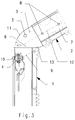
- Fig. 1 shows the state of the fixed at each lower end of the conductor element 2 Connection tab 3, in which it with its plug end 6 in the respective inserted upper end of the lower conductor element 1 and there by means of the connecting means 4, in the mutually aligned through holes 5 of connecting tab 3 and intervening conductor element 1 is fixed.
- the assembly process is just as smooth and simple, so that overall, a considerable amount of time and effort is saved.
Landscapes
- Engineering & Computer Science (AREA)
- Structural Engineering (AREA)
- Civil Engineering (AREA)
- Transportation (AREA)
- Automation & Control Theory (AREA)
- Ladders (AREA)
- Connections Effected By Soldering, Adhesion, Or Permanent Deformation (AREA)
- Elimination Of Static Electricity (AREA)
- Lift-Guide Devices, And Elevator Ropes And Cables (AREA)
Abstract
Description
- Fig. 1
- in Seitenansicht teilweise geschnitten zwei ineinander gesteckte und mittels der Verbindungslasche gemäß der Erfindung verbundene Leiterelemente eines Bauaufzuges oder dgl.;
- Fig. 2
- die beiden Leiterelemente in einem ersten Schritt der Demontage sowie
- Fig. 3
- in einem weiteren Schritt der Demontage.
Claims (8)
- Verbindungslasche für die zusammensteckbaren Leiterelemente (1, 2) eines Bauaufzuges oder dgl., wobei die Leiterelemente (1, 2) jeweils wenigstens zwei im Abstand voneinander verlaufende, durch wenigstens eine Querstrebe verbundene Profilelemente aufweisen, an deren einem Ende jeweils eine Verbindungslasche (3) vorgesehen ist, die in das andere Ende eines anzukuppelnden weiteren Leiterelementes (1) einsteckbar und dort durch Verbindungsmittel (4), die in miteinander fluchtende Durchgangslöcher (5) der Verbindungslaschen (3) und der Leiterelemente (1, 2) eingreifen, festlegbar ist,
dadurch gekennzeichnet,
daß die Verbindungslasche (3) an ihrem einsteckbaren Ende (6) wenigstens über einen Teil ihrer Begrenzungskante (9, 10, 11) einen von der Geraden nach innen abweichenden Verlauf aufweist. - Verbindungslasche nach Anspruch 1, dadurch gekennzeichnet, daß sich der von der Geraden nach innen abweichende Kantenverlauf über wenigstens einen Teil einer der beiden längsseitigen Begrenzungskanten (11) und/oder der stirnseitigen Begrenzungskante (10) des einsteckbaren Laschenendes (6) erstreckt.
- Verbindungslasche nach Anspruch 1 oder 2, dadurch gekennzeichnet, daß der von der Geraden nach innen abweichende Kantenverlauf eine abgerundete Begrenzungskante (11) bildet.
- Verbindungslasche nach einem der vorhergehenden Ansprüche, dadurch gekennzeichnet, daß der von der Geraden nach innen abweichende Kantenverlauf eine zur Laschenlängsachse (12) winklige Begrenzungskante (10) bildet.
- Verbindungslasche nach Anspruch 4, dadurch gekennzeichnet, daß die winklige Begrenzungskante (10) im Winkel von 30 - 60° zur Laschenlängsachse (12) verläuft.
- Verbindungslasche nach einem der vorhergehenden Ansprüche, dadurch gekennzeichnet, daß das einsteckbare Laschenende (6) einen zur Laschenlängsachse (12) asymmetrischen Kantenverlauf aufweist.
- Verbindungslasche nach einem der vorhergehenden Ansprüche, dadurch gekennzeichnet, daß sie am Übergang zwischen ihrem einsteckbaren Ende (6) und ihrem Halterungsende (7) einen, insbesondere teilkreisförmig, eingezogenen Kantenteil (13) aufweist.
- Verbindungslasche nach einem der vorhergehenden Ansprüche, dadurch gekennzeichnet, daß sie aus einem anderen Material als die Leiterelemente (1, 2) besteht.
Applications Claiming Priority (2)
| Application Number | Priority Date | Filing Date | Title |
|---|---|---|---|
| DE29804704U | 1998-03-16 | ||
| DE29804704U DE29804704U1 (de) | 1998-03-16 | 1998-03-16 | Verbindungslasche für die Leiterelemente eines Bauaufzuges o.dgl. |
Publications (3)
| Publication Number | Publication Date |
|---|---|
| EP0943577A2 true EP0943577A2 (de) | 1999-09-22 |
| EP0943577A3 EP0943577A3 (de) | 2001-07-11 |
| EP0943577B1 EP0943577B1 (de) | 2003-06-18 |
Family
ID=8054238
Family Applications (1)
| Application Number | Title | Priority Date | Filing Date |
|---|---|---|---|
| EP99104614A Expired - Lifetime EP0943577B1 (de) | 1998-03-16 | 1999-03-09 | Verbindungslasche für die Leiterelemente eines Bauaufzuges oder dgl. |
Country Status (3)
| Country | Link |
|---|---|
| EP (1) | EP0943577B1 (de) |
| AT (1) | ATE243159T1 (de) |
| DE (2) | DE29804704U1 (de) |
Family Cites Families (7)
| Publication number | Priority date | Publication date | Assignee | Title |
|---|---|---|---|---|
| US2375409A (en) | 1942-07-27 | 1945-05-08 | Glitsch & Sons Fritz W | Fastening device |
| DE3035801C2 (de) * | 1980-09-23 | 1984-07-05 | Maschinenfabrik Hermann Paus GmbH, 4448 Emsbüren | Schrägaufzug zum Transport von Lasten |
| FR2565286B1 (fr) | 1984-06-05 | 1987-09-11 | Bezard Paul | Echelle de securite de chantier universelle |
| SE469719B (sv) * | 1991-05-02 | 1993-08-30 | Percus Ab | Transportoer eller hissanordning med en styrd fram- och aatergaaende drivkedja |
| DE4201223A1 (de) | 1992-01-18 | 1993-07-22 | Schueco Int Kg | Halterung fuer fuellungsplatten, drahtgitter, drahtgewebe o. dgl. in durch systemprofilschienen begrenzten rahmenfeldern |
| DE4423430A1 (de) | 1994-07-05 | 1996-01-11 | Distel Ulrich Dipl Forsting Fh | Steckverbindung zum Verbinden zweier Teile (z. B. Leitern) |
| DE19614042A1 (de) * | 1996-04-10 | 1997-10-16 | Hermann Paus Maschinenfabrik G | Schrägaufzug |
-
1998
- 1998-03-16 DE DE29804704U patent/DE29804704U1/de not_active Expired - Lifetime
-
1999
- 1999-03-09 EP EP99104614A patent/EP0943577B1/de not_active Expired - Lifetime
- 1999-03-09 AT AT99104614T patent/ATE243159T1/de not_active IP Right Cessation
- 1999-03-09 DE DE59905967T patent/DE59905967D1/de not_active Expired - Fee Related
Also Published As
| Publication number | Publication date |
|---|---|
| EP0943577B1 (de) | 2003-06-18 |
| DE59905967D1 (de) | 2003-07-24 |
| ATE243159T1 (de) | 2003-07-15 |
| EP0943577A3 (de) | 2001-07-11 |
| DE29804704U1 (de) | 1998-06-18 |
Similar Documents
| Publication | Publication Date | Title |
|---|---|---|
| DE69100219T2 (de) | Verbindungsstück für längliche Elemente. | |
| DE2449124B2 (de) | Verbindungsvorrichtung für Gerüstelemente | |
| DE2704398B2 (de) | Aus Ständern und Riegeln zusammensetzbares Gerüst | |
| DE4324871A1 (de) | Gleitbrett | |
| DE8703695U1 (de) | Bauelementensatz für einen Gehäuserahmen | |
| EP0694659B1 (de) | Traggerüst | |
| DE2822676C2 (de) | Verbindungsvorrichtung für Gerüstelemente | |
| DE2722425C2 (de) | Verbindung der Stützen eines metallischen Traggerüstes | |
| EP0004374A1 (de) | Vorrichtung zum Verbinden von zwei Profilstäben | |
| DE3142572C2 (de) | Vorrichtung zum lösbaren Verbinden von Seilenden, insbesondere von Seilen bei umlaufenden Seiltrieben, Seilförderern oder Aufhängungen | |
| EP0943577B1 (de) | Verbindungslasche für die Leiterelemente eines Bauaufzuges oder dgl. | |
| DE2446927C3 (de) | Großflächenschalung mit verschieden gekrümmten Flächen | |
| DE3812179C2 (de) | ||
| DE1759497C3 (de) | Verbindungselement für die Herstellung einer Spannverbindung von Wandteilen oder anderen Teilen mit Profilschienen | |
| DE29813088U1 (de) | Montagevorrichtung | |
| EP0430308A2 (de) | Metallstandgerüst für Bauwerke | |
| EP2226272B1 (de) | Regalsystem | |
| DE4343433C2 (de) | Gestell für Bürotisch | |
| AT328168B (de) | Spannelement zum befestigen, verbinden und/oder ausrichten von schalungsteilen | |
| CH651622A5 (en) | Shuttering which is intended for the building industry | |
| DE29500190U1 (de) | Adapterelement für Gerüstgruppen | |
| DE591069C (de) | Riegelstange mit zueinander verschiebbaren Klemmteilen fuer Baugerueste | |
| DE202023100295U1 (de) | Regalsystemverbinder | |
| DE10107889A1 (de) | Ballastgewicht für ein Stand- oder Fahrgerüst | |
| DE8423109U1 (de) | Verbindungsmittel für Schalungstafeln |
Legal Events
| Date | Code | Title | Description |
|---|---|---|---|
| PUAI | Public reference made under article 153(3) epc to a published international application that has entered the european phase |
Free format text: ORIGINAL CODE: 0009012 |
|
| AK | Designated contracting states |
Kind code of ref document: A2 Designated state(s): AT BE CH CY DE DK ES FI FR GB GR IE IT LI LU MC NL PT SE |
|
| AX | Request for extension of the european patent |
Free format text: AL;LT;LV;MK;RO;SI |
|
| PUAL | Search report despatched |
Free format text: ORIGINAL CODE: 0009013 |
|
| AK | Designated contracting states |
Kind code of ref document: A3 Designated state(s): AT BE CH CY DE DK ES FI FR GB GR IE IT LI LU MC NL PT SE |
|
| AX | Request for extension of the european patent |
Free format text: AL;LT;LV;MK;RO;SI |
|
| RAP1 | Party data changed (applicant data changed or rights of an application transferred) |
Owner name: GEDA-DECHENTREITER GMBH & CO. KG. |
|
| 17P | Request for examination filed |
Effective date: 20010625 |
|
| AKX | Designation fees paid |
Free format text: AT BE CH CY DE DK ES FI FR GB GR IE IT LI LU MC NL PT SE |
|
| AXX | Extension fees paid |
Free format text: AL PAYMENT 20011031;LT PAYMENT 20011031;LV PAYMENT 20011031;SI PAYMENT 20011031 |
|
| 17Q | First examination report despatched |
Effective date: 20020321 |
|
| GRAH | Despatch of communication of intention to grant a patent |
Free format text: ORIGINAL CODE: EPIDOS IGRA |
|
| GRAH | Despatch of communication of intention to grant a patent |
Free format text: ORIGINAL CODE: EPIDOS IGRA |
|
| GRAA | (expected) grant |
Free format text: ORIGINAL CODE: 0009210 |
|
| AK | Designated contracting states |
Designated state(s): AT BE CH CY DE DK ES FI FR GB GR IE IT LI LU MC NL PT SE |
|
| AX | Request for extension of the european patent |
Extension state: AL LT LV SI |
|
| PG25 | Lapsed in a contracting state [announced via postgrant information from national office to epo] |
Ref country code: NL Free format text: LAPSE BECAUSE OF FAILURE TO SUBMIT A TRANSLATION OF THE DESCRIPTION OR TO PAY THE FEE WITHIN THE PRESCRIBED TIME-LIMIT Effective date: 20030618 Ref country code: IT Free format text: LAPSE BECAUSE OF FAILURE TO SUBMIT A TRANSLATION OF THE DESCRIPTION OR TO PAY THE FEE WITHIN THE PRESCRIBED TIME-LIMIT;WARNING: LAPSES OF ITALIAN PATENTS WITH EFFECTIVE DATE BEFORE 2007 MAY HAVE OCCURRED AT ANY TIME BEFORE 2007. THE CORRECT EFFECTIVE DATE MAY BE DIFFERENT FROM THE ONE RECORDED. Effective date: 20030618 Ref country code: IE Free format text: LAPSE BECAUSE OF FAILURE TO SUBMIT A TRANSLATION OF THE DESCRIPTION OR TO PAY THE FEE WITHIN THE PRESCRIBED TIME-LIMIT Effective date: 20030618 Ref country code: GB Free format text: LAPSE BECAUSE OF FAILURE TO SUBMIT A TRANSLATION OF THE DESCRIPTION OR TO PAY THE FEE WITHIN THE PRESCRIBED TIME-LIMIT Effective date: 20030618 Ref country code: FR Free format text: LAPSE BECAUSE OF FAILURE TO SUBMIT A TRANSLATION OF THE DESCRIPTION OR TO PAY THE FEE WITHIN THE PRESCRIBED TIME-LIMIT Effective date: 20030618 Ref country code: FI Free format text: LAPSE BECAUSE OF FAILURE TO SUBMIT A TRANSLATION OF THE DESCRIPTION OR TO PAY THE FEE WITHIN THE PRESCRIBED TIME-LIMIT Effective date: 20030618 Ref country code: CY Free format text: LAPSE BECAUSE OF FAILURE TO SUBMIT A TRANSLATION OF THE DESCRIPTION OR TO PAY THE FEE WITHIN THE PRESCRIBED TIME-LIMIT Effective date: 20030618 |
|
| REG | Reference to a national code |
Ref country code: GB Ref legal event code: FG4D Free format text: NOT ENGLISH |
|
| REG | Reference to a national code |
Ref country code: CH Ref legal event code: EP |
|
| REG | Reference to a national code |
Ref country code: IE Ref legal event code: FG4D Free format text: GERMAN |
|
| REF | Corresponds to: |
Ref document number: 59905967 Country of ref document: DE Date of ref document: 20030724 Kind code of ref document: P |
|
| PG25 | Lapsed in a contracting state [announced via postgrant information from national office to epo] |
Ref country code: SE Free format text: LAPSE BECAUSE OF FAILURE TO SUBMIT A TRANSLATION OF THE DESCRIPTION OR TO PAY THE FEE WITHIN THE PRESCRIBED TIME-LIMIT Effective date: 20030918 Ref country code: PT Free format text: LAPSE BECAUSE OF FAILURE TO SUBMIT A TRANSLATION OF THE DESCRIPTION OR TO PAY THE FEE WITHIN THE PRESCRIBED TIME-LIMIT Effective date: 20030918 Ref country code: GR Free format text: LAPSE BECAUSE OF FAILURE TO SUBMIT A TRANSLATION OF THE DESCRIPTION OR TO PAY THE FEE WITHIN THE PRESCRIBED TIME-LIMIT Effective date: 20030918 Ref country code: DK Free format text: LAPSE BECAUSE OF FAILURE TO SUBMIT A TRANSLATION OF THE DESCRIPTION OR TO PAY THE FEE WITHIN THE PRESCRIBED TIME-LIMIT Effective date: 20030918 |
|
| PG25 | Lapsed in a contracting state [announced via postgrant information from national office to epo] |
Ref country code: ES Free format text: LAPSE BECAUSE OF FAILURE TO SUBMIT A TRANSLATION OF THE DESCRIPTION OR TO PAY THE FEE WITHIN THE PRESCRIBED TIME-LIMIT Effective date: 20030929 |
|
| LTIE | Lt: invalidation of european patent or patent extension |
Effective date: 20030618 |
|
| NLV1 | Nl: lapsed or annulled due to failure to fulfill the requirements of art. 29p and 29m of the patents act | ||
| GBV | Gb: ep patent (uk) treated as always having been void in accordance with gb section 77(7)/1977 [no translation filed] |
Effective date: 20030618 |
|
| REG | Reference to a national code |
Ref country code: IE Ref legal event code: FD4D |
|
| PG25 | Lapsed in a contracting state [announced via postgrant information from national office to epo] |
Ref country code: LU Free format text: LAPSE BECAUSE OF NON-PAYMENT OF DUE FEES Effective date: 20040309 Ref country code: AT Free format text: LAPSE BECAUSE OF NON-PAYMENT OF DUE FEES Effective date: 20040309 |
|
| PG25 | Lapsed in a contracting state [announced via postgrant information from national office to epo] |
Ref country code: MC Free format text: LAPSE BECAUSE OF NON-PAYMENT OF DUE FEES Effective date: 20040331 Ref country code: LI Free format text: LAPSE BECAUSE OF NON-PAYMENT OF DUE FEES Effective date: 20040331 Ref country code: CH Free format text: LAPSE BECAUSE OF NON-PAYMENT OF DUE FEES Effective date: 20040331 Ref country code: BE Free format text: LAPSE BECAUSE OF NON-PAYMENT OF DUE FEES Effective date: 20040331 |
|
| PLBE | No opposition filed within time limit |
Free format text: ORIGINAL CODE: 0009261 |
|
| STAA | Information on the status of an ep patent application or granted ep patent |
Free format text: STATUS: NO OPPOSITION FILED WITHIN TIME LIMIT |
|
| 26N | No opposition filed |
Effective date: 20040319 |
|
| EN | Fr: translation not filed | ||
| BERE | Be: lapsed |
Owner name: *GEDA-DECHENTREITER G.M.B.H. & CO. K.G. Effective date: 20040331 |
|
| PG25 | Lapsed in a contracting state [announced via postgrant information from national office to epo] |
Ref country code: DE Free format text: LAPSE BECAUSE OF NON-PAYMENT OF DUE FEES Effective date: 20041001 |
|
| REG | Reference to a national code |
Ref country code: CH Ref legal event code: PL |