EP0943593B1 - Formkörper aus einer elektrisch leitfähigen Keramik sowie Verfahren zur Herstellung von Kontaktbereichen an solchen Formkörpern - Google Patents
Formkörper aus einer elektrisch leitfähigen Keramik sowie Verfahren zur Herstellung von Kontaktbereichen an solchen Formkörpern Download PDFInfo
- Publication number
- EP0943593B1 EP0943593B1 EP99103651A EP99103651A EP0943593B1 EP 0943593 B1 EP0943593 B1 EP 0943593B1 EP 99103651 A EP99103651 A EP 99103651A EP 99103651 A EP99103651 A EP 99103651A EP 0943593 B1 EP0943593 B1 EP 0943593B1
- Authority
- EP
- European Patent Office
- Prior art keywords
- metal
- electrically conductive
- infiltrated
- ceramic
- molded part
- Prior art date
- Legal status (The legal status is an assumption and is not a legal conclusion. Google has not performed a legal analysis and makes no representation as to the accuracy of the status listed.)
- Expired - Lifetime
Links
Images
Classifications
-
- F—MECHANICAL ENGINEERING; LIGHTING; HEATING; WEAPONS; BLASTING
- F01—MACHINES OR ENGINES IN GENERAL; ENGINE PLANTS IN GENERAL; STEAM ENGINES
- F01N—GAS-FLOW SILENCERS OR EXHAUST APPARATUS FOR MACHINES OR ENGINES IN GENERAL; GAS-FLOW SILENCERS OR EXHAUST APPARATUS FOR INTERNAL-COMBUSTION ENGINES
- F01N3/00—Exhaust or silencing apparatus having means for purifying, rendering innocuous, or otherwise treating exhaust
- F01N3/08—Exhaust or silencing apparatus having means for purifying, rendering innocuous, or otherwise treating exhaust for rendering innocuous
- F01N3/10—Exhaust or silencing apparatus having means for purifying, rendering innocuous, or otherwise treating exhaust for rendering innocuous by thermal or catalytic conversion of noxious components of exhaust
- F01N3/24—Exhaust or silencing apparatus having means for purifying, rendering innocuous, or otherwise treating exhaust for rendering innocuous by thermal or catalytic conversion of noxious components of exhaust characterised by constructional aspects of converting apparatus
- F01N3/28—Construction of catalytic reactors
-
- B—PERFORMING OPERATIONS; TRANSPORTING
- B01—PHYSICAL OR CHEMICAL PROCESSES OR APPARATUS IN GENERAL
- B01D—SEPARATION
- B01D46/00—Filters or filtering processes specially modified for separating dispersed particles from gases or vapours
- B01D46/24—Particle separators, e.g. dust precipitators, using rigid hollow filter bodies
- B01D46/2403—Particle separators, e.g. dust precipitators, using rigid hollow filter bodies characterised by the physical shape or structure of the filtering element
- B01D46/2418—Honeycomb filters
-
- B—PERFORMING OPERATIONS; TRANSPORTING
- B01—PHYSICAL OR CHEMICAL PROCESSES OR APPARATUS IN GENERAL
- B01D—SEPARATION
- B01D46/00—Filters or filtering processes specially modified for separating dispersed particles from gases or vapours
- B01D46/0001—Making filtering elements
-
- B—PERFORMING OPERATIONS; TRANSPORTING
- B01—PHYSICAL OR CHEMICAL PROCESSES OR APPARATUS IN GENERAL
- B01D—SEPARATION
- B01D46/00—Filters or filtering processes specially modified for separating dispersed particles from gases or vapours
- B01D46/0027—Filters or filtering processes specially modified for separating dispersed particles from gases or vapours with additional separating or treating functions
- B01D46/0032—Filters or filtering processes specially modified for separating dispersed particles from gases or vapours with additional separating or treating functions using electrostatic forces to remove particles, e.g. electret filters
-
- C—CHEMISTRY; METALLURGY
- C04—CEMENTS; CONCRETE; ARTIFICIAL STONE; CERAMICS; REFRACTORIES
- C04B—LIME, MAGNESIA; SLAG; CEMENTS; COMPOSITIONS THEREOF, e.g. MORTARS, CONCRETE OR LIKE BUILDING MATERIALS; ARTIFICIAL STONE; CERAMICS; REFRACTORIES; TREATMENT OF NATURAL STONE
- C04B38/00—Porous mortars, concrete, artificial stone or ceramic ware; Preparation thereof
- C04B38/0006—Honeycomb structures
-
- F—MECHANICAL ENGINEERING; LIGHTING; HEATING; WEAPONS; BLASTING
- F01—MACHINES OR ENGINES IN GENERAL; ENGINE PLANTS IN GENERAL; STEAM ENGINES
- F01N—GAS-FLOW SILENCERS OR EXHAUST APPARATUS FOR MACHINES OR ENGINES IN GENERAL; GAS-FLOW SILENCERS OR EXHAUST APPARATUS FOR INTERNAL-COMBUSTION ENGINES
- F01N3/00—Exhaust or silencing apparatus having means for purifying, rendering innocuous, or otherwise treating exhaust
- F01N3/02—Exhaust or silencing apparatus having means for purifying, rendering innocuous, or otherwise treating exhaust for cooling, or for removing solid constituents of, exhaust
- F01N3/021—Exhaust or silencing apparatus having means for purifying, rendering innocuous, or otherwise treating exhaust for cooling, or for removing solid constituents of, exhaust by means of filters
- F01N3/022—Exhaust or silencing apparatus having means for purifying, rendering innocuous, or otherwise treating exhaust for cooling, or for removing solid constituents of, exhaust by means of filters characterised by specially adapted filtering structure, e.g. honeycomb, mesh or fibrous
- F01N3/0222—Exhaust or silencing apparatus having means for purifying, rendering innocuous, or otherwise treating exhaust for cooling, or for removing solid constituents of, exhaust by means of filters characterised by specially adapted filtering structure, e.g. honeycomb, mesh or fibrous the structure being monolithic, e.g. honeycombs
-
- F—MECHANICAL ENGINEERING; LIGHTING; HEATING; WEAPONS; BLASTING
- F01—MACHINES OR ENGINES IN GENERAL; ENGINE PLANTS IN GENERAL; STEAM ENGINES
- F01N—GAS-FLOW SILENCERS OR EXHAUST APPARATUS FOR MACHINES OR ENGINES IN GENERAL; GAS-FLOW SILENCERS OR EXHAUST APPARATUS FOR INTERNAL-COMBUSTION ENGINES
- F01N3/00—Exhaust or silencing apparatus having means for purifying, rendering innocuous, or otherwise treating exhaust
- F01N3/02—Exhaust or silencing apparatus having means for purifying, rendering innocuous, or otherwise treating exhaust for cooling, or for removing solid constituents of, exhaust
- F01N3/021—Exhaust or silencing apparatus having means for purifying, rendering innocuous, or otherwise treating exhaust for cooling, or for removing solid constituents of, exhaust by means of filters
- F01N3/023—Exhaust or silencing apparatus having means for purifying, rendering innocuous, or otherwise treating exhaust for cooling, or for removing solid constituents of, exhaust by means of filters using means for regenerating the filters, e.g. by burning trapped particles
- F01N3/027—Exhaust or silencing apparatus having means for purifying, rendering innocuous, or otherwise treating exhaust for cooling, or for removing solid constituents of, exhaust by means of filters using means for regenerating the filters, e.g. by burning trapped particles using electric or magnetic heating means
-
- F—MECHANICAL ENGINEERING; LIGHTING; HEATING; WEAPONS; BLASTING
- F01—MACHINES OR ENGINES IN GENERAL; ENGINE PLANTS IN GENERAL; STEAM ENGINES
- F01N—GAS-FLOW SILENCERS OR EXHAUST APPARATUS FOR MACHINES OR ENGINES IN GENERAL; GAS-FLOW SILENCERS OR EXHAUST APPARATUS FOR INTERNAL-COMBUSTION ENGINES
- F01N3/00—Exhaust or silencing apparatus having means for purifying, rendering innocuous, or otherwise treating exhaust
- F01N3/08—Exhaust or silencing apparatus having means for purifying, rendering innocuous, or otherwise treating exhaust for rendering innocuous
- F01N3/10—Exhaust or silencing apparatus having means for purifying, rendering innocuous, or otherwise treating exhaust for rendering innocuous by thermal or catalytic conversion of noxious components of exhaust
- F01N3/18—Exhaust or silencing apparatus having means for purifying, rendering innocuous, or otherwise treating exhaust for rendering innocuous by thermal or catalytic conversion of noxious components of exhaust characterised by methods of operation; Control
- F01N3/20—Exhaust or silencing apparatus having means for purifying, rendering innocuous, or otherwise treating exhaust for rendering innocuous by thermal or catalytic conversion of noxious components of exhaust characterised by methods of operation; Control specially adapted for catalytic conversion
- F01N3/2006—Periodically heating or cooling catalytic reactors, e.g. at cold starting or overheating
- F01N3/2013—Periodically heating or cooling catalytic reactors, e.g. at cold starting or overheating using electric or magnetic heating means
-
- F—MECHANICAL ENGINEERING; LIGHTING; HEATING; WEAPONS; BLASTING
- F01—MACHINES OR ENGINES IN GENERAL; ENGINE PLANTS IN GENERAL; STEAM ENGINES
- F01N—GAS-FLOW SILENCERS OR EXHAUST APPARATUS FOR MACHINES OR ENGINES IN GENERAL; GAS-FLOW SILENCERS OR EXHAUST APPARATUS FOR INTERNAL-COMBUSTION ENGINES
- F01N3/00—Exhaust or silencing apparatus having means for purifying, rendering innocuous, or otherwise treating exhaust
- F01N3/08—Exhaust or silencing apparatus having means for purifying, rendering innocuous, or otherwise treating exhaust for rendering innocuous
- F01N3/10—Exhaust or silencing apparatus having means for purifying, rendering innocuous, or otherwise treating exhaust for rendering innocuous by thermal or catalytic conversion of noxious components of exhaust
- F01N3/24—Exhaust or silencing apparatus having means for purifying, rendering innocuous, or otherwise treating exhaust for rendering innocuous by thermal or catalytic conversion of noxious components of exhaust characterised by constructional aspects of converting apparatus
- F01N3/28—Construction of catalytic reactors
- F01N3/2803—Construction of catalytic reactors characterised by structure, by material or by manufacturing of catalyst support
- F01N3/2825—Ceramics
- F01N3/2828—Ceramic multi-channel monoliths, e.g. honeycombs
-
- C—CHEMISTRY; METALLURGY
- C04—CEMENTS; CONCRETE; ARTIFICIAL STONE; CERAMICS; REFRACTORIES
- C04B—LIME, MAGNESIA; SLAG; CEMENTS; COMPOSITIONS THEREOF, e.g. MORTARS, CONCRETE OR LIKE BUILDING MATERIALS; ARTIFICIAL STONE; CERAMICS; REFRACTORIES; TREATMENT OF NATURAL STONE
- C04B2111/00—Mortars, concrete or artificial stone or mixtures to prepare them, characterised by specific function, property or use
- C04B2111/00474—Uses not provided for elsewhere in C04B2111/00
- C04B2111/00793—Uses not provided for elsewhere in C04B2111/00 as filters or diaphragms
-
- C—CHEMISTRY; METALLURGY
- C04—CEMENTS; CONCRETE; ARTIFICIAL STONE; CERAMICS; REFRACTORIES
- C04B—LIME, MAGNESIA; SLAG; CEMENTS; COMPOSITIONS THEREOF, e.g. MORTARS, CONCRETE OR LIKE BUILDING MATERIALS; ARTIFICIAL STONE; CERAMICS; REFRACTORIES; TREATMENT OF NATURAL STONE
- C04B2111/00—Mortars, concrete or artificial stone or mixtures to prepare them, characterised by specific function, property or use
- C04B2111/90—Electrical properties
- C04B2111/94—Electrically conducting materials
-
- Y—GENERAL TAGGING OF NEW TECHNOLOGICAL DEVELOPMENTS; GENERAL TAGGING OF CROSS-SECTIONAL TECHNOLOGIES SPANNING OVER SEVERAL SECTIONS OF THE IPC; TECHNICAL SUBJECTS COVERED BY FORMER USPC CROSS-REFERENCE ART COLLECTIONS [XRACs] AND DIGESTS
- Y02—TECHNOLOGIES OR APPLICATIONS FOR MITIGATION OR ADAPTATION AGAINST CLIMATE CHANGE
- Y02T—CLIMATE CHANGE MITIGATION TECHNOLOGIES RELATED TO TRANSPORTATION
- Y02T10/00—Road transport of goods or passengers
- Y02T10/10—Internal combustion engine [ICE] based vehicles
- Y02T10/12—Improving ICE efficiencies
-
- Y—GENERAL TAGGING OF NEW TECHNOLOGICAL DEVELOPMENTS; GENERAL TAGGING OF CROSS-SECTIONAL TECHNOLOGIES SPANNING OVER SEVERAL SECTIONS OF THE IPC; TECHNICAL SUBJECTS COVERED BY FORMER USPC CROSS-REFERENCE ART COLLECTIONS [XRACs] AND DIGESTS
- Y10—TECHNICAL SUBJECTS COVERED BY FORMER USPC
- Y10T—TECHNICAL SUBJECTS COVERED BY FORMER US CLASSIFICATION
- Y10T428/00—Stock material or miscellaneous articles
- Y10T428/24—Structurally defined web or sheet [e.g., overall dimension, etc.]
- Y10T428/24149—Honeycomb-like
-
- Y—GENERAL TAGGING OF NEW TECHNOLOGICAL DEVELOPMENTS; GENERAL TAGGING OF CROSS-SECTIONAL TECHNOLOGIES SPANNING OVER SEVERAL SECTIONS OF THE IPC; TECHNICAL SUBJECTS COVERED BY FORMER USPC CROSS-REFERENCE ART COLLECTIONS [XRACs] AND DIGESTS
- Y10—TECHNICAL SUBJECTS COVERED BY FORMER USPC
- Y10T—TECHNICAL SUBJECTS COVERED BY FORMER US CLASSIFICATION
- Y10T428/00—Stock material or miscellaneous articles
- Y10T428/24—Structurally defined web or sheet [e.g., overall dimension, etc.]
- Y10T428/24628—Nonplanar uniform thickness material
-
- Y—GENERAL TAGGING OF NEW TECHNOLOGICAL DEVELOPMENTS; GENERAL TAGGING OF CROSS-SECTIONAL TECHNOLOGIES SPANNING OVER SEVERAL SECTIONS OF THE IPC; TECHNICAL SUBJECTS COVERED BY FORMER USPC CROSS-REFERENCE ART COLLECTIONS [XRACs] AND DIGESTS
- Y10—TECHNICAL SUBJECTS COVERED BY FORMER USPC
- Y10T—TECHNICAL SUBJECTS COVERED BY FORMER US CLASSIFICATION
- Y10T428/00—Stock material or miscellaneous articles
- Y10T428/24—Structurally defined web or sheet [e.g., overall dimension, etc.]
- Y10T428/24628—Nonplanar uniform thickness material
- Y10T428/24653—Differential nonplanarity at margin
-
- Y—GENERAL TAGGING OF NEW TECHNOLOGICAL DEVELOPMENTS; GENERAL TAGGING OF CROSS-SECTIONAL TECHNOLOGIES SPANNING OVER SEVERAL SECTIONS OF THE IPC; TECHNICAL SUBJECTS COVERED BY FORMER USPC CROSS-REFERENCE ART COLLECTIONS [XRACs] AND DIGESTS
- Y10—TECHNICAL SUBJECTS COVERED BY FORMER USPC
- Y10T—TECHNICAL SUBJECTS COVERED BY FORMER US CLASSIFICATION
- Y10T428/00—Stock material or miscellaneous articles
- Y10T428/24—Structurally defined web or sheet [e.g., overall dimension, etc.]
- Y10T428/24744—Longitudinal or transverse tubular cavity or cell
-
- Y—GENERAL TAGGING OF NEW TECHNOLOGICAL DEVELOPMENTS; GENERAL TAGGING OF CROSS-SECTIONAL TECHNOLOGIES SPANNING OVER SEVERAL SECTIONS OF THE IPC; TECHNICAL SUBJECTS COVERED BY FORMER USPC CROSS-REFERENCE ART COLLECTIONS [XRACs] AND DIGESTS
- Y10—TECHNICAL SUBJECTS COVERED BY FORMER USPC
- Y10T—TECHNICAL SUBJECTS COVERED BY FORMER US CLASSIFICATION
- Y10T428/00—Stock material or miscellaneous articles
- Y10T428/249921—Web or sheet containing structurally defined element or component
- Y10T428/249953—Composite having voids in a component [e.g., porous, cellular, etc.]
-
- Y—GENERAL TAGGING OF NEW TECHNOLOGICAL DEVELOPMENTS; GENERAL TAGGING OF CROSS-SECTIONAL TECHNOLOGIES SPANNING OVER SEVERAL SECTIONS OF THE IPC; TECHNICAL SUBJECTS COVERED BY FORMER USPC CROSS-REFERENCE ART COLLECTIONS [XRACs] AND DIGESTS
- Y10—TECHNICAL SUBJECTS COVERED BY FORMER USPC
- Y10T—TECHNICAL SUBJECTS COVERED BY FORMER US CLASSIFICATION
- Y10T428/00—Stock material or miscellaneous articles
- Y10T428/249921—Web or sheet containing structurally defined element or component
- Y10T428/249953—Composite having voids in a component [e.g., porous, cellular, etc.]
- Y10T428/249955—Void-containing component partially impregnated with adjacent component
-
- Y—GENERAL TAGGING OF NEW TECHNOLOGICAL DEVELOPMENTS; GENERAL TAGGING OF CROSS-SECTIONAL TECHNOLOGIES SPANNING OVER SEVERAL SECTIONS OF THE IPC; TECHNICAL SUBJECTS COVERED BY FORMER USPC CROSS-REFERENCE ART COLLECTIONS [XRACs] AND DIGESTS
- Y10—TECHNICAL SUBJECTS COVERED BY FORMER USPC
- Y10T—TECHNICAL SUBJECTS COVERED BY FORMER US CLASSIFICATION
- Y10T428/00—Stock material or miscellaneous articles
- Y10T428/249921—Web or sheet containing structurally defined element or component
- Y10T428/249953—Composite having voids in a component [e.g., porous, cellular, etc.]
- Y10T428/249955—Void-containing component partially impregnated with adjacent component
- Y10T428/249956—Void-containing component is inorganic
Definitions
- the invention relates to a molded body made of electrically conductive Ceramic, in particular filter body, the shaped body due to pores and contact areas for the attachment of electrodes.
- the invention also relates to a method of manufacture of contact areas for the attachment of electrodes on molded bodies made of electrical material that can flow through pores conductive ceramic.
- a known cleaning method is the molded body by applying an electrical To heat the current so much that the soot particles ignite and burn.
- the molded body must be Electrodes are connected via which the electrical Current can be introduced into the molded body.
- connection of the electrodes to the molded body must be temperature-resistant be, and it must withstand the sharp temperature changes and can withstand the mechanical stresses his. In addition, the lowest possible contact resistance sought. Achieving these goals makes because of the porous and rough surface of such moldings considerable difficulties.
- Known solutions like for example from US-A-4 505 107, US-A-4 535,539, U.S.-A-4,897,096 and U.S.-A-5,423,904 Not.
- WO 93/13303 A describes a molded body on the surface of which is aluminum using a flame spraying process is applied and then the electrodes to the aluminum be soldered on.
- the thermal expansion of this aluminum coating differs from that of ceramics. It therefore, thermal voltages occur that impair contact could.
- the invention has for its object the contact areas on moldings of the type mentioned above shape that a secure attachment of the electrodes low contact resistance is guaranteed.
- an electrically conductive Metal is infiltrated which is the electrical conductivity elevated.
- the ceramic is made of a metallic ceramic compound should be preferred for infiltration a metal can be used that is equal to the metal the ceramic joint is. It is under a metallic Ceramic connection in the sense of the present Description to understand a connection, at least has a metal atom.
- metal - both in elementary form and as a connection component of a ceramic connection - is to be understood in the sense of this description not only as metallic but also as metal-like elements, for example semimetals.
- silicon tungsten, tantalum, hafnium, zirconium, titanium, molybdenum, etc. can also be used.
- the contact areas additional contact layers from a have electrically conductive ceramics in which the metal is infiltrated, the ceramic expediently Contact layers is the same as that of the molded body. Too much penetration of the metal into the molded body itself can be avoided above all by the fact that contact layers are formed more fine-pored than the molded body itself. This creates higher ones in the contact layers Capillary forces than in the molded body. These capillary forces limit the infiltration of the metal into the molded body, although it can be an advantage if the metal partly beyond the contact layers into the molded body is infiltrated. The contact layers can at least partially be pressed into the molded body. Because of such Contact layers result in smooth and highly conductive Contact surfaces.
- the molded body has a core body and connector body that are together are connected, the contact areas on the connection bodies sit.
- the infiltration of the metal can be limited to the connector body by just this exposed to infiltration conditions separately from the core body and then connected to the core body become. preferably have core body and connector body same ceramic base.
- the connection body can be used as an end body serve.
- the division of the molded body into core and End body has the additional advantage that during manufacture of the end body also the closures for the flow channels passing through the end body are provided can be, e.g. B. by appropriate shaping of the end body.
- the connector body at the same time also form the end body. You can split up the core body are arranged between its parts, to realize other current paths. In both cases it is useful if the connector body as a continuation of the core body are formed, in particular through-flow channels in the same arrangement and with the same cross-sections exhibit. Alternatively, the connector body but can also be attached to the side of the core body. It it goes without saying that a plurality of connection bodies of core bodies connected in parallel or in series can be.
- connection of the connector body to the core body can for example, by material joining using active soldering happen (see M. Boretius, E. Lugschneider, active soldering - Cohesive joining of ceramic materials to one another and with metal, VDI Report No. 670, 1988).
- a connection layer made of electrically conductive ceramic to connect cohesively to the core body expediently here too the ceramic of the molded body and the connection layer is the same. This creates a firm, electrically conductive connection between the partial bodies.
- connection layer may also be advisable to use the connection layer to develop finer pores than the shaped body in order to the connection layer also electrically conductive metal to be able to infiltrate. This will make the contact resistance kept small between the partial bodies. It is it is quite desirable if this infiltrates into the connector body Metal partially infiltrated into the tie layer is.
- At least one connector body with a connector is provided, which has contact areas.
- the connecting bodies form continuations of the core body, can thereby the contact areas for attaching the Electrodes from the "hot" area of the core body to cooler ones Areas to be relocated.
- the shape of the connectors can be any according to the aforementioned purpose his. It is advisable that the connectors as the connector body made of an electrically conductive ceramic consist of infiltrated electrically conductive metal, and expediently from the same ceramic from which also the connector body exist, and with the same metal infiltrated. Connector body and connectors can be designed as a single fitting.
- the connectors can also be made separately - expediently in the same operation with the connecting bodies - And then connected to the respective connector body become.
- the same procedures are used for the connection questionable as above for connecting connector body and core body are described.
- the infiltration of the electrically conductive metal into the Pores in the contact areas occur by heating the relevant area Metal at least to its melting temperature, preferably even to a higher temperature to cause a reaction fire perform.
- the temperature can also be so high lie that the infiltration is partially or completely over the vapor phase can be made. If as metal silicon temperature should be used at least 1400 ° C, preferably 1600 ° C.
- the infiltration will done under vacuum or inert gas to exposure exclude from oxygen.
- the metal to be infiltrated can exist in elementary form the infiltration process applied to the contact surfaces be, for example as a powder, paste, plate, foil or similar. However, use is also an option a mixture of substances in which the metal is superstoichiometric and is caused by heating Reaction temperature partially to an electrically conductive Implements ceramics.
- the contact areas with be provided with a contact coating the substances for the formation of an electrically conductive ceramic connection contain that these substances by heating up at least reaction temperature to the ceramic compound below Formation of fine porous contact layers is implemented and that the metal enters the pores of the pores simultaneously or thereafter Contact layers is infiltrated.
- the contact coating can be in paste form, for example, and also have an excess of the metal to be infiltrated.
- the metal can also be in powder, paste and Plate shape on the outside of the contact coating applied and then subjected to infiltration conditions become.
- the implementation should be done in such a way that a porosity is achieved that is less than that of the shaped body. This largely avoids infiltration of the metal in the molded body itself.
- it may be desirable be that the metal is used in such an amount is that it still partially infiltrates into the molded body.
- the inventive method can be designed so that first a core body and connecting body are produced be that the metal is only separated into the connector body is infiltrated by the core body and core and connecting body be connected to each other. This way it is ensured that the infiltration of the metal is limited to the connector body remains.
- the connection of the connector body with the Core body can be via active soldering, high temperature soldering or Diffusion welding happen. But one is also useful alternative procedure in which to be connected Surfaces of connection bodies and / or core bodies a connection coating is applied, the substances for the Contain the formation of an electrically conductive ceramic connection, and that these substances to the ceramic compound by heating to at least reaction temperature to form an electrically conductive connection layer implemented become.
- connection layer also offers the option of the connection layer to an electrically conductive metal infiltrate, it is also useful if at the implementation of the connection layer has a lower porosity is achieved than that of the shaped body.
- a metallic Ceramic compound it is advantageous if a metal is again used for infiltration, which is the same as the metal of the ceramic compound that the connection layer forms. Infiltration of the metal can for example, in that the metal in the connection coating is superstoichiometric. there such an amount of metal should be used that it also partially to infiltration into the molded body comes.
- Electrodes by active soldering, high temperature soldering or diffusion welding be connected to the contact surfaces.
- the thermal expansion of electrodes should be geometrical or substance-specific factors adapted to that of the shaped body his.
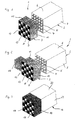
- the molded body 1 shown in Figure 1 consists of a Core body 2 and two connecting bodies 3 forming end bodies, seen in the flow direction for the end areas of the Core body 2 are determined and only one of which is shown here is.
- the core body 2 has a honeycomb structure and accordingly has a plurality of extending in the longitudinal direction Flow channels - designated by way of example with 4 - on.
- the flow channels 4 are through porous intermediate walls - designated by way of example with 5 - separated.
- the outer walls 6, 7 are also porous.
- the connector body 3 is of the same type as the core body 2 built up and forms after connection of the two bodies 2, 3 a continuation of the core body 2. It also has flow channels - exemplified with 8 - on which lie coaxially to the flow channels 4 in the core body 2. However, every second flow channel 8 is by means of a Constipation or covering - labeled 9, for example - closed, so that a checkerboard pattern of closed and open flow channels 8 results.
- the not shown here for the other end of the core body 2 provided connector body is in the same way as end body formed like the connector body 3, but with the difference that the flow channels open at the connector body 3 8 closed and the closed at the connector body 3 Flow channels 8 are open. This will over the connecting body 3 inflowing gas flow forced by to flow through the intermediate walls 5, since it is only in this way the flow channels open at the other connecting body. The flow through the intermediate walls 5 generates the Filter effect of the molded body 1.
- the core body 2 and the connector body 3 consist of a electrically conductive silicon carbide.
- elemental silicon has also been filtered in. The infiltration took place at 1600 ° C under vacuum, the Silicon in platelet form on the outer walls 10, 11, 12, 13 has been applied. Instead of the tiles, too Suspensions, pastes or the like with elemental silicon be applied.
- the connector body 3 after liquefaction of the silicon in to immerse this. Infiltration of the silicon into the Connection body 3 has the result that this one by the factor Obtain 10 to 100 improved electrical conductivity. It also creates a smoother surface. Both favored the soldering of electrodes over which are then electrical Current passed through the connector body 3 and the core body 2 can be.
- the connector body 3 with the Core body 2 connected. This can be done by active soldering. But there is also the possibility of the contact surfaces of core body 2 and connector body 3 with a paste Silicon and carbon powder - possibly still mixed with carbon-containing auxiliaries - and then attach the connector body 3 to the core body 2 and the exposing molded body 1 thus formed to a reaction fire. This creates SiC, which is one in the reaction fire integral connection with the SiC of the connector body 3 and the core body 2 is received and so for a fixed and also provides an electrically conductive connection. For belittling The contact resistance can also be silicon here infiltrated, for example by putting it in the paste is superstoichiometric.
- the exemplary embodiment according to FIG. 2 differs from 1 only in that the connector body 3 one side attached fittings 15, in the silicon is infiltrated in the manner described above and the therefore form contact areas for electrodes.
- FIG. 3 there is a one-piece one Shaped body 16 made of silicon carbide with a length of 30 cm, an edge length of 4 cm and a length resistance of 3 ohms at room temperature.
- the connecting bodies 3 according to Figures 1 and 2 are on the Ends of the molded body 16 every second flow channel - for example designated with 17 7 - by a cover - exemplary designated 18 - closed, so that also here is a checkerboard pattern of open and closed Flow channels 17 forms.
- the one on the side shown open flow channels 17 are closed on the other side, while those provided with the covers 18 Flow channels 17 are open on the other side.
- Both end regions of the molded body 16 are provided with a contact layer 19 provided, which extends over the circumference of the molded body 16 extends.
- the contact layer 19 is partially in the outer walls 20, 21 of the molded body 16 are pressed in.
- Silicon powder is used for the production of the contact layer with a grain size ⁇ 100 ⁇ m and graphite powder with a grain size ⁇ 100 ⁇ m in a weight ratio of 3: 1 mixed Service.
- a carbonaceous binder was placed in one Amount added that the carbon is slightly sub-stoichiometric was present. This powder mixture was made with straight mixed so much water that a cohesive, viscous paste was formed, that on the two ends of the molded body 16 2cm wide was spread. 16 were on each end of the molded body 4g of the paste applied as a thin layer.
- the so obtained Contact coatings were added with 2 to 7g silicon prepared in platelet or powder form.
- the shaped body 16 After drying at 130 ° C., the shaped body 16 became 1600 ° C under vacuum a reaction and infiltration fire subjected. Here the binder was pyrolyzed and reactive Carbon converted. The contact coating reacted to SiC to form contact layer 19 with a much lower porosity than that of the molded body 16. At the same time, the elemental silicon in the contact layer 19 infiltrates, the infiltration in remained essentially limited to the contact layer 19 because it generates higher capillary forces due to its fine porosity than the molded body 16 itself. The contact layer 19 was cohesively connected to the rest of the molded body 16 and has essentially the same properties. Indeed is the electrical conductivity by a factor of 10 to 100 higher than in the molded body 16 itself.
Landscapes
- Chemical & Material Sciences (AREA)
- Engineering & Computer Science (AREA)
- Chemical Kinetics & Catalysis (AREA)
- General Engineering & Computer Science (AREA)
- Combustion & Propulsion (AREA)
- Mechanical Engineering (AREA)
- Ceramic Engineering (AREA)
- Health & Medical Sciences (AREA)
- Toxicology (AREA)
- Structural Engineering (AREA)
- Geometry (AREA)
- Materials Engineering (AREA)
- Physics & Mathematics (AREA)
- Organic Chemistry (AREA)
- Ceramic Products (AREA)
- Manufacture Of Switches (AREA)
- Filtering Materials (AREA)
- Catalysts (AREA)
- Resistance Heating (AREA)
- Exhaust Gas Treatment By Means Of Catalyst (AREA)
- Processes For Solid Components From Exhaust (AREA)
- Separation Using Semi-Permeable Membranes (AREA)
- Filtering Of Dispersed Particles In Gases (AREA)
- Conductive Materials (AREA)
Applications Claiming Priority (2)
| Application Number | Priority Date | Filing Date | Title |
|---|---|---|---|
| DE19809976 | 1998-03-09 | ||
| DE19809976A DE19809976C2 (de) | 1998-03-09 | 1998-03-09 | Formkörper aus einer elektrisch leitfähigen Keramikverbindung sowie Verfahren zur Herstellung des Formkörpers |
Publications (2)
| Publication Number | Publication Date |
|---|---|
| EP0943593A1 EP0943593A1 (de) | 1999-09-22 |
| EP0943593B1 true EP0943593B1 (de) | 2004-01-21 |
Family
ID=7860170
Family Applications (1)
| Application Number | Title | Priority Date | Filing Date |
|---|---|---|---|
| EP99103651A Expired - Lifetime EP0943593B1 (de) | 1998-03-09 | 1999-02-25 | Formkörper aus einer elektrisch leitfähigen Keramik sowie Verfahren zur Herstellung von Kontaktbereichen an solchen Formkörpern |
Country Status (12)
| Country | Link |
|---|---|
| US (1) | US6607804B1 (da) |
| EP (1) | EP0943593B1 (da) |
| JP (1) | JP3149021B2 (da) |
| KR (1) | KR100368677B1 (da) |
| AT (1) | ATE258152T1 (da) |
| BR (1) | BR9902007B1 (da) |
| CA (1) | CA2264422C (da) |
| DE (2) | DE19809976C2 (da) |
| DK (1) | DK0943593T3 (da) |
| ES (1) | ES2213303T3 (da) |
| PT (1) | PT943593E (da) |
| SG (1) | SG71196A1 (da) |
Families Citing this family (18)
| Publication number | Priority date | Publication date | Assignee | Title |
|---|---|---|---|---|
| DE20016803U1 (de) | 2000-09-29 | 2000-12-28 | Thomas Josef Heimbach GmbH, 52353 Düren | Filtereinrichtung |
| DE20100882U1 (de) | 2001-01-18 | 2002-05-23 | Thomas Josef Heimbach GmbH, 52353 Düren | Filtereinrichtung, insbesondere als Rußfilter für Dieselmotorabgase |
| US7090714B2 (en) | 2002-06-17 | 2006-08-15 | Hitachi Metals, Ltd. | Ceramic honeycomb filter |
| CN100393386C (zh) * | 2003-07-14 | 2008-06-11 | 日立金属株式会社 | 陶瓷蜂窝过滤器及其制造方法 |
| EP1801498A1 (en) * | 2005-12-23 | 2007-06-27 | Nederlandse Organisatie voor Toegepast-Natuuurwetenschappelijk Onderzoek TNO | Method for generating radiation |
| DE102006007552B4 (de) * | 2006-02-16 | 2011-02-17 | Peter Sindlhauser | Verfahren zum Beschichten von Körpern aus Graphit oder kohlenstofffaserverstärktem Kohlenstoff und Körper aus Graphit oder kohlenstofffaserverstärktem Kohlenstoff |
| DE102006048832B4 (de) * | 2006-10-11 | 2008-07-24 | Hermsdorfer Institut Für Technische Keramik E.V. | Vorrichtung zum Entfeuchten oder Befeuchten eines Luftstromes |
| DE102006059966A1 (de) * | 2006-12-19 | 2008-06-26 | GM Global Technology Operations, Inc., Detroit | Partikelfilter |
| WO2009107951A2 (ko) * | 2008-02-25 | 2009-09-03 | 제주대학교 산학협력단 | 디젤 엔진의 입자상 물질 저감장치 |
| DE102008041530A1 (de) | 2008-08-25 | 2010-03-04 | Dirk Dombrowski | Verfahren und Abgasanlage zur Reinigung SOx-haltiger Abgase, insbesondere von Schiffsbrennkraftmaschinen |
| JP5791925B2 (ja) * | 2010-04-09 | 2015-10-07 | イビデン株式会社 | ハニカム構造体及び排ガス浄化装置 |
| JP5791918B2 (ja) * | 2010-04-09 | 2015-10-07 | イビデン株式会社 | ハニカム構造体 |
| JP2012106223A (ja) * | 2010-04-09 | 2012-06-07 | Ibiden Co Ltd | ハニカム構造体 |
| JP5612949B2 (ja) * | 2010-07-28 | 2014-10-22 | 東京窯業株式会社 | ハニカム構造体及びフィルタ装置 |
| DE102012109391A1 (de) * | 2012-10-02 | 2014-04-03 | Emitec Gesellschaft Für Emissionstechnologie Mbh | Elektrisch beheizbarer, aus keramischem Material extrudierter Wabenkörper |
| WO2014170907A2 (en) * | 2013-04-17 | 2014-10-23 | Venkata Sundereswar Rao Vempati | An energy efficient pressure less steam generator |
| JP6811196B2 (ja) * | 2018-01-10 | 2021-01-13 | 日本碍子株式会社 | 焼成用セッター |
| WO2024211131A1 (en) * | 2023-04-06 | 2024-10-10 | Corning Incorporated | Manufacturing honeycomb heater body |
Family Cites Families (29)
| Publication number | Priority date | Publication date | Assignee | Title |
|---|---|---|---|---|
| US4017426A (en) * | 1971-12-22 | 1977-04-12 | Groupement Atomique Alsacienne Atlantique | Highly porous conductive ceramics and a method for the preparation of same |
| JPS5148815B2 (da) * | 1973-03-09 | 1976-12-23 | ||
| US4177778A (en) * | 1976-07-29 | 1979-12-11 | Nippondenso Co., Ltd. | Carburetors with heating device |
| DE2905905A1 (de) * | 1978-02-22 | 1979-08-23 | Tdk Electronics Co Ltd | Wabenfoermiges heizelement |
| US4535589A (en) * | 1981-05-26 | 1985-08-20 | Nippon Soken, Inc. | Exhaust gas cleaning device for internal combustion engine |
| US4505107A (en) | 1981-10-26 | 1985-03-19 | Nippondenso Co., Ltd. | Exhaust gas cleaning apparatus |
| JPS61187912A (ja) * | 1985-02-18 | 1986-08-21 | Matsushita Electric Ind Co Ltd | デイ−ゼルパ−テイキユレ−トトラツプ |
| JPS62202868A (ja) * | 1986-02-27 | 1987-09-07 | 電気化学工業株式会社 | 導電性セラミツク及びその製造法 |
| DE3608801A1 (de) | 1986-03-15 | 1987-09-17 | Fev Forsch Energietech Verbr | Verfahren und vorrichtung zur regeneration von partikelfiltersystemen |
| US5017533A (en) * | 1986-09-17 | 1991-05-21 | Lanxide Technology Company, Lp | Method for in situ tailoring the metallic component of ceramic articles |
| DE3704930A1 (de) * | 1987-02-17 | 1988-04-28 | Daimler Benz Ag | Keramisches russabbrennfilter fuer dieselmotoren mit zuendeinrichtung |
| DE3855544T2 (de) * | 1987-04-10 | 1997-03-27 | Hitachi Ltd | Keramische Verbundwerkstoff und Verfahren zur Herstellung desselben |
| US4861641A (en) * | 1987-05-22 | 1989-08-29 | Ceramics Process Systems Corporation | Substrates with dense metal vias |
| DE3729126A1 (de) * | 1987-09-01 | 1989-04-06 | Mototech Motoren Umweltschutz | Dieselruss-partikelfilter und verfahren zu seiner herstellung |
| DE3732654A1 (de) * | 1987-09-28 | 1989-04-13 | Mototech Motoren Umweltschutz | Filter- oder katalysatorelement sowie verfahren zu seiner herstellung |
| US4813231A (en) * | 1987-10-07 | 1989-03-21 | Southwest Research Institute | Engine exhaust after-treatment device |
| DE68928901T2 (de) | 1988-04-08 | 1999-10-14 | Notox A/S | Verfahren zur Herstellung eines porösen Filterkörpers |
| US5526867A (en) * | 1988-11-10 | 1996-06-18 | Lanxide Technology Company, Lp | Methods of forming electronic packages |
| DE4028720A1 (de) * | 1989-09-28 | 1991-04-11 | Interatom | Keramischer wabenkoerper, enthaltend stoffe mit hoher dielektrozitaetskonstante |
| DE4104220C2 (de) * | 1991-02-12 | 1993-10-14 | Specht Klaus Dr | Festkörperkatalysator |
| JPH04342488A (ja) | 1991-05-20 | 1992-11-27 | Isuzu Ceramics Kenkyusho:Kk | 金属とセラミックスの複合体とその製造方法 |
| DE4130630C2 (de) * | 1991-09-14 | 1994-12-08 | Forschungszentrum Juelich Gmbh | Verfahren zur Herstellung poröser, durchströmbarer Formkörper aus Siliciumcarbid und Dieselruß-Filterelement |
| DK205191D0 (da) * | 1991-12-20 | 1991-12-20 | Per Stobbe | Roeggasfilter |
| US5614043A (en) * | 1992-09-17 | 1997-03-25 | Coors Ceramics Company | Method for fabricating electronic components incorporating ceramic-metal composites |
| US5449541A (en) * | 1992-10-27 | 1995-09-12 | Corning Incorporated | Electrically heatable honeycomb structures |
| JPH06173645A (ja) | 1992-12-03 | 1994-06-21 | Isuzu Ceramics Kenkyusho:Kk | 排気ガス処理装置 |
| US5423904A (en) | 1993-05-28 | 1995-06-13 | Dasgupta; Sankar | Exhaust gas filter |
| DE4413127C1 (de) * | 1994-04-19 | 1995-10-05 | Forschungszentrum Juelich Gmbh | Verfahren zur Herstellung poröser, durchströmbarer Formkörper aus Siliciumcarbid und Formkörper |
| ES2180668T3 (es) | 1996-03-23 | 2003-02-16 | Heimbach Gmbh Thomas Josef | Cuerpo moldeado poroso apto para flujo pasante a su traves y procedimiento para su fabricacion. |
-
1998
- 1998-03-09 DE DE19809976A patent/DE19809976C2/de not_active Expired - Fee Related
-
1999
- 1999-02-22 SG SG1999000684A patent/SG71196A1/en unknown
- 1999-02-25 EP EP99103651A patent/EP0943593B1/de not_active Expired - Lifetime
- 1999-02-25 ES ES99103651T patent/ES2213303T3/es not_active Expired - Lifetime
- 1999-02-25 AT AT99103651T patent/ATE258152T1/de not_active IP Right Cessation
- 1999-02-25 DE DE59908333T patent/DE59908333D1/de not_active Expired - Fee Related
- 1999-02-25 DK DK99103651T patent/DK0943593T3/da active
- 1999-02-25 PT PT99103651T patent/PT943593E/pt unknown
- 1999-03-01 US US09/260,147 patent/US6607804B1/en not_active Expired - Fee Related
- 1999-03-05 CA CA002264422A patent/CA2264422C/en not_active Expired - Fee Related
- 1999-03-08 BR BRPI9902007-6A patent/BR9902007B1/pt not_active IP Right Cessation
- 1999-03-08 KR KR10-1999-0007483A patent/KR100368677B1/ko not_active Expired - Fee Related
- 1999-03-09 JP JP06099999A patent/JP3149021B2/ja not_active Expired - Fee Related
Also Published As
| Publication number | Publication date |
|---|---|
| EP0943593A1 (de) | 1999-09-22 |
| BR9902007A (pt) | 2000-09-12 |
| KR19990077673A (ko) | 1999-10-25 |
| KR100368677B1 (ko) | 2003-01-24 |
| DE19809976A1 (de) | 1999-09-16 |
| BR9902007B1 (pt) | 2008-11-18 |
| DE59908333D1 (de) | 2004-02-26 |
| DE19809976C2 (de) | 2001-09-06 |
| DK0943593T3 (da) | 2004-03-29 |
| PT943593E (pt) | 2004-04-30 |
| SG71196A1 (en) | 2000-03-21 |
| CA2264422A1 (en) | 1999-09-09 |
| CA2264422C (en) | 2005-10-04 |
| JP3149021B2 (ja) | 2001-03-26 |
| JPH11324651A (ja) | 1999-11-26 |
| ATE258152T1 (de) | 2004-02-15 |
| US6607804B1 (en) | 2003-08-19 |
| ES2213303T3 (es) | 2004-08-16 |
Similar Documents
| Publication | Publication Date | Title |
|---|---|---|
| EP0943593B1 (de) | Formkörper aus einer elektrisch leitfähigen Keramik sowie Verfahren zur Herstellung von Kontaktbereichen an solchen Formkörpern | |
| EP0796830B1 (de) | Poröser durchströmbarer Formkörper sowie Verfahren zu seiner Herstellung | |
| DE69624884T2 (de) | Wabenkörper | |
| DE4204288C2 (de) | Elektrische Heizvorrichtung | |
| DE68908140T2 (de) | Keramikrohr mit einseitig geschlossenem Rohrmantel und Verfahren zu dessen Herstellung. | |
| DE2333473C3 (de) | Verfahren zur Herstellung eines Kohlenstoffaser-Flächengebildes | |
| DE69720651T2 (de) | Herstellungsverfahren eines keramischen Heizelment | |
| DE19502129C2 (de) | Verfahren zur Herstellung eines elektrisch leitenden Cermets | |
| DE69019552T2 (de) | Verfahren zum Einsetzen eines starren Elements zur Membrantrennung, Filtration oder katalytischen Umwandlung in ein Modul. | |
| DE102017217122B4 (de) | Hochtemperaturbauteil und Verfahren zur Herstellung | |
| DE69906405T2 (de) | Keramischer Heizkörper und Verfahren zum Herstellen desselben | |
| EP1051371B1 (de) | Gesinterter stiftheizer | |
| DE69808908T2 (de) | Keramisches heizelement mit geringer interner spannung | |
| DE3837128C2 (de) | Glühkerze für Dieselmotoren | |
| AT502301B1 (de) | Röntgenanode und verfahren zur herstellung derselben | |
| DE19514643C2 (de) | Verfahren zum Herstellen eines Keramikheizers für Sauerstoffsensoren | |
| EP1452703B1 (de) | Regenerierbares Partikelfilter | |
| DE2907224C2 (de) | Verfahren zur Herstellung eines Verbundkörpers | |
| DE19532158A9 (de) | Sauerstoffkonzentrationsdetektor | |
| DE4413127C1 (de) | Verfahren zur Herstellung poröser, durchströmbarer Formkörper aus Siliciumcarbid und Formkörper | |
| DE3236386A1 (de) | Drehanode fuer roentgenroehren und verfahren zu ihrer herstellung | |
| DE4243864C2 (de) | Verfahren zur Herstellung von Formkörpern aus Siliciumcarbid | |
| DE102020208427A1 (de) | Elektrischer heizträger, abgasreinigungsvorrichtung und herstellungsverfahren für einen elektrischen heizträger | |
| DE2501894A1 (de) | Elektrisches widerstandselement und verfahren zu seiner herstellung | |
| DE2817673A1 (de) | Verfahren und vorrichtung zur herstellung einer auf einem metallischen traeger aufgeschweissten kontaktschicht |
Legal Events
| Date | Code | Title | Description |
|---|---|---|---|
| PUAI | Public reference made under article 153(3) epc to a published international application that has entered the european phase |
Free format text: ORIGINAL CODE: 0009012 |
|
| AK | Designated contracting states |
Kind code of ref document: A1 Designated state(s): AT BE CH DE DK ES FI FR GB GR IT LI LU MC NL PT SE |
|
| AX | Request for extension of the european patent |
Free format text: AL;LT;LV;MK;RO;SI |
|
| 17P | Request for examination filed |
Effective date: 19990923 |
|
| AKX | Designation fees paid |
Free format text: AT BE CH DE DK ES FI FR GB GR IT LI LU MC NL PT SE |
|
| 17Q | First examination report despatched |
Effective date: 20010131 |
|
| GRAH | Despatch of communication of intention to grant a patent |
Free format text: ORIGINAL CODE: EPIDOS IGRA |
|
| GRAS | Grant fee paid |
Free format text: ORIGINAL CODE: EPIDOSNIGR3 |
|
| GRAA | (expected) grant |
Free format text: ORIGINAL CODE: 0009210 |
|
| AK | Designated contracting states |
Kind code of ref document: B1 Designated state(s): AT BE CH DE DK ES FI FR GB GR IT LI LU MC NL PT SE |
|
| REG | Reference to a national code |
Ref country code: GB Ref legal event code: FG4D Free format text: NOT ENGLISH |
|
| REG | Reference to a national code |
Ref country code: CH Ref legal event code: EP |
|
| GRAS | Grant fee paid |
Free format text: ORIGINAL CODE: EPIDOSNIGR3 |
|
| REG | Reference to a national code |
Ref country code: GR Ref legal event code: EP Ref document number: 20040400207 Country of ref document: GR |
|
| REF | Corresponds to: |
Ref document number: 59908333 Country of ref document: DE Date of ref document: 20040226 Kind code of ref document: P |
|
| GBT | Gb: translation of ep patent filed (gb section 77(6)(a)/1977) |
Effective date: 20040223 |
|
| REG | Reference to a national code |
Ref country code: DK Ref legal event code: T3 |
|
| REG | Reference to a national code |
Ref country code: PT Ref legal event code: SC4A Free format text: AVAILABILITY OF NATIONAL TRANSLATION Effective date: 20040303 |
|
| REG | Reference to a national code |
Ref country code: SE Ref legal event code: TRGR |
|
| REG | Reference to a national code |
Ref country code: ES Ref legal event code: FG2A Ref document number: 2213303 Country of ref document: ES Kind code of ref document: T3 |
|
| ET | Fr: translation filed | ||
| PLBE | No opposition filed within time limit |
Free format text: ORIGINAL CODE: 0009261 |
|
| STAA | Information on the status of an ep patent application or granted ep patent |
Free format text: STATUS: NO OPPOSITION FILED WITHIN TIME LIMIT |
|
| 26N | No opposition filed |
Effective date: 20041022 |
|
| PGFP | Annual fee paid to national office [announced via postgrant information from national office to epo] |
Ref country code: ES Payment date: 20080221 Year of fee payment: 10 Ref country code: DK Payment date: 20080226 Year of fee payment: 10 Ref country code: CH Payment date: 20080225 Year of fee payment: 10 |
|
| PGFP | Annual fee paid to national office [announced via postgrant information from national office to epo] |
Ref country code: SE Payment date: 20080225 Year of fee payment: 10 Ref country code: PT Payment date: 20080212 Year of fee payment: 10 Ref country code: NL Payment date: 20080220 Year of fee payment: 10 Ref country code: MC Payment date: 20080220 Year of fee payment: 10 Ref country code: LU Payment date: 20080225 Year of fee payment: 10 Ref country code: IT Payment date: 20080227 Year of fee payment: 10 Ref country code: GB Payment date: 20080222 Year of fee payment: 10 Ref country code: FI Payment date: 20080221 Year of fee payment: 10 Ref country code: DE Payment date: 20071215 Year of fee payment: 10 |
|
| PGFP | Annual fee paid to national office [announced via postgrant information from national office to epo] |
Ref country code: AT Payment date: 20080222 Year of fee payment: 10 |
|
| PGFP | Annual fee paid to national office [announced via postgrant information from national office to epo] |
Ref country code: FR Payment date: 20080219 Year of fee payment: 10 |
|
| PGFP | Annual fee paid to national office [announced via postgrant information from national office to epo] |
Ref country code: BE Payment date: 20080222 Year of fee payment: 10 |
|
| PGFP | Annual fee paid to national office [announced via postgrant information from national office to epo] |
Ref country code: GR Payment date: 20080222 Year of fee payment: 10 |
|
| BERE | Be: lapsed |
Owner name: THOMAS JOSEF *HEIMBACH G.M.B.H. & CO. Effective date: 20090228 |
|
| REG | Reference to a national code |
Ref country code: PT Ref legal event code: MM4A Free format text: LAPSE DUE TO NON-PAYMENT OF FEES Effective date: 20090825 |
|
| PG25 | Lapsed in a contracting state [announced via postgrant information from national office to epo] |
Ref country code: MC Free format text: LAPSE BECAUSE OF NON-PAYMENT OF DUE FEES Effective date: 20090228 |
|
| REG | Reference to a national code |
Ref country code: CH Ref legal event code: PL |
|
| EUG | Se: european patent has lapsed | ||
| REG | Reference to a national code |
Ref country code: DK Ref legal event code: EBP |
|
| GBPC | Gb: european patent ceased through non-payment of renewal fee |
Effective date: 20090225 |
|
| PG25 | Lapsed in a contracting state [announced via postgrant information from national office to epo] |
Ref country code: PT Free format text: LAPSE BECAUSE OF NON-PAYMENT OF DUE FEES Effective date: 20090825 Ref country code: LI Free format text: LAPSE BECAUSE OF NON-PAYMENT OF DUE FEES Effective date: 20090228 Ref country code: FI Free format text: LAPSE BECAUSE OF NON-PAYMENT OF DUE FEES Effective date: 20090225 Ref country code: CH Free format text: LAPSE BECAUSE OF NON-PAYMENT OF DUE FEES Effective date: 20090228 Ref country code: AT Free format text: LAPSE BECAUSE OF NON-PAYMENT OF DUE FEES Effective date: 20090225 |
|
| NLV4 | Nl: lapsed or anulled due to non-payment of the annual fee |
Effective date: 20090901 |
|
| REG | Reference to a national code |
Ref country code: FR Ref legal event code: ST Effective date: 20091030 |
|
| PG25 | Lapsed in a contracting state [announced via postgrant information from national office to epo] |
Ref country code: NL Free format text: LAPSE BECAUSE OF NON-PAYMENT OF DUE FEES Effective date: 20090901 |
|
| PG25 | Lapsed in a contracting state [announced via postgrant information from national office to epo] |
Ref country code: DE Free format text: LAPSE BECAUSE OF NON-PAYMENT OF DUE FEES Effective date: 20090901 |
|
| PG25 | Lapsed in a contracting state [announced via postgrant information from national office to epo] |
Ref country code: BE Free format text: LAPSE BECAUSE OF NON-PAYMENT OF DUE FEES Effective date: 20090228 Ref country code: GR Free format text: LAPSE BECAUSE OF NON-PAYMENT OF DUE FEES Effective date: 20090902 |
|
| REG | Reference to a national code |
Ref country code: ES Ref legal event code: FD2A Effective date: 20090226 |
|
| PG25 | Lapsed in a contracting state [announced via postgrant information from national office to epo] |
Ref country code: GB Free format text: LAPSE BECAUSE OF NON-PAYMENT OF DUE FEES Effective date: 20090225 Ref country code: FR Free format text: LAPSE BECAUSE OF NON-PAYMENT OF DUE FEES Effective date: 20090302 |
|
| PG25 | Lapsed in a contracting state [announced via postgrant information from national office to epo] |
Ref country code: ES Free format text: LAPSE BECAUSE OF NON-PAYMENT OF DUE FEES Effective date: 20090226 Ref country code: DK Free format text: LAPSE BECAUSE OF NON-PAYMENT OF DUE FEES Effective date: 20090831 |
|
| PG25 | Lapsed in a contracting state [announced via postgrant information from national office to epo] |
Ref country code: IT Free format text: LAPSE BECAUSE OF NON-PAYMENT OF DUE FEES Effective date: 20090225 |
|
| PG25 | Lapsed in a contracting state [announced via postgrant information from national office to epo] |
Ref country code: LU Free format text: LAPSE BECAUSE OF NON-PAYMENT OF DUE FEES Effective date: 20090225 |
|
| PG25 | Lapsed in a contracting state [announced via postgrant information from national office to epo] |
Ref country code: SE Free format text: LAPSE BECAUSE OF NON-PAYMENT OF DUE FEES Effective date: 20090226 |