EP0943719A1 - Vorrichtung zum Abdichten von unter Über- oder Unterdruck stehenden Maschinen - Google Patents
Vorrichtung zum Abdichten von unter Über- oder Unterdruck stehenden Maschinen Download PDFInfo
- Publication number
- EP0943719A1 EP0943719A1 EP99104807A EP99104807A EP0943719A1 EP 0943719 A1 EP0943719 A1 EP 0943719A1 EP 99104807 A EP99104807 A EP 99104807A EP 99104807 A EP99104807 A EP 99104807A EP 0943719 A1 EP0943719 A1 EP 0943719A1
- Authority
- EP
- European Patent Office
- Prior art keywords
- flanges
- rollers
- cylinders
- contact
- machine
- Prior art date
- Legal status (The legal status is an assumption and is not a legal conclusion. Google has not performed a legal analysis and makes no representation as to the accuracy of the status listed.)
- Granted
Links
- 238000007789 sealing Methods 0.000 title 1
- 239000004744 fabric Substances 0.000 claims abstract description 15
- 238000012856 packing Methods 0.000 claims description 8
- 229920001971 elastomer Polymers 0.000 claims description 5
- 230000013011 mating Effects 0.000 claims description 3
- 239000013013 elastic material Substances 0.000 claims description 2
- 238000005461 lubrication Methods 0.000 claims description 2
- 239000012809 cooling fluid Substances 0.000 claims 1
- 238000010438 heat treatment Methods 0.000 claims 1
- 239000000463 material Substances 0.000 description 12
- 238000010586 diagram Methods 0.000 description 4
- 229920001343 polytetrafluoroethylene Polymers 0.000 description 4
- 230000000750 progressive effect Effects 0.000 description 4
- 230000009471 action Effects 0.000 description 3
- 230000006835 compression Effects 0.000 description 3
- 238000007906 compression Methods 0.000 description 3
- 238000010276 construction Methods 0.000 description 3
- 230000004323 axial length Effects 0.000 description 2
- 230000008878 coupling Effects 0.000 description 2
- 238000010168 coupling process Methods 0.000 description 2
- 238000005859 coupling reaction Methods 0.000 description 2
- 239000000806 elastomer Substances 0.000 description 2
- 230000005923 long-lasting effect Effects 0.000 description 2
- -1 polytetrafluorethylene Polymers 0.000 description 2
- 238000000926 separation method Methods 0.000 description 2
- 239000004753 textile Substances 0.000 description 2
- 229920000742 Cotton Polymers 0.000 description 1
- 229920001875 Ebonite Polymers 0.000 description 1
- 230000015572 biosynthetic process Effects 0.000 description 1
- 238000004061 bleaching Methods 0.000 description 1
- 230000001419 dependent effect Effects 0.000 description 1
- 238000009990 desizing Methods 0.000 description 1
- 230000018109 developmental process Effects 0.000 description 1
- 230000003628 erosive effect Effects 0.000 description 1
- 239000000675 fabric finishing Substances 0.000 description 1
- 238000009962 finishing (textile) Methods 0.000 description 1
- 239000007788 liquid Substances 0.000 description 1
- 238000012423 maintenance Methods 0.000 description 1
- 239000002184 metal Substances 0.000 description 1
- 238000000034 method Methods 0.000 description 1
- 230000000704 physical effect Effects 0.000 description 1
- 239000002861 polymer material Substances 0.000 description 1
- 230000008569 process Effects 0.000 description 1
- 230000009467 reduction Effects 0.000 description 1
- 229920005989 resin Polymers 0.000 description 1
- 239000011347 resin Substances 0.000 description 1
- 238000009991 scouring Methods 0.000 description 1
- 210000002268 wool Anatomy 0.000 description 1
Images


Classifications
-
- D—TEXTILES; PAPER
- D06—TREATMENT OF TEXTILES OR THE LIKE; LAUNDERING; FLEXIBLE MATERIALS NOT OTHERWISE PROVIDED FOR
- D06B—TREATING TEXTILE MATERIALS USING LIQUIDS, GASES OR VAPOURS
- D06B23/00—Component parts, details, or accessories of apparatus or machines, specially adapted for the treating of textile materials, not restricted to a particular kind of apparatus, provided for in groups D06B1/00 - D06B21/00
- D06B23/14—Containers, e.g. vats
- D06B23/16—Containers, e.g. vats with means for introducing or removing textile materials without modifying container pressure
Definitions
- This invention concerns a device to ensure hold on machines functioning under pressure or depression, as set forth in the main claim.
- the invention concerns a holding device applied both at inlet to and at outlet from machines, apparatus or other equipment defining at least a volume wherein a condition of pressure or depression is created with respect to the ambient pressure.
- the invention is applied preferentially, but not exclusively, to machines or apparatus used in the textile field.
- the devices to ensure that the autoclaves are sealed at inlet and at outlet substantially comprise the same pairs of cylinders which also act as drawing elements for the fabric.
- At least one of the two cylinders is lined with a layer of elastomer so that, since it is subjected to crushing, the contact with the other cylinder does not take place along a line, but over an extended area, thus ensuring the transverse hold, intended in the direction of advance of the fabric.
- the main difficulty of all the systems known to the state of the art is to achieve an efficient lateral hold on the drawing cylinders.
- the state of the art also includes US-A-4,111,434, which, in one of its embodiments, provides holding flanges located in contact with the heads of the drawing cylinders and intermediate rollers, which have a lesser diameter than that of the drawing cylinders, arranged in tangential contact with the drawing cylinders in order to achieve the hold.
- the purpose of the invention is to achieve a holding device to be applied in a machine suitable to work under pressure/depression, which will be configured so as to ensure a holding action both transverse and lateral and extremely efficient under all operating conditions of the machine.
- the holding device is achieved in such a way as to maintain its characteristics substantially unchanged in the course of time, even when there is progressive wear in the parts in reciprocal contact, and even when there are plays and gaps deriving from mechanical stresses and thermal expansion.
- the device according to the invention comprises a pair of rollers made of hard material which are parallel and superimposed, arranged between the drawing cylinder or cylinders and the inlet to the machine.
- rollers are positioned transverse with respect to the direction of advance of the fabric and are in tangential contact against the surface of at least one of the drawing cylinders.
- the rollers have an axial length which is greater than the axial length of the corresponding drawing cylinder.
- the drawing cylinders cooperate, in correspondence with their heads, with plate elements located in contact both with the heads of the cylinders and also with a portion of the lateral surface of the two rollers.
- rollers When they are longer than the drawing cylinders, the rollers protrude laterally from the respective plate elements and are accommodated in suitable seatings made on the plate elements which partly or completely occupy the circumferential development of the rollers.
- the seatings have a suitable thickness and adequate characteristics of mechanical tolerance so as to ensure a reliable and long-lasting hold.
- auxiliary holding elements or pads, between the rollers and the front, fixed part of the machine, which are contained longitudinally between the plate elements so that their ends are always in contact with the plate elements.
- rollers There may be a pad for every roller, or one single pad may be associated with both rollers.
- the length of the auxiliary elements, in a transverse direction to the advance of the fabric can be varied and modified so as to adapt to the specific requirements which occur when the machine is being used under conditions of pressure/depression and to ensure optimum holding conditions always.
- the auxiliary elements allow to compensate and to recover in every operating situation the plays between the parts in reciprocal contact (cylinders, plate elements and rollers) which are created when the machine is working, both due to thermal expansion and also due to the progressive wear which derives from the functioning of the machine and in particular from the reciprocal rubbing of the parts in contact.
- the device ensures a complete hold, both longitudinal and lateral, reliable and long-lasting.
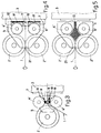
- the fabric 1 is engaged between two drawing cylinders 2' and 2'', advantageously lined with elastomer material, arranged parallel to each other and reciprocally crushed against each other.
- the cylinders 2', 2'' are suitable to insert and extract the fabric 1 into/from an operating machine 3, which is not described in any detail here, and which operates under pressure or depression.
- the holding device denoted in its entirety by the reference number 4 in Fig. 1, is installed between the two cylinders 2', 2'' and the inlet of the fabric 1 into the machine 3.
- the holding device 4 comprises two lateral flanges 5', 5'' arranged in sliding contact with at least part of the heads of the cylinders 2', 2'', two rollers 6', 6'', made of metal, hard resin or other similar hard material, arranged transverse and tangent for the entire length to the surface of the cylinders 2' and 2'', and an intermediate block 7, anchored to the front system of the machine 3.
- the lateral flanges 5' and 5'' are advantageously made of a material which is highly resistant to wear and the applied loads, and with a low friction coefficient.
- the materials used for preference are polymer materials with a PTFE (polytetrafluorethylene) base, for example Valflon® or similar materials.
- the intermediate block 7 has an aperture 20 in a substantially central position, which allows the fabric 1 to enter the machine 3.
- the two lateral flanges 5' and 5'' are maintained in constant elastic thrust against the heads of the cylinders 2' and 2'' due to the action of adjustable elastic elements 8, of a known type.
- the contact surface between the cylinders 2' and 2'' and the flanges 5' and 5'' is defined, in this case, by raised edges 9', 9'', advantageously consisting of rings made of hard rubber or other material with the same mechanical/physical properties, made on or protruding from the lateral walls of the respective cylinders 2', 2''.
- the two rollers 6', 6'' are longer than the corresponding cylinders 2', 2'', with which they are in reciprocal tangential contact on the length, and protrude laterally from the flanges 5' and 5'' thanks to appropriate holes or seatings made at a suitable position thereon.
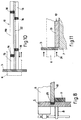
- the pads 10 are positioned in longitudinal sliding contact with the surface of the rollers 6' and 6'' and are housed inside suitable shaped seatings made on the intermediate body 7 (Fig. 9).
- the upper surface of the pads 10 is curved, specifically concave, so as to adhere perfectly with at least part of the surface of the rollers 6' and 6''.
- the pads 10 are made of a material with high characteristics of resistance to wear and the loads applied, and a low friction coefficient, for example Valflon® or similar material.
- the pads 10 are held in lateral contact with the relative flanges 5 and are suitable to modify their length according to the elastic stresses imparted to them by the thrust of the elastic means 8 which act in constant compression against the flanges 5' and 5'' themselves.
- the pads 10 are able to modify their length so as to ensure constant lateral contact against the flanges 5' and 5'' and therefore a constant hold.
- the pads 10 are made in at least two parts, reciprocally sliding with respect to each other, and, in this case, comprise two lateral parts 13 and a central body 110.
- the lateral parts 13 can be anchored, for example, glued, nailed, screwed or otherwise, to the respective flanges 5' and 5'', and are able to slide lengthwise with respect to the central body 110.
- the reciprocal sliding serves to lengthen or shorten the pad 10 when the flanges 5' and 5'' are respectively distanced or brought near, due to the thrust of the elastic means 8, indicated by the number 24 in Fig. 11, in order to recover the play or gaps which are created when the machine 3 is working.
- the end parts 13 are connected to the central body 110 by means of elastic means 14 which guarantee a constant position and that the elastic thrust to bring the parts reciprocally together is maintained.
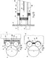
- the reference number 22, in Figs 10 and 13, denotes the zone of sliding contact between the rollers 6' and 6'' and the respective pads 10.
- This area 22 is distributed longitudinally astride the separation zone between the end parts 13 and the central body 110, which ensures that the hold is maintained even when there is the separation zone.
- Fig. 7 provides that the pad 10 is made in a single piece and has elastic packings 14 at the ends suitable to be compressed or dilated so as to allow the pad 10 to shorten or, respectively, lengthen if it is subjected to an elastic stress by the flanges 5' and 5''.
- the elastic packing 14 is arranged in a substantially central position on the length of the pad 10.
- the pad 10 is in a single piece and cooperates, at the ends, with elastic inserts 23 inserted in a mating position in the body of the flanges 5' and 5''.
- the inclusion of the elastic inserts 23 allows the ends of the pad 10 to penetrate inside the body of the flange 5 when the said flange is thrust inwards by the elastic means 8 in order to recover plays or gaps, for example when the edges 9 of the cylinders 2' and 2'' are worn.
- Fig. 3 provides only one cylinder 2 on which the two rollers 6', 6'' are in tangent contact.
- Fig. 4 shows a different conformation of the flange 5, where the area of sliding contact of the flange 5 with the heads of the rollers 6', 6'' extends for the entire circumference thereof.
- the pads 10 are located partly below and partly behind the relative roller 6' and 6'' and surround a substantial part of the arc of the rollers 6' and 6'' facing towards the machine 3.
- the pads 10 inserted into the relative positioning seating made on the intermediate block 7 are supported at the rear by an elastic base 17 which ensures the appropriate compression force against the relative roller 6' and 6''.
- the lateral flanges 5 inside the body of the flanges 5 and in a substantially central position, the lateral flanges 5 include portions 12 made of elastic material, preferably vulcanised rubber, which give a certain elasticity to the body of the flange and thus allow a better sliding adherence of the flanges 5 to the heads of the rollers 6', 6'', even in the case that the rollers 6' and 6'' are partly misaligned.
- Figs. 12 and 13 show a variant of the invention, in diagram form, from the side and from the front, wherein there is only one pad 10 for both the rollers 6' and 6''.
- the pad 10 comprises a central body 110 and two reciprocally sliding lateral parts 13' and 13'' (of which only one is visible); elastic connection elements 14 are interposed between the two parts.
- the two lateral parts 13' and 13'' can be attached to the relative flanges 5.
- the central body 110 of the pad 10 has a central aperture 21 through which the fabric 1 passes.
- the elastic packing 11 does not need to be included.
- the lateral walls of the seating 15 are advantageously lined with rubberised material and at least one wall 16 is movable and/or adjustable so that it is possible to vary the pressure in the zone of reciprocal sliding of the said parts (Fig. 9).
- the hold is ensured by the inclusion of the elastic base 17, preferably made of rubber or consisting of an air chamber with adjustable pressure.
- intermediate block 7 instead of being anchored to the structure of the machine 3, is a single piece therewith.
- the rubberised cylinders and the rollers are supported by means suitable to adjust both their position and also the value of the force of reciprocal compression between the cylinder and roller; these components, either driven or idle, may also be cooled or heated by the circulation of liquid inside.
- the pads 10 and possibly the rollers 6', 6'', PTFE (polytetrafluorethylene) based products are used, or similar products which offer not only a minimum friction coefficient and reasonable elasticity, but also considerable mechanical resistance even at high temperatures, up to 280°C.
Landscapes
- Engineering & Computer Science (AREA)
- Textile Engineering (AREA)
- Treatment Of Fiber Materials (AREA)
- Float Valves (AREA)
- External Artificial Organs (AREA)
- Motor Or Generator Frames (AREA)
- Invalid Beds And Related Equipment (AREA)
Applications Claiming Priority (2)
| Application Number | Priority Date | Filing Date | Title |
|---|---|---|---|
| IT98VI000053A ITVI980053A1 (it) | 1998-03-16 | 1998-03-16 | Dispositivo di tenuta da installare in entrata e/o in uscita su appare cchi funzionanti in regime di pressione o depressione |
| ITVI980053 | 1998-03-16 |
Publications (2)
| Publication Number | Publication Date |
|---|---|
| EP0943719A1 true EP0943719A1 (de) | 1999-09-22 |
| EP0943719B1 EP0943719B1 (de) | 2003-05-21 |
Family
ID=11426632
Family Applications (1)
| Application Number | Title | Priority Date | Filing Date |
|---|---|---|---|
| EP99104807A Expired - Lifetime EP0943719B1 (de) | 1998-03-16 | 1999-03-11 | Vorrichtung zum Abdichten von unter Über- oder Unterdruck stehenden Maschinen |
Country Status (5)
| Country | Link |
|---|---|
| EP (1) | EP0943719B1 (de) |
| AT (1) | ATE241028T1 (de) |
| DE (1) | DE69908003T2 (de) |
| ES (1) | ES2198808T3 (de) |
| IT (1) | ITVI980053A1 (de) |
Cited By (2)
| Publication number | Priority date | Publication date | Assignee | Title |
|---|---|---|---|---|
| EP1762646A3 (de) * | 2005-09-13 | 2008-08-27 | SUPERBA (Société par Actions Simplifiée) | Dichtungsvorrichtung für Maschinen zur Wärmebehandlung von Garnen |
| EP2065501A1 (de) * | 2007-11-29 | 2009-06-03 | LAFER SpA | Maschine zur Behandlung eines Stoffes unter Druck und/oder Unterdruck |
Citations (4)
| Publication number | Priority date | Publication date | Assignee | Title |
|---|---|---|---|---|
| GB1211421A (en) * | 1967-05-11 | 1970-11-04 | Peter Ag Konrad | A sealing device for a web of fabric |
| US3546902A (en) * | 1967-08-28 | 1970-12-15 | Sando Iron Works Co | Pressure sealing device in a continuous high pressure steaming apparatus |
| GB1319352A (en) * | 1970-05-22 | 1973-06-06 | Sando Iron Works Co | Pressure sealing apparatus |
| US4111434A (en) * | 1974-06-10 | 1978-09-05 | Sando Iron Works Co., Ltd. | Method of pressure seal simultaneously employing air-balance of a high pressure steamer and an apparatus therefor |
-
1998
- 1998-03-16 IT IT98VI000053A patent/ITVI980053A1/it unknown
-
1999
- 1999-03-11 AT AT99104807T patent/ATE241028T1/de not_active IP Right Cessation
- 1999-03-11 EP EP99104807A patent/EP0943719B1/de not_active Expired - Lifetime
- 1999-03-11 DE DE69908003T patent/DE69908003T2/de not_active Expired - Fee Related
- 1999-03-11 ES ES99104807T patent/ES2198808T3/es not_active Expired - Lifetime
Patent Citations (4)
| Publication number | Priority date | Publication date | Assignee | Title |
|---|---|---|---|---|
| GB1211421A (en) * | 1967-05-11 | 1970-11-04 | Peter Ag Konrad | A sealing device for a web of fabric |
| US3546902A (en) * | 1967-08-28 | 1970-12-15 | Sando Iron Works Co | Pressure sealing device in a continuous high pressure steaming apparatus |
| GB1319352A (en) * | 1970-05-22 | 1973-06-06 | Sando Iron Works Co | Pressure sealing apparatus |
| US4111434A (en) * | 1974-06-10 | 1978-09-05 | Sando Iron Works Co., Ltd. | Method of pressure seal simultaneously employing air-balance of a high pressure steamer and an apparatus therefor |
Cited By (2)
| Publication number | Priority date | Publication date | Assignee | Title |
|---|---|---|---|---|
| EP1762646A3 (de) * | 2005-09-13 | 2008-08-27 | SUPERBA (Société par Actions Simplifiée) | Dichtungsvorrichtung für Maschinen zur Wärmebehandlung von Garnen |
| EP2065501A1 (de) * | 2007-11-29 | 2009-06-03 | LAFER SpA | Maschine zur Behandlung eines Stoffes unter Druck und/oder Unterdruck |
Also Published As
| Publication number | Publication date |
|---|---|
| ITVI980053A1 (it) | 1999-09-16 |
| DE69908003T2 (de) | 2004-04-01 |
| DE69908003D1 (de) | 2003-06-26 |
| ES2198808T3 (es) | 2004-02-01 |
| ATE241028T1 (de) | 2003-06-15 |
| EP0943719B1 (de) | 2003-05-21 |
Similar Documents
| Publication | Publication Date | Title |
|---|---|---|
| EP0102756B1 (de) | Packung für eine Hochdruck-Plungerpumpe | |
| EP0015144A1 (de) | Kolben und Dichtung für Schlammpumpe | |
| AU2013203809B2 (en) | Roll for a roller grinder, and a roller grinder comprising such a roll | |
| EP0943719B1 (de) | Vorrichtung zum Abdichten von unter Über- oder Unterdruck stehenden Maschinen | |
| EP1033511A2 (de) | Dichtung mit kompressiblem Dichtungsabschnitt und hartem Tragabschnitt | |
| EP0205296A2 (de) | Schmierung von Walzwerken | |
| GB2213767A (en) | Equipment for joining and repairing conveyor belts | |
| JPS62270299A (ja) | 複式ベルトプレス | |
| CA2320434C (en) | Roller grinding mill | |
| EP1335065A2 (de) | Dichtungsanordnung | |
| CZ241196A3 (en) | Device for supporting lateral wall of a two-roll device for continuous casting of metal bands | |
| JP6191935B1 (ja) | ベルトクリーナ | |
| FI963026A0 (fi) | Ruuvipuristimeen tai vastaavaan tarkoitettu kulumiselementti | |
| EP2065501B1 (de) | Maschine zur Behandlung eines Stoffes unter Druck und/oder Unterdruck | |
| CA2261175C (en) | Belt-type particleboard press | |
| CN103009667A (zh) | 连续压机框架组件及连续压机 | |
| US2675258A (en) | Seal ring | |
| US2959433A (en) | Seal | |
| JPH08502792A (ja) | 連続デカタイジングのためのオートクレーブ用織布送入・送出装置 | |
| FI87602C (fi) | Reglerbar taetning | |
| US6829987B2 (en) | Belt-type particleboard press | |
| RU2846699C1 (ru) | Устройство составной тормозной колодки барабанно-колодочного тормоза для транспортных средств | |
| EP1043446A2 (de) | Presswalze | |
| EP0523093B1 (de) | Schneidringklemme für eine tunnelbohrmaschine | |
| SU815388A1 (ru) | Уплотнение манжетного типа |
Legal Events
| Date | Code | Title | Description |
|---|---|---|---|
| PUAI | Public reference made under article 153(3) epc to a published international application that has entered the european phase |
Free format text: ORIGINAL CODE: 0009012 |
|
| AK | Designated contracting states |
Kind code of ref document: A1 Designated state(s): AT BE CH DE DK ES FR GB GR IT LI NL PT |
|
| AX | Request for extension of the european patent |
Free format text: AL;LT;LV;MK;RO;SI |
|
| 17P | Request for examination filed |
Effective date: 20000317 |
|
| AKX | Designation fees paid |
Free format text: AT BE CH DE DK ES FR GB GR IT LI NL PT |
|
| 17Q | First examination report despatched |
Effective date: 20011123 |
|
| GRAG | Despatch of communication of intention to grant |
Free format text: ORIGINAL CODE: EPIDOS AGRA |
|
| GRAG | Despatch of communication of intention to grant |
Free format text: ORIGINAL CODE: EPIDOS AGRA |
|
| GRAH | Despatch of communication of intention to grant a patent |
Free format text: ORIGINAL CODE: EPIDOS IGRA |
|
| GRAH | Despatch of communication of intention to grant a patent |
Free format text: ORIGINAL CODE: EPIDOS IGRA |
|
| GRAA | (expected) grant |
Free format text: ORIGINAL CODE: 0009210 |
|
| AK | Designated contracting states |
Designated state(s): AT BE CH DE DK ES FR GB GR IT LI NL PT |
|
| PG25 | Lapsed in a contracting state [announced via postgrant information from national office to epo] |
Ref country code: NL Free format text: LAPSE BECAUSE OF FAILURE TO SUBMIT A TRANSLATION OF THE DESCRIPTION OR TO PAY THE FEE WITHIN THE PRESCRIBED TIME-LIMIT Effective date: 20030521 |
|
| REG | Reference to a national code |
Ref country code: GB Ref legal event code: FG4D |
|
| REG | Reference to a national code |
Ref country code: CH Ref legal event code: EP |
|
| REF | Corresponds to: |
Ref document number: 69908003 Country of ref document: DE Date of ref document: 20030626 Kind code of ref document: P |
|
| REG | Reference to a national code |
Ref country code: CH Ref legal event code: NV Representative=s name: PATMED AG |
|
| PG25 | Lapsed in a contracting state [announced via postgrant information from national office to epo] |
Ref country code: PT Free format text: LAPSE BECAUSE OF FAILURE TO SUBMIT A TRANSLATION OF THE DESCRIPTION OR TO PAY THE FEE WITHIN THE PRESCRIBED TIME-LIMIT Effective date: 20030821 Ref country code: GR Free format text: LAPSE BECAUSE OF FAILURE TO SUBMIT A TRANSLATION OF THE DESCRIPTION OR TO PAY THE FEE WITHIN THE PRESCRIBED TIME-LIMIT Effective date: 20030821 Ref country code: DK Free format text: LAPSE BECAUSE OF FAILURE TO SUBMIT A TRANSLATION OF THE DESCRIPTION OR TO PAY THE FEE WITHIN THE PRESCRIBED TIME-LIMIT Effective date: 20030821 |
|
| NLV1 | Nl: lapsed or annulled due to failure to fulfill the requirements of art. 29p and 29m of the patents act | ||
| ET | Fr: translation filed | ||
| REG | Reference to a national code |
Ref country code: ES Ref legal event code: FG2A Ref document number: 2198808 Country of ref document: ES Kind code of ref document: T3 |
|
| PLBE | No opposition filed within time limit |
Free format text: ORIGINAL CODE: 0009261 |
|
| STAA | Information on the status of an ep patent application or granted ep patent |
Free format text: STATUS: NO OPPOSITION FILED WITHIN TIME LIMIT |
|
| 26N | No opposition filed |
Effective date: 20040224 |
|
| PG25 | Lapsed in a contracting state [announced via postgrant information from national office to epo] |
Ref country code: IT Free format text: LAPSE BECAUSE OF NON-PAYMENT OF DUE FEES Effective date: 20050311 |
|
| PGFP | Annual fee paid to national office [announced via postgrant information from national office to epo] |
Ref country code: GB Payment date: 20050314 Year of fee payment: 7 |
|
| PGFP | Annual fee paid to national office [announced via postgrant information from national office to epo] |
Ref country code: FR Payment date: 20050315 Year of fee payment: 7 |
|
| PGFP | Annual fee paid to national office [announced via postgrant information from national office to epo] |
Ref country code: ES Payment date: 20050318 Year of fee payment: 7 Ref country code: DE Payment date: 20050318 Year of fee payment: 7 Ref country code: BE Payment date: 20050318 Year of fee payment: 7 Ref country code: AT Payment date: 20050318 Year of fee payment: 7 |
|
| PGFP | Annual fee paid to national office [announced via postgrant information from national office to epo] |
Ref country code: CH Payment date: 20050324 Year of fee payment: 7 |
|
| PG25 | Lapsed in a contracting state [announced via postgrant information from national office to epo] |
Ref country code: GB Free format text: LAPSE BECAUSE OF NON-PAYMENT OF DUE FEES Effective date: 20060311 Ref country code: AT Free format text: LAPSE BECAUSE OF NON-PAYMENT OF DUE FEES Effective date: 20060311 |
|
| PG25 | Lapsed in a contracting state [announced via postgrant information from national office to epo] |
Ref country code: ES Free format text: LAPSE BECAUSE OF NON-PAYMENT OF DUE FEES Effective date: 20060313 |
|
| PG25 | Lapsed in a contracting state [announced via postgrant information from national office to epo] |
Ref country code: LI Free format text: LAPSE BECAUSE OF NON-PAYMENT OF DUE FEES Effective date: 20060331 Ref country code: CH Free format text: LAPSE BECAUSE OF NON-PAYMENT OF DUE FEES Effective date: 20060331 Ref country code: BE Free format text: LAPSE BECAUSE OF NON-PAYMENT OF DUE FEES Effective date: 20060331 |
|
| PG25 | Lapsed in a contracting state [announced via postgrant information from national office to epo] |
Ref country code: DE Free format text: LAPSE BECAUSE OF NON-PAYMENT OF DUE FEES Effective date: 20061003 |
|
| REG | Reference to a national code |
Ref country code: CH Ref legal event code: PL |
|
| GBPC | Gb: european patent ceased through non-payment of renewal fee |
Effective date: 20060311 |
|
| REG | Reference to a national code |
Ref country code: FR Ref legal event code: ST Effective date: 20061130 |
|
| REG | Reference to a national code |
Ref country code: ES Ref legal event code: FD2A Effective date: 20060313 |
|
| BERE | Be: lapsed |
Owner name: *FRANCHETTI ROBERTO Effective date: 20060331 |
|
| PG25 | Lapsed in a contracting state [announced via postgrant information from national office to epo] |
Ref country code: FR Free format text: LAPSE BECAUSE OF NON-PAYMENT OF DUE FEES Effective date: 20060331 |
|
| PGFP | Annual fee paid to national office [announced via postgrant information from national office to epo] |
Ref country code: IT Payment date: 20090323 Year of fee payment: 11 |
|
| PGRI | Patent reinstated in contracting state [announced from national office to epo] |
Ref country code: IT Effective date: 20091201 |
|
| PG25 | Lapsed in a contracting state [announced via postgrant information from national office to epo] |
Ref country code: IT Free format text: LAPSE BECAUSE OF NON-PAYMENT OF DUE FEES Effective date: 20100311 |