EP0943744B1 - Verfahren und Element zur Einleitung von Scherkräften in einen Betonkörper, Betonkörper - Google Patents
Verfahren und Element zur Einleitung von Scherkräften in einen Betonkörper, Betonkörper Download PDFInfo
- Publication number
- EP0943744B1 EP0943744B1 EP98810242A EP98810242A EP0943744B1 EP 0943744 B1 EP0943744 B1 EP 0943744B1 EP 98810242 A EP98810242 A EP 98810242A EP 98810242 A EP98810242 A EP 98810242A EP 0943744 B1 EP0943744 B1 EP 0943744B1
- Authority
- EP
- European Patent Office
- Prior art keywords
- shear force
- concrete
- concrete body
- shear
- forces
- Prior art date
- Legal status (The legal status is an assumption and is not a legal conclusion. Google has not performed a legal analysis and makes no representation as to the accuracy of the status listed.)
- Expired - Lifetime
Links
Images





Classifications
-
- E—FIXED CONSTRUCTIONS
- E04—BUILDING
- E04C—STRUCTURAL ELEMENTS; BUILDING MATERIALS
- E04C5/00—Reinforcing elements, e.g. for concrete; Auxiliary elements therefor
- E04C5/01—Reinforcing elements of metal, e.g. with non-structural coatings
- E04C5/06—Reinforcing elements of metal, e.g. with non-structural coatings of high bending resistance, i.e. of essentially three-dimensional [3D] extent, e.g. lattice girders
- E04C5/0645—Shear reinforcements, e.g. shearheads for floor slabs
-
- E—FIXED CONSTRUCTIONS
- E04—BUILDING
- E04B—GENERAL BUILDING CONSTRUCTIONS; WALLS, e.g. PARTITIONS; ROOFS; FLOORS; CEILINGS; INSULATION OR OTHER PROTECTION OF BUILDINGS
- E04B1/00—Constructions in general; Structures which are not restricted either to walls, e.g. partitions, or floors or ceilings or roofs
- E04B1/02—Structures consisting primarily of load-supporting, block-shaped, or slab-shaped elements
- E04B1/04—Structures consisting primarily of load-supporting, block-shaped, or slab-shaped elements the elements consisting of concrete, e.g. reinforced concrete, or other stone-like material
- E04B1/043—Connections specially adapted therefor
-
- E—FIXED CONSTRUCTIONS
- E04—BUILDING
- E04C—STRUCTURAL ELEMENTS; BUILDING MATERIALS
- E04C5/00—Reinforcing elements, e.g. for concrete; Auxiliary elements therefor
- E04C5/01—Reinforcing elements of metal, e.g. with non-structural coatings
- E04C5/02—Reinforcing elements of metal, e.g. with non-structural coatings of low bending resistance, i.e. of essentially one-dimensional [1D] or two-dimensional [2D] extent
Definitions
- the present invention relates to a method for Introduction of shear forces into a concrete body according to Preamble of claim 1.
- the invention also relates to an element for introduction of shear forces in a concrete body according to the preamble of claim 4.
- the shear force bracket in Figures 1 and 2 is in one Concrete slab 10 shown cast and has one on the Concrete slab face 11 placed steel slab 13 and two with this welded bracket 15, 15 '.
- the plate 13 has an opening 17 in the center into which a mandrel 19 is introduced.
- the two brackets 15, 15 ' are parallel to each other and to the concrete surface away from the plate 13 and are at a distance from the mandrel axis 21 in a parallel Turned towards the mandrel axis 21.
- the end 23 of the Reinforcing steel forming bracket 15, 15 ' is in a relative large distance to the face 11 of the plate by about 165 to 170 Degrees bent and up to about half way against the Front plate back to the end of the mandrel 19.
- the Bracket 15, 15 ' is formed symmetrically to axis 21, see above that shear forces in two opposite directions with the same bracket can be transferred to the concrete slab.
- the four ends 23 of the bracket are with each other and with the mandrel 19
- the bracket 15 shown in Figures 1 and 2 is a two-edged, backward anchored loop with direct centric contact with the bolt, and deviates from those found to be effective in the study mentioned Orders only insofar as those anchored to the rear Reinforcing iron 15, 15 'by means of a plate 13 in a central position Are in contact with the mandrel and the ends 17 are bent and am Thorn are attached.
- a disadvantage of these prefabricated elements is that Compressive forces occur near the concrete surface on the pressure side. There is therefore a risk of blasting off Concrete parts. Another disadvantage is that the resulting Power flow in the concrete remains unclear. The occurring forces are difficult to calculate because the calculations are not easy Model can be used.
- DE-U-90 01 016 is a connection element for Concrete cantilever slabs are known. This has a top chord and a lower chord, which with a truss are connected in a wave-like curved truss.
- the Lower chord has upward ends, which with the End plates enlarging end faces are provided.
- the Truss web is at the bend points on the top chord or bottom flange welded.
- the radii of curvature lie within two separated by insulation Concrete slabs.
- the truss bridge extends between two Points of curvature through the insulation.
- the bracket will thus around a part of the concrete body Concrete core tensioned that in the bracket essentially alone Tractive forces arise.
- the bracket is flat in one Arch stretched around the concrete core. This will kick the Compressive forces in the concrete inside the arch section.
- There the bow section is arranged on the train side is included shear force rod arranged in approximately half the plate thickness certainly a larger part of the plate thickness on the Pressure side than on the tension side of the bracket.
- the flat arch is advantageous stretched symmetrically around the concrete core.
- the symmetry allows a simpler calculation of the forces that occur because the force components directed transversely to the axis of symmetry cancel each other out.
- the sum of the force vectors thus forms a vector on the axis of symmetry.
- the concrete load is in the case of a flat arch section, since only Compressive forces occur in the concrete, similar to a vault.
- a flat arch section has the advantage of smaller ones local pressure forces and a three-dimensional force game, which increases the local resilience of the concrete.
- a first one with the shear force rod is advantageous connected bracket or bracket section around one near the concrete surface and a second with the Shearbar connected bracket or bracket section with opposite direction of action by one concrete core distant from the concrete surface. This can do that due to the eccentric load on the shear force rod occurring moment are caught.
- the bow is ideal for pulling forces in the Arch element in compressive forces in the inside of the arch Transfer core.
- the loop element is so flexible under the forces occurring under load, that it essentially absorbs tensile forces alone. It can e.g. a sheet, a glass or carbon fiber structure or the like. A firm connection with high friction between the Loop element and the concrete is not desirable since the Loop only due to its shape and load Should deliver compressive forces on the encircled concrete core.
- the loop element preferably has one symmetrical arch section, e.g. an arch section with a circular, elliptical or parabolic arc.
- the Forces in such a symmetrical or geometric defined arch section and also by this Forces in the arch caused by concrete are simple Models can be calculated.
- the loop element has in the area of Arch section on a curved surface element, so that the Local forces are as small as possible.
- the loop element is from a band shaped, which has a large width relative to the thickness having.
- a band can be practical in the band direction do not absorb any compressive forces because it is too thin for this.
- the Overall cross section leaves adequate tensile forces in the belt closed, so that high on a concrete core spanned by the belt Pressures can be transferred. Due to the flexibility of the Band can be assumed for the calculation that the band is stretched around a virtual role, so no one-sided pull on the belt is possible. Hence the Pressure distribution in the concrete core within the loop very much simple.
- the arc section is essentially advantageous around an axis is parallel to the concrete surface, and is at least one of those connected to the shear bar Sections of the loop element bent or so twisted that the bent or twisted part along a line or area parallel to the shear force axis Shear bar touches. Due to the parallelism of the arc axis the force distribution is parallel to the concrete surface to the concrete face. As a result, the pressure forces do not show against the concrete surface, which such compressive forces practically cannot record. Through the lines or surface contact between the shear bar and Loop element is a very good attachment option given.
- Holes or eyelets are arranged to attach the shear force element fasten a concrete formwork with nails through the holes can.
- the section of the Bands advantageous at one point away from the concrete surface Section at the appropriate point and are at this protruding location holes in the band provided to the band to fasten a formwork through the holes.
- the loop element is advantageously symmetrical formed with respect to the shear force axis, so that Shear forces in two opposite directions can be introduced into the concrete. This will put the item on the construction site with greater certainty added.
- the shear force rod advantageously has one in the concrete area that is about twice as long is like the distance between the two attachment points of the loop element on the shear force rod, possibly the two fastening points closer to the concrete surface, so practical for the loop element at both fastening points the same burden can be assumed.
- the parallel to the shear force axis is advantageous lying diameter of the arc section smaller than that Distance of the most distant point of the arch section from The shear force rod. This gives you the greatest pressure on the tension side of the shear force rod and therefore with relative large distance to the concrete surface on the pressure side.
- a concrete body with an inventive Shear force element is advantageous in the area around the Shear force elements (40) reinforced by a fiber reinforcement. Due to the fiber reinforcement, both the tension and the Compressive strength of the concrete can be increased.
- the concrete body is advantageously a prefabricated one Element, and reinforcements protrude from the element with which the element with a concrete body cast on site can connect.
- a Prefabricated element can be treated separately Edge area of a concrete body when pouring the concrete body be avoided. As a result, no one is needed on the construction site Monitoring the fiber addition in the concrete with which the Shear force elements are cast.
- the prefabrication allows a rational production of the edge elements under guaranteed conditions for their quality.
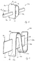
- FIGS 1 to 3 show the prior art, which is described in more detail at the beginning. From Figure 4 onwards Illustrated embodiments of the invention, which for better understanding of the invention in more detail below to be discribed.
- FIG. 4 shows a shear force element 40a with a Shear force mandrel 41a with a rectangular cross-section, on which a bent sheet metal strip 43a is attached as a shear force bracket is.
- the sheet metal strip 43a has one on the end face placing and attached to the mandrel 41a Leg section 45a.
- the leg section 45a goes over in a curved arc section 47a, and this in a leg section parallel to the leg section 45a 49a.
- This section 49a removed from the concrete face of the sheet metal strip 43a is connected to the mandrel 41a.
- the Sheet metal strip 43a is thus with the leg section 45a Concrete surface and with the leg portion 49a inside of the concrete connected to the mandrel 41a.
- the mandrel 41a protrudes the section 45a to be placed in the concrete surface out to absorb or release a lateral force, and extends far behind section 49a into the concrete area into it.
- At the leg portion 49a there are two corners of the band 43a cut off and in the leg section 45a in the corresponding corners holes 51 provided to the Shear force element 40a through these holes 51 on a formwork to be able to fix.
- In the arc section 47a of the band 43a holes 52 are also provided so that under the arch section no air bubbles are left, which is a good one Power transmission between the arc section 47a and would prevent concrete.
- FIG. 5 shows a Shear force element 40b with such a double loop 43b on a shear plate 41b.
- the shear plate 41b penetrates the three leg sections 45b, 49b and 55b. Between the leg sections 45b and 49b or 49b and 55b arc sections 47b and 57b are provided. About these Arch sections 47b, 57b are again alone according to the invention with tensile forces in the loop element 43b compressive forces on the Concrete exercised.
- the leg section 49b is slightly inclined, i.e.
- the shear force mandrel is designed as a disk 41b the advantage that the mandrel 41b in the loading direction 53 is very resilient, and that the loop element 43b over long, resilient weld seams 59 with mandrel 41b is connectable.
- the double loop 43b is also, as in FIG. 6 shown, from two independent loops 43c, 43c ' assemble.
- a sleeve 42c by two oppositely aligned shear bars or loops 43c, 43c 'passed into which sleeve 42c Shear force mandrel is insertable.
- the Shear force elements 40d and 40d ' for example, in two Poured concrete slabs 10 and 10 '.
- the leg sections 45d are the Loop elements 43d directly on both sides of the joint between the two plates 10, 10 'or respectively on the End face 11,11 'of the plate arranged.
- the shear force mandrel 41d bridges the joint and is in the shear sleeve 42d.
- the loop elements 43d are symmetrical in the example trained, i.e. they can be in two to each other opposite directions absorb shear forces as they one on both sides of the mandrel 41d or the sleeve 42d Have arc section 47d or 48d. Is from the plate 10 a shear force down onto the supported plate 10 ' transferred, the arc sections 47d are used to the To transmit force, for forces in the opposite direction the arc sections 48d accordingly.
- the symmetrical Loops 43d are bent from a band so that the mandrel 41d or the sleeve 42d through the two band ends 61 and 63 is guided and they are in contact with each other and at most are additionally connected by welding or gluing. Pressure forces can be in the loop element 43d because of its band-like design practically no occur. On Blowing off concrete parts near the pressure side Concrete surfaces are therefore not to be feared.
- FIG. 8 shows the shear force element 40d according to FIG. 7 in connection with reinforcement of the slab edge a concrete slab corner.
- the section close to the concrete surface 45d of the loop element 43d is in the end face 11 or arranged at a small distance behind the end face 11, the shear force mandrel 41d perpendicular through the end face 11 passes through.
- the plate edge is with U-shaped brackets 64 armored, their arms 66 near the top and bottom Plate surface aligned perpendicular to the face 11 are.
- the connection 68 of the two arms 66 or legs runs parallel to the direction of the face 11 force to be introduced 53.
- the panel edge with fiber reinforcement is preferred, i.e. by adding glass or carbon fibers to the concrete mass, strengthened. Plate pieces reinforced in this way, as in the figure 19 shown, advantageously prefabricated and by a suitable reinforcement connected to the concrete slab.
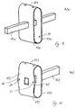
- Figures 9 and 10 show symmetrical loop element 43e and 43f, which are formed by a flattened piece of pipe are.
- the shear force element 40e in Figure 9 is in the Shear force element 40f insertable in Figure 10.
- the thorn 41e works with the sleeve 42f.
- the Loop elements 43e, f have holes 51 around them Nail shear force elements to formwork.
- the Arc sections 47e, 48e, 47f, 48f are holes 52 incorporated so that the interior inside the loop 43e, f is completely filled with concrete when concreting in and no air bubbles have to be transmitted to the pressure forces Included inside the arc sections 47e, f, 48e, f become.
- the holes 51 for attaching the element to the Formwork are advantageous on a laterally protruding Tab 65 formed on leg portion 45f to make it good are accessible.
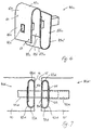
- FIG 11 is a symmetrical shear force element 40g shown with two symmetrical loop elements 43g and 43g 'in a row.
- the sleeve 42g is through all Leg sections 45g, 49g, 49g ', 55g passed through.
- the Leg section 45g is reinforced by a plate 67.
- This plate 67 is located in the end face 11 of a concrete slab 10. Through the plate 67 are also through the arch of the Arch sections 47g, 48g conditionally ending to zero Concrete burrs 69 between the concrete surface 11 and the Protected arc section 47g, 48g. Take over these ridges 69 however not a static function, they are also likely to break out or do not have to be concreted at all.
- loop 43g ' Since in Loop element 43g 'remote from the end face the smaller forces act as a loop element 43g close to the end face, the loop 43g 'is made from a thinner sheet metal strip.
- the concreted-in end of the sleeve 42g has a cover 71 closed so that no concrete can penetrate.
- a symmetrical double loop can, as in FIG. 12 shown to be made from a single band.
- the adjoining leg section 49h 'runs behind the Band end 61 passes through, again in an arc section 58h over in the rear leg section 55h and from there in another bow 57h back in the middle with the Leg sections 49h, 49h '.
- the sleeve 42h therefore passes five times the ribbon guided in a figure of eight.
- FIGS. 13 and 14 show a shear force element 40i in a side view or a section along the line X-X shown in Figure 13.
- Disc-shaped on both sides Shear force mandrel 41i is a band bent into an eight arranged.
- the band ends 61,63 are at one in the Plate 67 to be placed on the concrete surface. from one end of the tape parallel to the plate 67 going upward 61 the ribbon goes back in an arc 47i to the mandrel 41i. It is twisted so that when passing the mandrel 41i the surface 73 of the band parallel to the side surface 75 of the disc-shaped mandrel 41i runs.
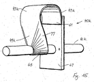
- Figure 15 shows a perspective sketch of a Shear force element 40k with a plate 67, one on it Loop element 43k and a round mandrel 41k. It is one end 61 of the loop member 43k on the plate 67 attached. The other end 63 is divided and the two flanks 77 of the left and right of the mandrel Leg portion 49k are bent obliquely so that they rest on the mandrel on a line parallel to the mandrel axis. The two parts are guided around the mandrel 41k. The Flanks 77 are connected to one another along the mandrel.
- the band-shaped loop element covers with its surface Thorn, which causes greater forces from the thorn to the Loop element can be transferred as if the mandrel just passed through an opening in the surface is.
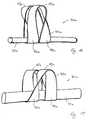
- the loop elements 43m and 43n in the shear force elements 40m and 40n with the thorns 41m, n connected Figures 16 and 17.
- a closed one Band loop or ring loop 43m, n is around the rod-shaped Thorn 41m, n looped and forms two side by side lying, essentially rectified arc sections 47m or 47n.
- the ring loop 43m, n can be against each other ( Figure 16) or apart ( Figure 17).
- Such Fixings of shear force elements 40m, n are also for Loop elements 43m, n made of non-metallic raw materials suitable. So the tape can be made of a glass or Carbon fibers exist, which are advantageously in a resin are embedded.
- the shear force element 40p shown in FIG. 18 has a mandrel 41p around which a ring loop 43p so is struck that the loop 43p near the concrete surface performed flat against the mandrel 41p under the mandrel 41p is.
- the band of the loop element is on both sides of the mandrel twisted by 90 degrees and in an arc 47p, like a roll with an axis aligned parallel to the face of the plate placed, and returned against the mandrel axis.
- the Band 43p is then around on each side of mandrel 41p two rods directed parallel to the face of the plate looped.
- the tape 43p runs under a bar 81 through which rod 81 is attached to the mandrel under the mandrel is.
- the band 43p is in an S line back up and struck around a rod 83 which abuts over the mandrel 41p this is attached.
- the ring band 43p then runs in parallel down on both sides of the mandrel 41p and back, next to over the mandrel 41p to two below the mandrel 41p to form corresponding arc sections 57p and finally twisted by 90 degrees on the top of the mandrel 41p lying flat around the mandrel.
- the driving around of two rods 81.83 with the tape causes the Tractive forces in the front loop part 47p not on the rear loop part 57p are transmitted.
- Figure 19 shows a prefabricated edge element 10 " a number of shear force elements, of which only the 11 protruding parts of the front surface Shear force mandrels 41 are visible.
- This Reinforcements are partly in the concrete body 10 " poured and become the other part after the element 10 "is offset with the reinforcement in the adjacent Slab connected and poured into in-situ concrete.
Landscapes
- Engineering & Computer Science (AREA)
- Architecture (AREA)
- Civil Engineering (AREA)
- Structural Engineering (AREA)
- Physics & Mathematics (AREA)
- Electromagnetism (AREA)
- Bridges Or Land Bridges (AREA)
- Preparation Of Clay, And Manufacture Of Mixtures Containing Clay Or Cement (AREA)
- On-Site Construction Work That Accompanies The Preparation And Application Of Concrete (AREA)
- Crystals, And After-Treatments Of Crystals (AREA)
- Forms Removed On Construction Sites Or Auxiliary Members Thereof (AREA)
Description
- Fig. 1
- einen Schnitt durch ein dem Stand der Technik entsprechendes Scherkraftelement mit Bügeln aus Bewehrungsstahl,
- Fig. 2
- eine Seitenansicht des Scherkraftelements gemäss Figur 1,
- Fig. 3
- ein dem Stand der Technik entsprechendes Scherkraftelement mit einem Scherkraftbügel aus Flacheisen,
- Fig. 4
- eine perspektivische Skizze eines einfachen Ausführungsbeispiels der Erfindung.
- Fig. 5
- eine perspektivische Skizze eines Scherkraftelements mit einer S-förmigen Doppelschlaufe,
- Fig. 6
- eine perspektivische Skizze eines Scherkraftelements mit einer S-Schlaufe, welche aus zwei gleichen Schlaufenelementen zusammengesetzt ist,
- Fig. 7
- eine Anordnung von zwei symmetrischen Scherkraftelementen in zwei benachbarten Plattenrändern,
- Fig. 8
- eine perspektivische Skizze eines Scherkraftelements mit zugeordneter zusätzlicher Bewehrung,
- Fig. 9
- ein Perspektivskizze eines symmetrischen Scherkraftelements mit Dorn,
- Fig. 10
- eine Perspektivskizze eines zum Scherkraftelement gemäss Figur 9 passenden Scherkraftelements mit Hülse,
- Fig. 11
- ein symmetrisches Scherkraftelement mit einem vorderen und einem hinteren Schlaufenelement,
- Fig. 12
- eine Variante zum Scherkraftelement nah Figur 11, bei welcher die vordere und die hintere Schlaufe aus einem Band gefertigt ist,
- Fig. 13
- ein Scherkraftelement mit zwei symmetrischen Schlaufenelementen, welche in einer Achterlinie geführt sind,
- Fig. 14
- einen Schnitt entlang der Linie X-X durch das Scherkraftelement gemäss Figur 13,
- Fig. 15
- eine Perspektivskizze eines Scherkraftelements mit einer bandförmigen Schlaufe, welche den Dorn flächig umfasst,
- Fig. 16
- eine Perspektivskizze eines Scherkraftelements mit einem um den Dorn geschlungenen Ringband,
- Fig. 17
- eine Perspektivskizze eines Scherkraftelements wie in Figur 16, jedoch mit umgekehrter Verdrehung des Ringbandes,
- Fig. 18
- eine Perspektivskizze eines Scherkraftelements mit aus einem Ringband geformter S-förmiger Doppelschlaufe.
Claims (13)
- Verfahren zur Einleitung von Scherkräften (Pfeil 53) in einen Betonkörper (10,10'), insbesondere über die Stirnseite (11,11') einer Betonplatte, bei welcher die Scherkraft (53) von einem axial ausgedehnten Scherkraftstab (41), z.B. von einem Scherkraftdorn (41) oder einer Hülse (42) um den Scherkraftdorn, aufgenommen wird, von diesem auf einen im Betonkörper angeordneten und mit dem Scherkraftstab (41,42) an wenigstens einerbetonoberflächennahen und einer betonoberflächenfernen Stelle verbundenen Scherkraftbügel (43) vom Scherkraftstab (41,42) abgeleitet und vom Scherkraftbügel (43) auf den Beton (10,10') übertragen wird,
dadurch gekennzeichnet, dass der Scherkraftbügel (43) ein Schlaufenelement ist, das aus einem Band geformt ist, welches relativ zur Dicke eine grosse Breite aufweist, die Scherkräfte als Zugkräfte in die mit dem Scherkraftstab (41,42) verbundenen und mit einem flächigen Bogenabschnitt in einem Bogen miteinander verbundenen Schenkelabschnitte (45,49) des Schlaufenelements (43) geleitet werden, und das Schlaufenelement (43) in einem Bogen um einen einen Teil des Betonkörpers bildenden Betonkern gespannt wird, wobei im Scherkraftbügel (43) im Wesentlichen allein Zugkräfte entstehen. - Verfahren nach Anspruch 1, dadurch gekennzeichnet, dass ein erster mit dem Scherkraftstab (41,42) verbundener Bügel (43c,g) oder Bügelabschnitt (47b,h,i,p) um einen betonoberflächennahen Betonkern und ein zweiter mit dem Scherkraftstab (41,42) verbundener Bügel (43c',43g') oder Bügelabschnitt (57b,h,i,p) mit entgegengesetzter Wirkrichtung um einen betonoberflächenfernen Betonkern gespannt wird.
- Verfahren gemäss einem der Ansprüche 1 oder 2,
dadurch gekennzeichnet, dass die im Betonkern auftretenden Spannungen mit einer Faserarmierung im Beton verteilt werden. - Element (31,40a-p) zur Einleitung von Scherkräften (25,53) in einen Betonkörper (10,10'), insbesondere über die Stirnseite (11,11',11") einer Betonplatte, mit einem axialen Scherkraftstab (19,32,41), z.B. von einem Scherkraftdorn (19,32,41) oder einer Hülse (42) um den Scherkraftdorn, und mit einem wenigstens an einer betonoberflächennahen und einer betonoberflächenfernen Stelle am Scherkraftstab (19,32,41,42) befestigten Scherkraftbügel (15,33/35,43), zur Übertragung von Scherkraft auf den Beton, dadurch gekennzeichnet, dass der Scherkraftbügel ein um einen Betonkern spannbares Schlaufenelement (43) ist, das aus einem Band geformt ist, welches relativ zur Dicke eine grosse Breite aufweist, und dass am Scherkraftstab (41,42) befestigte, sich von den Befestigungsstellen zur Zugseite hin erstreckende Schenkelabschnitte (45,49,55) des Schlaufenelements (43)in einem Abstand zum Scherkraftstab (41,42) in einem Bogenabschnitt (47,48,57,58) übergehend ausgebildet sind, und durch den flächigen Bogenabschnitt (47,48,57,58) in einem Bogen miteinander verbunden sind.
- Element nach Anspruch 4, dadurch gekennzeichnet, dass das Schlaufenelement (43) unter den bei Belastung auftretenden Kräften so flexibel ist, dass es im Wesentlichen allein Zugkräfte aufnimmt.
- Element nach Anspruch 4 oder 5, dadurch gekennzeichnet, dass das Schlaufenelement (43a-p,43g') einen im Wesentlichen symmetrischen Bogenabschnitt (47,48,57,58), z.B. etwa einen Kreis-, Ellipsen- oder Parabelbogenabschnitt, aufweist.
- Element nach einem der Ansprüche 4 bis 6, dadurch gekennzeichnet, dass der Bogenabschnitt (47i-p,48i,57i,p,58i) im Wesentlichen um eine Achse parallel zur Betonoberfläche (11) gebogen ist, und dass wenigsten einer der mit dem Scherkraftstab (41,52) verbundenen Abschnitte (45 m-p,49i-n,55p) des Schlaufenelements derart abgebogen oder verdreht ist, dass der abgebogene oder verdrehte Teil (45 m-p,49i-n,55p) entlang einer Linie parallel zur Scherkraftstabachse den Scherkraftstab (41i-p) berührt.
- Element nach einem der Ansprüche 4 bis 7, dadurch gekennzeichnet, dass die beiden am Scherkraftstab (41,42) befestigten Abschnitte (45a,c,d,g,h,49ac,d,g,h) eines Schlaufenelements praktisch parallel verlaufen.
- Element nach einem der Ansprüche 4 bis 8, dadurch gekennzeichnet, dass das Schlaufenelement symmetrisch bezüglich der Scherkraftstabachse ausgebildet ist, so dass mit dem Scherkraftelement Scherkräfte in zwei zueinander entgegengesetzten Richtungen in den Beton einleitbar sind.
- Element nach einem der Ansprüche 4 bis 9, dadurch gekennzeichnet, dass der Scherkraftstab (41a,b,d,e,ip,42c,d,f,g,h) einen in den Beton hineinreichenden Bereich aufweist, welcher etwa doppelt so lang ist wie der Abstand zwischen den beiden Befestigungsstellen des Schlaufenelements am Scherkraftstab, gegebenenfalls den beiden der Betonoberfläche näheren Befestigungsstellen.
- Element nach einem der Ansprüche 4 bis 10, dadurch gekennzeichnet, dass rückwärtig des betonoberflächennahen Bogenabschnitts (47 bzw. 48) ein Bogenabschnitt (57 bzw. 58) angeordnet ist, welcher in der entgegengesetzten Richtung ausgerichtet ist.
- Element nach einem der Ansprüche 4 bis 11, dadurch gekennzeichnet, dass der parallel zur Scherkraftstabachse liegende Durchmesser des Bogenabschnitts (45 m-p,49in,55p) kleiner ist als der Abstand der entferntesten Stelle des Bogenabschnitts (45 m-p,49i-n,55p) vom Scherkraftstab (41,42).
- Betonkörper (10,10',10") mit einem Element (40) nach einem der Ansprüche 4 bis 12, dadurch gekennzeichnet, dass der Betonkörper ein vorfabriziertes Element (10") ist, welches vorzugsweise mit Faserarmierung verstärkt ist, und dass Bewehrungen (81) aus dem Element vorstehen, mit welchen das Element mit einem vor Ort gegossenen Betonkörper eine Verbindung eingehen kann.
Priority Applications (6)
| Application Number | Priority Date | Filing Date | Title |
|---|---|---|---|
| EP98810242A EP0943744B1 (de) | 1998-03-20 | 1998-03-20 | Verfahren und Element zur Einleitung von Scherkräften in einen Betonkörper, Betonkörper |
| DK98810242T DK0943744T3 (da) | 1998-03-20 | 1998-03-20 | Fremgangsmåde og element til indföring af forskydningskræfter i et betonlegeme og et armeret betonlegeme |
| AT98810242T ATE258631T1 (de) | 1998-03-20 | 1998-03-20 | Verfahren und element zur einleitung von scherkräften in einen betonkörper, betonkörper |
| PT98810242T PT943744E (pt) | 1998-03-20 | 1998-03-20 | Processo e elemento para a introducao de tensoes de corte num corpo de betao e corpo de betao |
| ES98810242T ES2215288T3 (es) | 1998-03-20 | 1998-03-20 | Procedimiento y elemento para la introduccion de fuerzas de cizallado en un cuerpo de hormigon. |
| DE59810671T DE59810671D1 (de) | 1998-03-20 | 1998-03-20 | Verfahren und Element zur Einleitung von Scherkräften in einen Betonkörper, Betonkörper |
Applications Claiming Priority (1)
| Application Number | Priority Date | Filing Date | Title |
|---|---|---|---|
| EP98810242A EP0943744B1 (de) | 1998-03-20 | 1998-03-20 | Verfahren und Element zur Einleitung von Scherkräften in einen Betonkörper, Betonkörper |
Publications (2)
| Publication Number | Publication Date |
|---|---|
| EP0943744A1 EP0943744A1 (de) | 1999-09-22 |
| EP0943744B1 true EP0943744B1 (de) | 2004-01-28 |
Family
ID=8236002
Family Applications (1)
| Application Number | Title | Priority Date | Filing Date |
|---|---|---|---|
| EP98810242A Expired - Lifetime EP0943744B1 (de) | 1998-03-20 | 1998-03-20 | Verfahren und Element zur Einleitung von Scherkräften in einen Betonkörper, Betonkörper |
Country Status (6)
| Country | Link |
|---|---|
| EP (1) | EP0943744B1 (de) |
| AT (1) | ATE258631T1 (de) |
| DE (1) | DE59810671D1 (de) |
| DK (1) | DK0943744T3 (de) |
| ES (1) | ES2215288T3 (de) |
| PT (1) | PT943744E (de) |
Families Citing this family (4)
| Publication number | Priority date | Publication date | Assignee | Title |
|---|---|---|---|---|
| EP0943745B1 (de) * | 1998-03-18 | 2005-05-04 | Giulio Albanese | Vorrichtung zur Verankerung eines Spannstabes in einer bewehrten Betonmasse |
| DE19924418A1 (de) * | 1999-05-27 | 2000-11-30 | Schoeck Bauteile Gmbh | Bauelement zur Schubbewehrung |
| DE102008033585B4 (de) * | 2008-07-17 | 2010-04-29 | Bs Ingenieure Ag | Schubdornverbindung |
| DE102010017046A1 (de) * | 2010-05-21 | 2011-11-24 | Max Frank Gmbh & Co Kg | Vorrichtung zum Verbinden von zwei durch eine Fuge getrennte Bauteile und zur Aufnahme von zwischen den Bauteilen auftretenden Querkräften |
Family Cites Families (6)
| Publication number | Priority date | Publication date | Assignee | Title |
|---|---|---|---|---|
| FR332797A (fr) * | 1902-06-13 | 1903-11-06 | Fritz Pohlmann | Système de poutre en ciment armé |
| FR1323763A (fr) * | 1962-03-03 | 1963-04-12 | Ferraillage pour armature de béton, sa fabrication, ses conditions d'emploi et sa mise en oeuvre | |
| CH478969A (de) * | 1966-05-10 | 1969-09-30 | Heierli Walter Dipl Ing | Verwendung von Stahlbetonbauteilen |
| DE9001016U1 (de) * | 1990-01-30 | 1990-04-26 | M. Meisinger Kg, 8890 Aichach | Anschlußelement für eine Betonkragplatte |
| DK0685613T3 (da) * | 1994-06-03 | 1999-09-06 | Nivo Ag | Indretning til optagelse og overføring af tværkræfter mellem to bygningselementer |
| DE4425037C2 (de) * | 1994-07-15 | 2000-03-16 | Glacier Gmbh | Fahrbahnübergang |
-
1998
- 1998-03-20 ES ES98810242T patent/ES2215288T3/es not_active Expired - Lifetime
- 1998-03-20 AT AT98810242T patent/ATE258631T1/de active
- 1998-03-20 DE DE59810671T patent/DE59810671D1/de not_active Expired - Lifetime
- 1998-03-20 EP EP98810242A patent/EP0943744B1/de not_active Expired - Lifetime
- 1998-03-20 PT PT98810242T patent/PT943744E/pt unknown
- 1998-03-20 DK DK98810242T patent/DK0943744T3/da active
Also Published As
| Publication number | Publication date |
|---|---|
| EP0943744A1 (de) | 1999-09-22 |
| ES2215288T3 (es) | 2004-10-01 |
| DE59810671D1 (de) | 2004-03-04 |
| PT943744E (pt) | 2004-06-30 |
| ATE258631T1 (de) | 2004-02-15 |
| DK0943744T3 (da) | 2004-06-07 |
Similar Documents
| Publication | Publication Date | Title |
|---|---|---|
| DE3001309A1 (de) | Tragsystem fuer baukonstruktionen | |
| DE2164417A1 (de) | Fachwerkträger und Herstellungsverfahren | |
| EP0943744A1 (de) | Verfahren und Element zur Einleitung von Scherkräften in einen Betonkörper, Betonkörper | |
| DE19711627C2 (de) | Gitterträgerausbaurahmen und Aussteifungselemente für einen Gitterträgerausbaurahmen | |
| DE1132701B (de) | Geschweisster Stahltraeger von ?-foermigem Querschnitt mit hohlen Flanschen | |
| AT389621B (de) | Balkenfoermiger ausleger, insbesondere als spruehrahmen fuer pflanzenschutzgeraete | |
| EP0079892B1 (de) | Gitterträger | |
| CH661767A5 (de) | Schalungstraeger. | |
| EP0215148B1 (de) | Verbundmittel für Stahlbeton-Verbundtragwerke | |
| EP0307427B1 (de) | Armierung für betonkonstruktionen | |
| DE3786293T2 (de) | Stahl- und bewehrte Betonkonstruktionen, insbesondere zur Trägerherstellung, insbesondere als Dachbalken benutzbarer Träger oder Träger mit grosser Spannweite. | |
| DE2210739A1 (de) | Gittertraeger | |
| DE3148217A1 (de) | Vorrichtung zum befestigen von laengstraegern an querriegeln | |
| EP3315678B1 (de) | Fertigbauteil zum anschluss einer betonkragplatte an ein bauwerk | |
| DE842115C (de) | Deckentragrost | |
| DE902784C (de) | Balken aus Leichtbeton | |
| AT259210B (de) | Verbundträger | |
| DE1609371A1 (de) | Dach- bzw. Deckenkonstruktion in Form einer gekruemmten bzw.verwundenen Flaeche | |
| DE2329943A1 (de) | Gittertraeger | |
| DE616739C (de) | T-foermiger Deckenbalken mit einer Betondruckplatte und einem senkrechten Eisensteg | |
| AT41521B (de) | Eisenbetonkonstruktion mit gitterförmiger Einlage. | |
| CH675605A5 (de) | ||
| DE202006017048U1 (de) | Einrichtung zum gegenseitigen Verbinden der Längsenden wenigstens zweier im Tunnelbau eingesetzter Gitterträger | |
| AT241769B (de) | Ortsbetonrippendecke | |
| DE1409137C (de) | Spannghedstoß fur lagenweise zwischen Klemmpiatten gehaltene Spanndrahte |
Legal Events
| Date | Code | Title | Description |
|---|---|---|---|
| PUAI | Public reference made under article 153(3) epc to a published international application that has entered the european phase |
Free format text: ORIGINAL CODE: 0009012 |
|
| AK | Designated contracting states |
Kind code of ref document: A1 Designated state(s): AT BE CH DE DK ES FI FR GB IE IT LI NL PT SE |
|
| AX | Request for extension of the european patent |
Free format text: AL;LT;LV;MK;RO;SI |
|
| 17P | Request for examination filed |
Effective date: 19991203 |
|
| AKX | Designation fees paid |
Free format text: AT BE CH DE DK ES FI FR GB IE IT LI NL PT SE |
|
| 17Q | First examination report despatched |
Effective date: 20021007 |
|
| GRAP | Despatch of communication of intention to grant a patent |
Free format text: ORIGINAL CODE: EPIDOSNIGR1 |
|
| GRAS | Grant fee paid |
Free format text: ORIGINAL CODE: EPIDOSNIGR3 |
|
| GRAA | (expected) grant |
Free format text: ORIGINAL CODE: 0009210 |
|
| AK | Designated contracting states |
Kind code of ref document: B1 Designated state(s): AT BE CH DE DK ES FI FR GB IE IT LI NL PT SE |
|
| PG25 | Lapsed in a contracting state [announced via postgrant information from national office to epo] |
Ref country code: FI Free format text: LAPSE BECAUSE OF FAILURE TO SUBMIT A TRANSLATION OF THE DESCRIPTION OR TO PAY THE FEE WITHIN THE PRESCRIBED TIME-LIMIT Effective date: 20040128 |
|
| REG | Reference to a national code |
Ref country code: GB Ref legal event code: FG4D Free format text: NOT ENGLISH |
|
| REG | Reference to a national code |
Ref country code: CH Ref legal event code: EP |
|
| REG | Reference to a national code |
Ref country code: IE Ref legal event code: FG4D Free format text: GERMAN |
|
| REF | Corresponds to: |
Ref document number: 59810671 Country of ref document: DE Date of ref document: 20040304 Kind code of ref document: P |
|
| REG | Reference to a national code |
Ref country code: CH Ref legal event code: NV Representative=s name: RIEDERER HASLER & PARTNER PATENTANWAELTE AG |
|
| REG | Reference to a national code |
Ref country code: SE Ref legal event code: TRGR |
|
| GBT | Gb: translation of ep patent filed (gb section 77(6)(a)/1977) |
Effective date: 20040510 |
|
| REG | Reference to a national code |
Ref country code: DK Ref legal event code: T3 |
|
| REG | Reference to a national code |
Ref country code: PT Ref legal event code: SC4A Free format text: AVAILABILITY OF NATIONAL TRANSLATION Effective date: 20040426 |
|
| REG | Reference to a national code |
Ref country code: ES Ref legal event code: FG2A Ref document number: 2215288 Country of ref document: ES Kind code of ref document: T3 |
|
| ET | Fr: translation filed | ||
| PLBE | No opposition filed within time limit |
Free format text: ORIGINAL CODE: 0009261 |
|
| STAA | Information on the status of an ep patent application or granted ep patent |
Free format text: STATUS: NO OPPOSITION FILED WITHIN TIME LIMIT |
|
| 26N | No opposition filed |
Effective date: 20041029 |
|
| REG | Reference to a national code |
Ref country code: HK Ref legal event code: WD Ref document number: 1024939 Country of ref document: HK |
|
| REG | Reference to a national code |
Ref country code: FR Ref legal event code: PLFP Year of fee payment: 19 |
|
| REG | Reference to a national code |
Ref country code: FR Ref legal event code: PLFP Year of fee payment: 20 |
|
| PGFP | Annual fee paid to national office [announced via postgrant information from national office to epo] |
Ref country code: NL Payment date: 20170321 Year of fee payment: 20 Ref country code: SE Payment date: 20170321 Year of fee payment: 20 Ref country code: DE Payment date: 20170322 Year of fee payment: 20 Ref country code: FR Payment date: 20170322 Year of fee payment: 20 Ref country code: CH Payment date: 20170330 Year of fee payment: 20 |
|
| PGFP | Annual fee paid to national office [announced via postgrant information from national office to epo] |
Ref country code: BE Payment date: 20170321 Year of fee payment: 20 Ref country code: IE Payment date: 20170321 Year of fee payment: 20 Ref country code: GB Payment date: 20170322 Year of fee payment: 20 Ref country code: DK Payment date: 20170321 Year of fee payment: 20 Ref country code: AT Payment date: 20170322 Year of fee payment: 20 Ref country code: PT Payment date: 20170317 Year of fee payment: 20 |
|
| PGFP | Annual fee paid to national office [announced via postgrant information from national office to epo] |
Ref country code: ES Payment date: 20170315 Year of fee payment: 20 |
|
| PGFP | Annual fee paid to national office [announced via postgrant information from national office to epo] |
Ref country code: IT Payment date: 20170323 Year of fee payment: 20 |
|
| REG | Reference to a national code |
Ref country code: DE Ref legal event code: R071 Ref document number: 59810671 Country of ref document: DE |
|
| REG | Reference to a national code |
Ref country code: NL Ref legal event code: MK Effective date: 20180319 |
|
| REG | Reference to a national code |
Ref country code: DK Ref legal event code: EUP Effective date: 20180320 |
|
| REG | Reference to a national code |
Ref country code: CH Ref legal event code: PL |
|
| REG | Reference to a national code |
Ref country code: BE Ref legal event code: MK Effective date: 20180320 |
|
| REG | Reference to a national code |
Ref country code: GB Ref legal event code: PE20 Expiry date: 20180319 |
|
| PG25 | Lapsed in a contracting state [announced via postgrant information from national office to epo] |
Ref country code: GB Free format text: LAPSE BECAUSE OF EXPIRATION OF PROTECTION Effective date: 20180319 |
|
| REG | Reference to a national code |
Ref country code: IE Ref legal event code: MK9A Ref country code: SE Ref legal event code: EUG |
|
| REG | Reference to a national code |
Ref country code: AT Ref legal event code: MK07 Ref document number: 258631 Country of ref document: AT Kind code of ref document: T Effective date: 20180320 |
|
| PG25 | Lapsed in a contracting state [announced via postgrant information from national office to epo] |
Ref country code: PT Free format text: LAPSE BECAUSE OF EXPIRATION OF PROTECTION Effective date: 20180328 |
|
| PG25 | Lapsed in a contracting state [announced via postgrant information from national office to epo] |
Ref country code: IE Free format text: LAPSE BECAUSE OF EXPIRATION OF PROTECTION Effective date: 20180320 |
|
| REG | Reference to a national code |
Ref country code: ES Ref legal event code: FD2A Effective date: 20200721 |
|
| PG25 | Lapsed in a contracting state [announced via postgrant information from national office to epo] |
Ref country code: ES Free format text: LAPSE BECAUSE OF EXPIRATION OF PROTECTION Effective date: 20180321 |