EP0943750A2 - Procédé de pose des unités de carreaux - Google Patents
Procédé de pose des unités de carreaux Download PDFInfo
- Publication number
- EP0943750A2 EP0943750A2 EP99105472A EP99105472A EP0943750A2 EP 0943750 A2 EP0943750 A2 EP 0943750A2 EP 99105472 A EP99105472 A EP 99105472A EP 99105472 A EP99105472 A EP 99105472A EP 0943750 A2 EP0943750 A2 EP 0943750A2
- Authority
- EP
- European Patent Office
- Prior art keywords
- tiles
- tile
- mounting bar
- base
- groove
- Prior art date
- Legal status (The legal status is an assumption and is not a legal conclusion. Google has not performed a legal analysis and makes no representation as to the accuracy of the status listed.)
- Withdrawn
Links
- 238000000034 method Methods 0.000 title claims abstract description 11
- 238000005260 corrosion Methods 0.000 abstract 1
- 230000007797 corrosion Effects 0.000 abstract 1
- 239000000853 adhesive Substances 0.000 description 7
- 230000001070 adhesive effect Effects 0.000 description 7
- 238000010276 construction Methods 0.000 description 3
- 239000004570 mortar (masonry) Substances 0.000 description 2
- 125000006850 spacer group Chemical group 0.000 description 2
- 229910000831 Steel Inorganic materials 0.000 description 1
- 229910052782 aluminium Inorganic materials 0.000 description 1
- XAGFODPZIPBFFR-UHFFFAOYSA-N aluminium Chemical compound [Al] XAGFODPZIPBFFR-UHFFFAOYSA-N 0.000 description 1
- 238000005452 bending Methods 0.000 description 1
- 238000007796 conventional method Methods 0.000 description 1
- 229910052751 metal Inorganic materials 0.000 description 1
- 239000002184 metal Substances 0.000 description 1
- 229910001220 stainless steel Inorganic materials 0.000 description 1
- 239000010935 stainless steel Substances 0.000 description 1
- 239000010959 steel Substances 0.000 description 1
Images


Classifications
-
- E—FIXED CONSTRUCTIONS
- E04—BUILDING
- E04F—FINISHING WORK ON BUILDINGS, e.g. STAIRS, FLOORS
- E04F13/00—Coverings or linings, e.g. for walls or ceilings
- E04F13/07—Coverings or linings, e.g. for walls or ceilings composed of covering or lining elements; Sub-structures therefor; Fastening means therefor
- E04F13/08—Coverings or linings, e.g. for walls or ceilings composed of covering or lining elements; Sub-structures therefor; Fastening means therefor composed of a plurality of similar covering or lining elements
- E04F13/0801—Separate fastening elements
- E04F13/0832—Separate fastening elements without load-supporting elongated furring elements between wall and covering elements
- E04F13/0833—Separate fastening elements without load-supporting elongated furring elements between wall and covering elements not adjustable
- E04F13/0835—Separate fastening elements without load-supporting elongated furring elements between wall and covering elements not adjustable the fastening elements extending into the back side of the covering elements
-
- E—FIXED CONSTRUCTIONS
- E04—BUILDING
- E04F—FINISHING WORK ON BUILDINGS, e.g. STAIRS, FLOORS
- E04F13/00—Coverings or linings, e.g. for walls or ceilings
- E04F13/07—Coverings or linings, e.g. for walls or ceilings composed of covering or lining elements; Sub-structures therefor; Fastening means therefor
- E04F13/08—Coverings or linings, e.g. for walls or ceilings composed of covering or lining elements; Sub-structures therefor; Fastening means therefor composed of a plurality of similar covering or lining elements
- E04F13/14—Coverings or linings, e.g. for walls or ceilings composed of covering or lining elements; Sub-structures therefor; Fastening means therefor composed of a plurality of similar covering or lining elements stone or stone-like materials, e.g. ceramics concrete; of glass or with an outer layer of stone or stone-like materials or glass
- E04F13/147—Coverings or linings, e.g. for walls or ceilings composed of covering or lining elements; Sub-structures therefor; Fastening means therefor composed of a plurality of similar covering or lining elements stone or stone-like materials, e.g. ceramics concrete; of glass or with an outer layer of stone or stone-like materials or glass with an outer layer imitating natural stone, brick work or the like
-
- E—FIXED CONSTRUCTIONS
- E04—BUILDING
- E04F—FINISHING WORK ON BUILDINGS, e.g. STAIRS, FLOORS
- E04F15/00—Flooring
- E04F15/02—Flooring or floor layers composed of a number of similar elements
-
- F—MECHANICAL ENGINEERING; LIGHTING; HEATING; WEAPONS; BLASTING
- F16—ENGINEERING ELEMENTS AND UNITS; GENERAL MEASURES FOR PRODUCING AND MAINTAINING EFFECTIVE FUNCTIONING OF MACHINES OR INSTALLATIONS; THERMAL INSULATION IN GENERAL
- F16B—DEVICES FOR FASTENING OR SECURING CONSTRUCTIONAL ELEMENTS OR MACHINE PARTS TOGETHER, e.g. NAILS, BOLTS, CIRCLIPS, CLAMPS, CLIPS OR WEDGES; JOINTS OR JOINTING
- F16B5/00—Joining sheets or plates, e.g. panels, to one another or to strips or bars parallel to them
- F16B5/0004—Joining sheets, plates or panels in abutting relationship
- F16B5/0032—Joining sheets, plates or panels in abutting relationship by moving the sheets, plates, or panels or the interlocking key parallel to the abutting edge
- F16B5/0052—Joining sheets, plates or panels in abutting relationship by moving the sheets, plates, or panels or the interlocking key parallel to the abutting edge the interlocking key acting as a dovetail-type key
Definitions
- This invention relates to a method of laying tiles on walls and floors of a house and tile units.
- tiled wall structures having mounting plates each provided with a rib having an inverse trapezoidal section and fixed to the surface of a wall base to extend the entire lateral or vertical length thereof.
- Tiles P are attached to each mounting plate by engaging the rib of each mounting plate in an inwardly widening trapezoidal groove formed in the back of each tile.
- tiles are fitted on the mounting plates by inserting the ribs into the grooves of the tiles so that the adhesive fills the space between the bottom end of the rib and the bottom of the groove. Otherwise, a keeping member is pressed into the space between the rib and the groove like a wedge to mechanically secure the tiles.
- the tile joint width is uniform, so that it is impossible to cope with changes in the width of tile joints.
- An object of the present invention is to lessen the tile-setting work at the construction site while eliminating the use of an adhesive.
- a method of setting tiles on a base comprising the steps of inserting a mounting bar into a groove formed in the back of each tile from one end thereof, and securing the mounting bar to the base by screws.
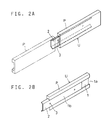
- each tile P has in its back a groove 1 having an inwardly widening trapezoidal section.
- a mounting bar 2 of metal (such as stainless steel, aluminum or steel) is inserted into the groove of one tile from one end la thereof so as not to come out of its opening 1b to form a tile unit U.
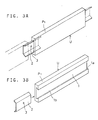
- the bar 2 may be slightly shorter than tiles P as shown in Fig. 2 or much shorter than tiles as shown in Fig. 3.
- the tile unit U With the mounting bar 2 protruding a predetermined length from one end of the groove 1 of the tile, the tile unit U is screwed to a base or wall D by inserting screws through screw holes 3 formed in the mounting bar 2. Then, as shown by chain line in Fig. 2A, another tile P is fitted on the protruding portion of the mounting bar 2 so as to leave a joint of a predetermined width between the tiles.
- a plurality of tiles are mounted on the base D by repeating the above steps. But instead, a plurality of tiles may be joined together by mounting bars in the above manner to form a tile unit U and then the tile unit be screwed to the base D.
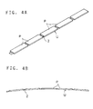
- a plurality of tiles may be joined together by a single mounting bar 2 pierced through the tiles.
- the tiles joined together by such a single long mounting bar can be mounted on a base having an arcuate surface by bending the mounting bar 2 as shown in Fig. 4B.
- the bar 1 may have positioning tabs 4 for positioning tiles.
- the tabs 4 may be portions of the bar 2 formed by cutting and erecting. Such tabs can be erected after tiles P have been fitted on the bar e.g. by use of a screwdriver so that the tabs would not hinder the fitting of tiles on the bar. Joint portions are filled with e.g. mortar.
- a strip of electrical insulating tape T such as paper may be adhered to the backs of the tiles P joined together for positioning of the tiles P.
- the tiles P can thus be easily fixed in position (and thus the joint width between the tiles can be easily adjusted) during mounting of the tiles. Also, since the tiles P do not move relative to the mounting bar 2, the tile unit can be carried easily.
- the number of tiles P and the number of rows of tiles are not limited.
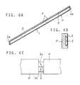
- Each mounting bar 2 may have half-width ends 2a displaced to one and the other sides so that the ends 2a of the adjacent (or integral) mounting bars 2 are disposed one on the other as shown in Fig. 6C. This arrangement makes joint width adjustment easier.
- a plurality of such tiles P arranged in a row may be joined together by a plurality of mounting bars 2 as shown in Figs. 7 and 8.
- a strip of electrical insulating tape may be stuck on the backs of the thus joined tiles.
- the base D may be a wall as in the embodiment or a floor D1 as shown in Fig. 9.
- a gap between the rib of a mounting bar and the groove of a tile may be filled by fitting a spacer 9 and pouring adhesive therearound as shown in Fig. 10.
Landscapes
- Engineering & Computer Science (AREA)
- Architecture (AREA)
- Civil Engineering (AREA)
- Structural Engineering (AREA)
- General Engineering & Computer Science (AREA)
- Mechanical Engineering (AREA)
- Chemical & Material Sciences (AREA)
- Ceramic Engineering (AREA)
- Finishing Walls (AREA)
Applications Claiming Priority (2)
| Application Number | Priority Date | Filing Date | Title |
|---|---|---|---|
| JP6843098A JPH11264228A (ja) | 1998-03-18 | 1998-03-18 | タイル張り工法及びタイルユニット |
| JP6843098 | 1998-03-18 |
Publications (2)
| Publication Number | Publication Date |
|---|---|
| EP0943750A2 true EP0943750A2 (fr) | 1999-09-22 |
| EP0943750A3 EP0943750A3 (fr) | 2000-01-05 |
Family
ID=13373487
Family Applications (1)
| Application Number | Title | Priority Date | Filing Date |
|---|---|---|---|
| EP99105472A Withdrawn EP0943750A3 (fr) | 1998-03-18 | 1999-03-17 | Procédé de pose des unités de carreaux |
Country Status (2)
| Country | Link |
|---|---|
| EP (1) | EP0943750A3 (fr) |
| JP (1) | JPH11264228A (fr) |
Cited By (3)
| Publication number | Priority date | Publication date | Assignee | Title |
|---|---|---|---|---|
| ES2214973A1 (es) * | 2003-03-13 | 2004-09-16 | Ceramicas Garnell S.L | Cenefa con preinstalacion electrica incorporada. |
| EP3179008A1 (fr) * | 2015-12-08 | 2017-06-14 | Krivinka, Zdenek | Système de bardage en briques |
| US20230220677A1 (en) * | 2022-01-10 | 2023-07-13 | John Patrick O'Brien | Decorative quoin installation and illumination system and method |
Families Citing this family (4)
| Publication number | Priority date | Publication date | Assignee | Title |
|---|---|---|---|---|
| JP4678313B2 (ja) * | 2006-02-21 | 2011-04-27 | パナソニック電工株式会社 | サイディング用役物 |
| JP2007284908A (ja) * | 2006-04-13 | 2007-11-01 | Kenji Omiya | 外装下地を用いたブリック壁面及びその施工方法 |
| KR101388165B1 (ko) * | 2012-09-25 | 2014-04-23 | 주식회사 한도스페이스 | 건축물용 외장패널 |
| JP7746098B2 (ja) * | 2021-09-30 | 2025-09-30 | 大和ハウス工業株式会社 | タイル貼り付け情報生成装置およびプログラム |
Citations (5)
| Publication number | Priority date | Publication date | Assignee | Title |
|---|---|---|---|---|
| US1975769A (en) | 1932-06-30 | 1934-10-09 | Cederholm William | Anchor for brick, tile, and the like |
| JPS61282546A (ja) | 1985-06-10 | 1986-12-12 | 元旦ビユーティ工業株式会社 | タイルブロツクを用いた建物の外装壁 |
| JPS6421162A (en) | 1987-07-15 | 1989-01-24 | Funaki Shoji Kk | Tile block wall body and constructing method thereof |
| JPH0681441A (ja) | 1992-09-02 | 1994-03-22 | Rio:Kk | タイルの取付工法 |
| JPH07217155A (ja) | 1994-01-28 | 1995-08-15 | Inax Corp | タイルの施工方法 |
Family Cites Families (3)
| Publication number | Priority date | Publication date | Assignee | Title |
|---|---|---|---|---|
| US4571910A (en) * | 1983-08-01 | 1986-02-25 | Edward Cosentino | Apparatus for laying tile |
| IT219412Z2 (it) * | 1990-03-16 | 1993-02-26 | Dispositivo per il fissaggio di pannelli decorativi su parete o su intelaiatura metallica per la costituzione di facciate ornamentali ventilate | |
| US5417050A (en) * | 1993-03-26 | 1995-05-23 | Cosentino; Edward | Tile mounting system |
-
1998
- 1998-03-18 JP JP6843098A patent/JPH11264228A/ja active Pending
-
1999
- 1999-03-17 EP EP99105472A patent/EP0943750A3/fr not_active Withdrawn
Patent Citations (5)
| Publication number | Priority date | Publication date | Assignee | Title |
|---|---|---|---|---|
| US1975769A (en) | 1932-06-30 | 1934-10-09 | Cederholm William | Anchor for brick, tile, and the like |
| JPS61282546A (ja) | 1985-06-10 | 1986-12-12 | 元旦ビユーティ工業株式会社 | タイルブロツクを用いた建物の外装壁 |
| JPS6421162A (en) | 1987-07-15 | 1989-01-24 | Funaki Shoji Kk | Tile block wall body and constructing method thereof |
| JPH0681441A (ja) | 1992-09-02 | 1994-03-22 | Rio:Kk | タイルの取付工法 |
| JPH07217155A (ja) | 1994-01-28 | 1995-08-15 | Inax Corp | タイルの施工方法 |
Cited By (4)
| Publication number | Priority date | Publication date | Assignee | Title |
|---|---|---|---|---|
| ES2214973A1 (es) * | 2003-03-13 | 2004-09-16 | Ceramicas Garnell S.L | Cenefa con preinstalacion electrica incorporada. |
| EP3179008A1 (fr) * | 2015-12-08 | 2017-06-14 | Krivinka, Zdenek | Système de bardage en briques |
| US20230220677A1 (en) * | 2022-01-10 | 2023-07-13 | John Patrick O'Brien | Decorative quoin installation and illumination system and method |
| US12601182B2 (en) * | 2022-01-10 | 2026-04-14 | John Patrick O'Brien | Decorative quoin installation and illumination system and method |
Also Published As
| Publication number | Publication date |
|---|---|
| JPH11264228A (ja) | 1999-09-28 |
| EP0943750A3 (fr) | 2000-01-05 |
Similar Documents
| Publication | Publication Date | Title |
|---|---|---|
| US5839249A (en) | Foam block wall and fabrication method | |
| US5755070A (en) | Multi veneer anchor structural assembly and drywall construction system | |
| US20040231270A1 (en) | Masonry tie for cavity wall construction | |
| US6237300B1 (en) | Wall stud connectors | |
| US20120073230A1 (en) | Pre-engineered brick panel and methods of making and installing same | |
| EP0575380B1 (fr) | Element support utilise pour le coulage de sols en beton | |
| EP0943750A2 (fr) | Procédé de pose des unités de carreaux | |
| EP1513988A1 (fr) | Systeme d'elements porteurs | |
| EP1075574B1 (fr) | Element de support et procede pour supporter un mur | |
| EP1985774B1 (fr) | Poutre de treillis métallique dans et pour poutres en bois | |
| JP2967816B1 (ja) | バルコニーの構造 | |
| JP3358174B2 (ja) | スラブ構造 | |
| EP1627115A1 (fr) | Unite degradable permettant de former une structure de mur en beton, structure de mur en beton formee au moyen de cette unite, tirant et plaque laterale utilises dans cette unite | |
| JPS6262226B2 (fr) | ||
| US20080271405A1 (en) | Connector Plate and Method of Securing a Building Frame to a Foundation | |
| JP2026019008A (ja) | 壁材固定部材及び壁材の施工方法 | |
| JPH061008B2 (ja) | タイルブロツク壁体およびその構築方法 | |
| JP3201518B2 (ja) | 設備工事用スリーブ支持金具 | |
| JP2718880B2 (ja) | 壁タイル保持構造 | |
| JPH10121717A (ja) | 床板材連結金具 | |
| JPS62141256A (ja) | タイルブロツクの取付構造 | |
| JP4568181B2 (ja) | 間仕切壁の取付方法 | |
| JPH11100978A (ja) | 木製床構造における根太材とフローリング材との結合金具、及び木製フローリング材の敷設方法 | |
| TWM678105U (zh) | 門窗角壁面防裂組件結構及其夾扣 | |
| JP2909700B2 (ja) | タイルの取付装置及び取付工法 |
Legal Events
| Date | Code | Title | Description |
|---|---|---|---|
| PUAI | Public reference made under article 153(3) epc to a published international application that has entered the european phase |
Free format text: ORIGINAL CODE: 0009012 |
|
| AK | Designated contracting states |
Kind code of ref document: A2 Designated state(s): AT BE CH CY DE DK ES FI FR GB GR IE IT LI LU MC NL PT SE |
|
| AX | Request for extension of the european patent |
Free format text: AL;LT;LV;MK;RO;SI |
|
| PUAL | Search report despatched |
Free format text: ORIGINAL CODE: 0009013 |
|
| AK | Designated contracting states |
Kind code of ref document: A3 Designated state(s): AT BE CH CY DE DK ES FI FR GB GR IE IT LI LU MC NL PT SE |
|
| AX | Request for extension of the european patent |
Free format text: AL;LT;LV;MK;RO;SI |
|
| AKX | Designation fees paid | ||
| REG | Reference to a national code |
Ref country code: DE Ref legal event code: 8566 |
|
| STAA | Information on the status of an ep patent application or granted ep patent |
Free format text: STATUS: THE APPLICATION IS DEEMED TO BE WITHDRAWN |
|
| 18D | Application deemed to be withdrawn |
Effective date: 20000706 |