EP0943806B1 - Fluidverdrängungsmaschine - Google Patents
Fluidverdrängungsmaschine Download PDFInfo
- Publication number
- EP0943806B1 EP0943806B1 EP99105334A EP99105334A EP0943806B1 EP 0943806 B1 EP0943806 B1 EP 0943806B1 EP 99105334 A EP99105334 A EP 99105334A EP 99105334 A EP99105334 A EP 99105334A EP 0943806 B1 EP0943806 B1 EP 0943806B1
- Authority
- EP
- European Patent Office
- Prior art keywords
- displacer
- cylinder
- wall face
- fluid machine
- displacement type
- Prior art date
- Legal status (The legal status is an assumption and is not a legal conclusion. Google has not performed a legal analysis and makes no representation as to the accuracy of the status listed.)
- Expired - Lifetime
Links
- 239000012530 fluid Substances 0.000 title claims description 63
- 238000006073 displacement reaction Methods 0.000 title claims description 49
- 238000007906 compression Methods 0.000 claims description 19
- 230000006835 compression Effects 0.000 claims description 17
- 230000002093 peripheral effect Effects 0.000 claims description 15
- 239000000463 material Substances 0.000 claims description 8
- 238000010586 diagram Methods 0.000 description 16
- 230000033001 locomotion Effects 0.000 description 5
- 238000006243 chemical reaction Methods 0.000 description 4
- 238000001816 cooling Methods 0.000 description 4
- 230000000694 effects Effects 0.000 description 4
- 238000000034 method Methods 0.000 description 4
- 238000007664 blowing Methods 0.000 description 3
- 238000003754 machining Methods 0.000 description 3
- 239000003921 oil Substances 0.000 description 3
- XEEYBQQBJWHFJM-UHFFFAOYSA-N Iron Chemical compound [Fe] XEEYBQQBJWHFJM-UHFFFAOYSA-N 0.000 description 2
- 238000004378 air conditioning Methods 0.000 description 2
- 239000002131 composite material Substances 0.000 description 2
- 230000007547 defect Effects 0.000 description 2
- 238000010438 heat treatment Methods 0.000 description 2
- 239000010687 lubricating oil Substances 0.000 description 2
- 230000010349 pulsation Effects 0.000 description 2
- 239000002994 raw material Substances 0.000 description 2
- 239000003507 refrigerant Substances 0.000 description 2
- 235000014676 Phragmites communis Nutrition 0.000 description 1
- 238000004891 communication Methods 0.000 description 1
- 238000010276 construction Methods 0.000 description 1
- 230000003247 decreasing effect Effects 0.000 description 1
- 229910052742 iron Inorganic materials 0.000 description 1
- 238000004519 manufacturing process Methods 0.000 description 1
- 239000002184 metal Substances 0.000 description 1
- 229910052751 metal Inorganic materials 0.000 description 1
- 230000010363 phase shift Effects 0.000 description 1
- 238000005086 pumping Methods 0.000 description 1
- 238000007789 sealing Methods 0.000 description 1
Images


Classifications
-
- F—MECHANICAL ENGINEERING; LIGHTING; HEATING; WEAPONS; BLASTING
- F04—POSITIVE - DISPLACEMENT MACHINES FOR LIQUIDS; PUMPS FOR LIQUIDS OR ELASTIC FLUIDS
- F04C—ROTARY-PISTON, OR OSCILLATING-PISTON, POSITIVE-DISPLACEMENT MACHINES FOR LIQUIDS; ROTARY-PISTON, OR OSCILLATING-PISTON, POSITIVE-DISPLACEMENT PUMPS
- F04C18/00—Rotary-piston pumps specially adapted for elastic fluids
- F04C18/02—Rotary-piston pumps specially adapted for elastic fluids of arcuate-engagement type, i.e. with circular translatory movement of co-operating members, each member having the same number of teeth or tooth-equivalents
- F04C18/04—Rotary-piston pumps specially adapted for elastic fluids of arcuate-engagement type, i.e. with circular translatory movement of co-operating members, each member having the same number of teeth or tooth-equivalents of internal-axis type
-
- F—MECHANICAL ENGINEERING; LIGHTING; HEATING; WEAPONS; BLASTING
- F01—MACHINES OR ENGINES IN GENERAL; ENGINE PLANTS IN GENERAL; STEAM ENGINES
- F01C—ROTARY-PISTON OR OSCILLATING-PISTON MACHINES OR ENGINES
- F01C21/00—Component parts, details or accessories not provided for in groups F01C1/00 - F01C20/00
- F01C21/10—Outer members for co-operation with rotary pistons; Casings
- F01C21/104—Stators; Members defining the outer boundaries of the working chamber
- F01C21/106—Stators; Members defining the outer boundaries of the working chamber with a radial surface, e.g. cam rings
-
- F—MECHANICAL ENGINEERING; LIGHTING; HEATING; WEAPONS; BLASTING
- F04—POSITIVE - DISPLACEMENT MACHINES FOR LIQUIDS; PUMPS FOR LIQUIDS OR ELASTIC FLUIDS
- F04C—ROTARY-PISTON, OR OSCILLATING-PISTON, POSITIVE-DISPLACEMENT MACHINES FOR LIQUIDS; ROTARY-PISTON, OR OSCILLATING-PISTON, POSITIVE-DISPLACEMENT PUMPS
- F04C27/00—Sealing arrangements in rotary-piston pumps specially adapted for elastic fluids
- F04C27/001—Radial sealings for working fluid
-
- F—MECHANICAL ENGINEERING; LIGHTING; HEATING; WEAPONS; BLASTING
- F04—POSITIVE - DISPLACEMENT MACHINES FOR LIQUIDS; PUMPS FOR LIQUIDS OR ELASTIC FLUIDS
- F04C—ROTARY-PISTON, OR OSCILLATING-PISTON, POSITIVE-DISPLACEMENT MACHINES FOR LIQUIDS; ROTARY-PISTON, OR OSCILLATING-PISTON, POSITIVE-DISPLACEMENT PUMPS
- F04C2230/00—Manufacture
- F04C2230/60—Assembly methods
- F04C2230/602—Gap; Clearance
-
- F—MECHANICAL ENGINEERING; LIGHTING; HEATING; WEAPONS; BLASTING
- F04—POSITIVE - DISPLACEMENT MACHINES FOR LIQUIDS; PUMPS FOR LIQUIDS OR ELASTIC FLUIDS
- F04C—ROTARY-PISTON, OR OSCILLATING-PISTON, POSITIVE-DISPLACEMENT MACHINES FOR LIQUIDS; ROTARY-PISTON, OR OSCILLATING-PISTON, POSITIVE-DISPLACEMENT PUMPS
- F04C2240/00—Components
- F04C2240/30—Casings or housings
Definitions
- the present invention relates to a displacement type fluid machine such as a pump, a compressor or expander according to the preamble of claim 1.
- DE 566 296 describes a displacement type fluid machine of the generic kind in which a plurality of spaces is formed between cooperating curved parts of the inner wall surface of a cylinder and the outer wall surface of the displacer, when a positional relationship between the displacer and the cylinder is located at the position of gyration.
- the displacer and the cylinder include cooperating protrusions which come in contact with each other to ensure good sealing of the working spaces towards each other during movement of the displacer.
- a gyration type displacement type fluid machine (as will be abbreviated to the "gyration type fluid machine") has been proposed in Unexamined Japanese Patent Publication No. 55-23353 (Publication 1), U.S.P. No. 2,112,890 (Publication 2), Unexamined Japanese Patent Publication No. 5-202869 (Publication 3) and Unexamined Japanese Patent Publication No. 6-280758 (Publication 4).
- the gyration type fluid machine as disclosed in any of Publications 1 to 4, has essentially advantageous features as the displacement type fluid machine in that it has multiple cylinders and a completely balanced rotating shaft so that it can be lowered in pressure pulsations and vibrations and in the relative sliding rate between a displacer and a cylinder thereby to reduce the frictional loss.
- the stroke of the individual working chambers to be formed by a plurality of vanes composing a displacer and a cylinder from the suction completion to the discharge completion is as short (e.g., about one half of the rotary type and equal to that of the reciprocating type) as about 180 degrees in terms of a shaft rotation angle ⁇ so that the flow velocity in the discharge process is so high as to increase the over compression loss thereby to cause a problem of the reduction in the performance.
- a rotating moment to rotate the displacer itself acts as a reaction from the compressed working fluid upon the displacer so that the moment is received by the contact between the cylinder and the displacer.
- the radial gap is enlarged by the clearance of the shaft drive system for moving the displacer and by the rotating moment acting upon the displacer to increase the internal leakage of the working fluid thereby to cause a problem that the machine performance is lowered.
- the displacer contacts at the outer peripheral portion of its contour with the cylinder so that a seriously excessive load (or the reaction of the contact portion) acts upon the drive shaft because of the small contact angle to raise a problem of the reduction in the reliability such as the seizure of the shaft.
- An object of the invention is to provide a displacement type fluid machine in which one space is formed by the inner wall face of a cylinder and the outer wall face of a displacer when the center of the displacer is located at the center of rotation of a rotating shaft, and in which a plurality of spaces are formed when a positional relationship between the displacer and the cylinder is located at the position of gyration, wherein the load on the drive shaft is lighted while reducing the internal leakage of the working fluid.
- the above-specified object is achieved by providing a displacement type fluid machine in which one space is formed by the inner wall face of a cylinder and the outer wall face of a displacer when the center of said displacer is located at the center of rotation of a rotating shaft, and in which a plurality of spaces are formed when a positional relationship between said displacer and said cylinder is located at the position of gyration, wherein when the center of said displacer is located at the center of rotation of said rotating shaft, the gap between the inner wall face of said cylinder and the outer wall face of said displacer is different depending upon a curvature radius of the outer wall curve of the displacer.
- One embodiment of the aforementioned object is achieved by providing a displacement type fluid machine in which when the center of said displacer is located at the center of rotation of said rotating shaft, the gap between the inner wall face of said cylinder and the outer wall face of said displacer is made alternately wide and narrow.
- Another embodiment of the present invention is achieved by providing a displacement type fluid machine in which one space is formed by the inner wall face of a cylinder and the outer wall face of a displacer when the center of said displacer is located at the center of rotation of a rotating shaft, and in which a plurality of spaces are formed when a positional relationship between said displacer and said cylinder is located at the position of gyration, wherein when the center of said displacer is located at the center of rotation of said rotating shaft, the gap between the inner wall face of said cylinder and the outer wall face of said displacer is made narrow at the portion having a large curvature of the outer wall curve of said displacer.
- the aforementioned object is achieved by providing a displacement type fluid machine in which said displacer is caused by a rotating moment in a fixed direction to slide into contact with said cylinder in a predetermined section, and wherein said cylinder and said displacer are so contoured that the distance in the sliding contact section between the inner wall face of said cylinder and the outer wall face of said displacer is smaller than that of the remaining sections when the center of said displacer is located at the center of rotation of a rotating shaft.
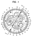
- Fig. 1 is a transverse section of a hermetic type compressor in which a displacement type fluid machine according to one embodiment of the invention is applied to a compressor;
- Fig. 2 is a longitudinal section I - I of Fig. 1;
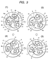
- Fig. 3 presents top plan views showing the working principle of the case in which the displacement type fluid machine of the invention is used as a compressor;
- Figs. 1 is a transverse section of a hermetic type compressor in which a displacement type fluid machine according to one embodiment of the invention is applied to a compressor;
- Fig. 2 is a longitudinal section I - I of Fig. 1;
- Fig. 3 presents top plan views showing the working principle of the case in which the displacement type fluid machine of the invention is used as a compressor;
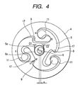
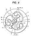
- FIG. 4 to 6 are explanatory diagrams of the gap enlargement in the radial direction between a cylinder and a displacer by the rotating moment acting upon the clearances of the shaft drive system and the displacer;
- Fig. 7 is a top plan view for explaining the contours of the displacer and the cylinder according to the embodiment of the invention; and
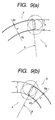
- Fig. 8 presents an enlarged diagram of the portion A of Fig. 7 (in Fig. 8(a)) and an enlarged diagram of the portion B (in Fig. 8(b)).
- reference numeral 1 designates a displacement type compression element according to the invention
- numeral 2 a motor element for driving the former element
- numeral 3 a hermetic casing housing the displacement type compression element 1 and the motor element 2.
- the displacement type compression element 1 is constructed to include: a cylinder 4 having a plurality of protrusions 4b (or also called the “vanes") protruded inward from an inner peripheral wall 4a, and fixing holes 19 for fixing the protrusions 4b; a displacer (or called the “gyrating piston”) arranged inside of the cylinder 4 and meshing with the inner peripheral wall 4a and the protrusions 4b of the cylinder 4; a drive shaft 6 having a crank portion 6a fitted in a bearing 5a at the central portion of the displacer 5 for driving the displacer 5; a main bearing 7 acting, as shown in Fig.
- a cylinder head 8 acting as an end plate for closing the upper end opening of the cylinder 4; a discharge port 9 formed in the end plate of the main bearing 7; a reed valve type discharge valve 10 for opening/closing the discharge port 9, and a stopper (or a valve holder) 10a; and a suction port 11 formed in the cylinder head 8.
- numeral 5b designates oil grooves formed in the two end faces of the displacer 5 and composed of a plurality of shallow grooves (having a depth of about 0.5 mm) curved and extended from the bearing 5a at the central portion to the vicinity of the outer peripheral end, and numeral 5c designates through holes providing communication between the two end faces of the displacer 5.
- numeral 12 designates a suction cover attached to the cylinder head 8 for forming a suction chamber 8a integrally with the cylinder head 8 to define the pressure (or a discharge pressure) in the hermetic casing 3.
- Numeral 13 designates a discharge cover for forming a discharge chamber 7a integrally with the main bearing 7.
- the motor element 2 is composed of a stator 2a and a rotor 2b, of which the rotor 2b is fixed by forcefit or shrinkfit it on one end of the drive shaft 6.
- Numeral 14 designates lubricating oil which is reserved in the bottom portion of the hermetic casing 3 to soak the lower end portion of the drive shaft 6.
- Numeral 6b designates an oil feed hole for feeding the lubricating oil 14 to the individual sliding portions such as the bearings with the centrifugal pumping action by the rotation of the drive shaft 6.
- An oil feed pipe 6c is connected to the shaft end of the drive shaft 6.
- Numeral 15 designates a suction pipe
- numeral 16 designates a discharge pipe.
- numeral 17 designates working chambers which are defined by the engagements between the inner peripheral walls 4a and the protrusions 4b of the cylinder 4 and the displacer 5.
- numeral 18 designates assembling bolts of the compression element
- numeral 19 designates fixing bolts for preventing the protrusions 4b of the cylinder 4 from being deformed by the pressure.
- the flow of the working gas will be described with reference to Fig. 2.
- the working gas thus compressed flows through the discharge port 9 formed in the end plate of the main bearing 7 into the discharge chamber 7a while raising the discharge valve 10 and further flows from the discharge cover 13 through the hermetic casing 3 and the discharge pipe 16 to the outside (while forming the so-called "high-pressure chamber").
- Reference letter o designates the center of the displacer 5.
- Reference letter o' designates the center of the cylinder 4 (or the drive shaft 6).
- Reference letters a, b, c, d, e and f designate engaging points (or seal points) where the inner peripheral wall 4a of the cylinder 4 and the vane 4b engage with the displacer 5.
- engaging points or seal points
- a curve forming the inner peripheral wall 4a and the vane 4b is composed of two curves: one inward convex vortex curve having an angle of substantially 360 degrees; and one inward concave vortex curve having an angle of substantially 360 degrees. These curves are arranged at a substantially equal pitch on a circumference around the center o', the adjoining convex and concave curves are connected through smooth curves such as arcs to form an inner peripheral contour.
- the outer peripheral contour of the displacer 5 is also formed on the same principle as that of the cylinder 4.
- Fig. 3(1) shows a state in which the working gas suction from the suction port 11 to this working chamber is completed.
- FIG. 3(2) shows a state in which the drive shaft 6 (or the crank portion 6a) is rotated clockwise by 90 degrees from the state shown in Fig. 3(1).
- Fig. 3(3) shows a state in which the drive shaft 6 is further rotated by 180 degrees from the state shown in Fig. 3(1).
- the drive shaft 6 shown in Fig. 3(3) is further rotated by 90 degrees, the drive shaft 6 returns to the first state shown in Fig. 3(1).
- the discharge port 9 is closed by the discharge valve 10
- the working fluid is compressed.
- the discharge valve 10 is automatically opened by the pressure difference, so that the compressed working gas is discharged through the discharge port 9.
- the shaft angle from the suction completion (the compression start) to the discharge completion is 360 degrees.
- a next suction process is prepared while each compression and discharge process is being carried out.
- a next compression process is started at the discharge completion.
- the working chambers for these sequential compressions are distributed and arranged at the substantially equal pitch around the drive bearing 5a located at the central portion of the displacer 5.
- the cylinder and the displacer are contoured to form the gap ⁇ of a predetermined width between the cylinder and the displacer when they are aligned to each other.
- the eccentricity of the drive shaft will be considered for the same gap ⁇ .
- Fig. 4 is an explanatory diagram of the clearance of the shaft drive system
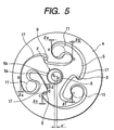
- Fig. 5 is an explanatory diagram of the radial gap due to the clearance of the shaft drive system
- Fig. 6 is an explanatory diagram of the radial gap resulting from the rotating moment acting upon the clearance of the shaft drive system and the displacer.
- the radial gaps of the individual working chambers 17 at the seal points a, b, c, d, e and f are zero.
- the fluid pressure due to the pressure in the working chambers acts upon the displacer so that the radial gap changes, as shown in Figs. 5 and 6.
- Fig. 5 shows the radial gap due to the clearance of the shaft drive system with no consideration into the rotary displacement of the displacer itself.
- a resultant force F in the displacement type fluid machine, in which one space is formed by the inner wall face of the cylinder and the outer wall face of the displacer when the center of rotation of the rotating shaft is located at the center of the displacer, and in which a plurality of working spaces are formed when the positional relation between the displacer and the cylinder are located at a gyrating position
- the resultant force F of the pressures in the individual working chambers never fails to act from the eccentric direction so that it acts to reduce the gyrating radius
- the drive shaft 6 becomes eccentric in the individual bearings so that the gyrating radius of the displacer 5 becomes small tao ⁇ ' ( ⁇ ⁇ ).
- FIG. 5 shows the case in which the angular displacement of the displacer itself is not considered.
- the rotating moment M rotates the displacer 5 by the resultant force F, however, the radial gap changes, as shown in Fig. 6.
- the rotating moment M rotates the displacer 5 (counter-clockwise) opposed to the gyrating direction (or clockwise) by the resultant force F.
- the eccentricity of the drive shaft increases to enlarge the gyrating radius of the displacer.
- the displacer having the small radial gap comes into contact at the seal point a of its outer periphery of the contour with the cylinder. Since this portion has a small contact angle, an excessively high load (or the reaction of the contact portion) acts on the drive shaft to cause a problem of a reduction in the reliability such as the seizure of the shaft.
- Fig. 7 is a top plan view showing the contours of the cylinder and the displacer according to one embodiment of the invention
- Fig. 8 presents an enlarged diagram of the portion A of Fig. 7 (in Fig. 8 (a)) and an enlarged diagram of the portion B (in Fig. 8(b)).
- Fig. 7 overlaps the center o' of the cylinder 4 and the center o of the displacer 5.
- the gap between the cylinder 4 and the displacer 5 (i.e., the normal distance between the two contour curves of the cylinder and the displacer) is not constant but is made alternately wider and narrower.
- the load of the rotating moment on the drive shaft is lighter than at the portion having a larger radius of curvature. In this embodiment, therefore, the rotating moment is received at the portion of the smaller radius of curvature.
- the cylinder and the displacer are so contoured that the distance ⁇ between the cylinder inner wall face and the displacer outer wall face in the section (as indicated by angles ⁇ and ⁇ ) for the sliding contact by the rotating moment of the displacer is made smaller than that ⁇ of the remaining sections.
- the distance ⁇ ' is expressed to satisfy the following relations, for example, when the aforementioned clearance of the shaft drive system is considered and when the ⁇ indicates the shaft eccentricity: ⁇ > ⁇ ' ⁇ ( ⁇ - (C1 + C2 ) )
- the magnitudes of the angles ⁇ and ⁇ of the sliding contact sections are so set to or more than the angle (e.g., 120 degrees because the three working chambers are formed, as shown) of the phase difference of the compression stroke of the individual working chambers that a smooth contact may be realized no matter what position of rotational angle the drive shaft might be located at.
- the sliding contact section of the distance ⁇ ' and the non-sliding contact section of the distance ⁇ are connected through an arc of a radius r, as illustrated in an enlarged scale in Fig. 8.
- the correction ⁇ ⁇ - ⁇ '
- the play in the rotational direction of the displacer itself with the cylinder 4 and the displacer 5 being meshing with each other is so small that the radial gap is not enlarged by the clearance of the shaft drive system and the rotating moment acting on the displacer. Since no contact exists other than the section to be brought into sliding contact by the rotating moment acting upon the displacer, moreover, there does not arise the problem in which the reliability is lowered by the excessive load acting upon the drive shaft. As a result, the radial gap between the cylinder and the displacer can be kept at the optimum value to provide the gyration type fluid machine capable of improving the performance and the reliability.
- the correction ⁇ of the contour is kept at the constant value but could be made variable depending upon the place of the sliding contact section by considering the bearing characteristics.
- the contour is corrected only on the side of the cylinder 4.
- the correction of the contour can be executed for both the cylinder 4 (e.g., a correction ⁇ s) and the displacer 5 (e.g., a correction ⁇ p).
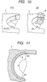
- Fig. 10 shows an embodiment of this machining operation.
- Fig. 10(1) shows the shape of a portion of a raw material (or cylinder).
- the raw material is made of a sintered metal such as iron and is precisely molded and shaped to leave a finishing allowance ⁇ at the sliding contact section (of the angle ⁇ ). As shown in Fig.
- the machining finish with a grinding tool 20 or the like may be limited to that sliding contact section so that the working time period can be drastically shortened, as compared with the case in which the contour is machined all over its periphery, to lower the cost.
- Fig. 11 is an enlarged section of an essential portion of a cylinder according to another embodiment of the invention.
- the cylinder and the displacer are made of the single material in the embodiments thus far described, the invention should not be limited thereto but they could be made of two or more kinds of composite materials.
- numeral 21 designates a wear resisting material which is fitted in the sliding contact section (of the angle ⁇ ) of the cylinder 4, and the contour of the ⁇ s is corrected.
- Fig. 11 presents the cylinder side, but the displacer side can also be likewise constructed.
- this composite structure it is made possible to improve the reliability for the wears of the cylinder and the displacer.
- similar effects could also be achieved by making the material surface of the sliding contact section of the cylinder and the displacer harder of the single material than the remaining section. This structure is also contained in the invention.
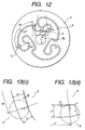
- Fig. 12 is a top plan view showing the contour of the cylinder and the displacer according to still another embodiment of the invention
- Fig. 13 presents an enlarged diagram showing portion C of Fig. 12 (in Fig. 13(c)) and an enlarged diagram showing portion D (in Fig. 13(d)).
- the center o' of the cylinder 4 and the center o of the displacer 5 are overlapped as in Fig. 7.
- Fig. 7 As has also been described with reference to Fig.
- the relations between the distances ⁇ " and ⁇ are made to satisfy the following examples, if the value ⁇ " is the shaft eccentricity while considering the aforementioned clearance of the shaft drive system: ⁇ " > ⁇ ⁇ ( ⁇ " - (C1 + C2))
- the angles ⁇ o and ⁇ i of the contour correcting section are expressed by the apex angle of a single arc, when the contour is the single one, and by the sum of the apex angles of multiple arcs when the contour is composed of the multiple arcs.
- the section of the normal distance ⁇ " and the section of the normal distance ⁇ are connected through an arc of the radius r, as shown in an enlarged scale in Fig. 13.
- the contact problem in the peripheral contour of the cylinder 4 and the displacer 5 can be solved to improve the reliability, and the radial gap can also be reduced to provide a gyration type fluid machine capable of improving the performance.
- the invention has been described in connection with the high-pressure type compressor, it should not be limited thereto but could likewise applied for similar effects to a low-pressure type compressor in which the pressure in the hermetic casing is a suction pressure.
- the invention has been exemplified by the case in which the cylinder 4 and the displacer 5 are contoured to form the three working chambers, on the other hand, it could be expanded to the case in which the number of working chambers is 3 to N (the value of which is practically limited by an upper limit of 8 to 10).
- the contour of the compression element should not be limited to those of the embodiments, but the invention could also be applied to the general gyration type fluid machine which includes: a cylinder having an inner wall composed of continuous curves in its sectional shape; and a displacer having an outer wall facing the inner wall of the cylinder for forming, when gyrated, a plurality of spaces between the inner wall and the outer wall, so that the working fluid is conveyed by the cylinder and the displacer.
- the displacement type fluid machine according to the invention can be applied to a compressor for an air conditioning system, which makes use of a heat pump cycle for the cooling and heating operations.
- a displacement type compressor 30 operates, as illustrated in the operation principle diagram of Fig. 3, so that the working fluid (e.g., refrigerant HCFC22, R407C or R410A) is compressed between the cylinder 4 and the displacer 5 by starting the compressor.
- the working fluid e.g., refrigerant HCFC22, R407C or R410A
- the compressed working gas at a high temperature and under a high pressure flows from the discharge pipe 16 through a four-way valve into an outdoor heat exchanger in which it liberates its heat and is liquefied with the blowing action of the outdoor fan, and is throttled by an expansion valve so that it is adiabatically expanded to a low temperature and a low pressure.
- This expanded working fluid is caused to absorb the heat in the room by an indoor heat exchanger and is gasified and sucked via the suction pipe 15 into the displacement type compressor 30.
- the refrigerant is delivered backward of the cooling operation by switching the four-way valve, and the compressed high-temperature and high-pressure working gas flows from the discharge pipe 16 through the four-way valve into the indoor heat exchanger so that it liberates its heat and is liquefied by the blowing action of the indoor fan.
- the working fluid is then throttled by the expansion valve so that it is adiabatically expanded to a low temperature and a low pressure.
- the expanded working fluid is caused to absorb the heat from the atmosphere by the outdoor heat exchanger and is gasified. After this, the working gas is sucked through the suction pipe 15 into the displacement type compressor 30.
- the displacement type compressor of the invention can also be applied to a cycle especially for the refrigerating (or cooling) operation.
- this cycle by starting the displacement type compressor 30, the working fluid is compressed between the cylinder 4 and the displacer 5, and the compressed high-temperature and high-pressure working gas flows from the discharge pipe 16 to a condenser, in which it liberates its heat and is liquefied by the blowing action of the fan.
- the working fluid is throttled by the expansion valve so that it is adiabatically expanded to a low temperature and a low pressure.
- the expanded working fluid absorbs the heat and is gasified in an evaporator. After this, the working gas is sucked through the suction pipe 15 into the displacement type compressor 30.
- the displacement type compressor according to the invention Since the displacement type compressor according to the invention is mounted, it is possible to provide a refrigerating/air-conditioning system which is excellent in the energy efficiency and which has a high reliability and a low vibration/noise.
- the displacement type compressor 30 has been exemplified by the high-pressure type, but the invention could likewise function for the similar effects even with a low-pressure type.
- the contour of the cylinder is composed of the offset curve of the contour of the displacer, and the offset is changed for the places.
Landscapes
- Engineering & Computer Science (AREA)
- Mechanical Engineering (AREA)
- General Engineering & Computer Science (AREA)
- Rotary Pumps (AREA)
- Applications Or Details Of Rotary Compressors (AREA)
- Details And Applications Of Rotary Liquid Pumps (AREA)
Claims (8)
- Strömungsmaschine in Verdrängungsbauweise mit einem von einem Motorelement (2) angetriebenen Verdichtungselement (1), dasdadurch gekennzeichnet,einen Zylinder (4) mit einer Innenumfangskontur, die von einer Kombination von Krümmungen gebildet wird, die eine Krümmung einer Innenwandfläche (4a) und eine Krümmung eines Vorsprungs (4b) aufweist, wobei diese Krümmungen jeweils eine Vielzahl von Krümmungsradien haben,einen innerhalb des Zylinders (4) angeordneten Verdrängerkolben (5) mit einer Außenumfangskontur, die von einer Kombination von Krümmungen gebildet wird, die eine Vielzahl von Krümmungsradien haben, undeine drehende Welle (6) mit einem Kurbelabschnitt (6a) aufweist, der in ein Lager (5a) an dem zentralen Abschnitt des Verdrängerkolbens (5) eingepasst ist,wobei zwischen der Innenwandfläche (4a) des Zylinders (4) und der Außenwandfläche des Verdrängerkolbens (5) ein Spalt gebildet wird, wenn sich die Mitte des Verdrängerkolbens (5) auf der Rotationsmitte der drehenden Welle (6) befindet, undwobei eine Vielzahl von Räumen gebildet wird, wenn sich der Verdrängerkolben (5) an der Kreiselposition gegenüber der Rotationsmitte der drehenden Welle (6) befindet,dass der Spalt zwischen der Innenwandfläche (4a) des Zylinders (4) und der Außenwandfläche des Verdrängerkolbens (5) nicht gleich bleibend sondern abhängig von einem Krümmungsradius der Außenwandkrümmung des Verdrängerkolbens (5) unterschiedlich ist, wenn sich die Mitte des Verdrängerkolbens (5) an der Rotationsmitte der drehenden Welle (6) befindet.
- Strömungsmaschine in Verdrängungsbauweise nach Anspruch 1, dadurch gekennzeichnet, dass der Spalt zwischen der Innenwandfläche (4a) des Zylinders (4) und der Außenwandfläche des Verdrängerkolbens (5) abwechselnd weit und eng gemacht ist, wenn sich die Mitte des Verdrängerkolbens (5) an der Rotationsmitte der drehenden Welle (6) befindet.
- Strömungsmaschine in Verdrängungsbauweise nach Anspruch 1 oder 2, dadurch gekennzeichnet, dass der Spalt zwischen der Innenwandfläche (4a) des Zylinders (4) und der Außenwandfläche des Verdrängerkolbens (5) an Abschnitten schmaler gemacht ist, die einen Krümmungsradius der Außenwandkrümmung des Verdrängerkolbens (5) haben, der kleiner ist als an Abschnitten, die einen größeren Krümmungsradius der Außenwandkrümmung des Verdrängerkolbens (5) haben, wenn sich die Mitte des Verdrängerkolbens (5) an der Rotationsmitte der drehenden Welle (6) befindet.
- Strömungsmaschine in Verdrängungsbauweise nach Anspruch 3, dadurch gekennzeichnet, dass der Zylinder (4) und der Verdrängerkolben (5) geschlichtete Flächen an den Abschnitten mit einem kleineren Krümmungsradius haben.
- Strömungsmaschine in Verdrängungsbauweise nach Anspruch 3, dadurch gekennzeichnet, dass die Innenwandfläche (4a) der Abschnitte mit einem kleineren Krümmungsradius des Zylinders (4) eine Materialoberflächenhärte hat, die größer ist als die des übrigen Abschnitts.
- Strömungsmaschine in Verdrängungsbauweise nach Anspruch 3, dadurch gekennzeichnet, dass die Außenwandfläche an den Abschnitten mit kleinerem Krümmungsradius des Verdrängerkolbens (5) eine Materialoberflächenhärte hat, die größer ist als die des übrigen Abschnitts.
- Strömungsmaschine in Verdrängungsbauweise nach Anspruch 3, dadurch gekennzeichnet, dass die Innenwandfläche (4a) der Abschnitte mit einem kleineren Krümmungsradius des Zylinders (4) aus einem Material hergestellt ist, das sich von dem des übrigen Abschnitts unterscheidet.
- Strömungsmaschine in Verdrängungsbauweise nach Anspruch 3, dadurch gekennzeichnet, dass die Außenwandfläche der Abschnitte mit einem kleineren Krümmungsradius des Verdrängerkolbens (5) aus einem Material hergestellt ist, das sich von dem des übrigen Abschnitts unterscheidet.
Applications Claiming Priority (2)
| Application Number | Priority Date | Filing Date | Title |
|---|---|---|---|
| JP10069782A JPH11264383A (ja) | 1998-03-19 | 1998-03-19 | 容積形流体機械 |
| JP6978298 | 1998-03-19 |
Publications (2)
| Publication Number | Publication Date |
|---|---|
| EP0943806A1 EP0943806A1 (de) | 1999-09-22 |
| EP0943806B1 true EP0943806B1 (de) | 2005-12-21 |
Family
ID=13412689
Family Applications (1)
| Application Number | Title | Priority Date | Filing Date |
|---|---|---|---|
| EP99105334A Expired - Lifetime EP0943806B1 (de) | 1998-03-19 | 1999-03-16 | Fluidverdrängungsmaschine |
Country Status (7)
| Country | Link |
|---|---|
| US (2) | US6213743B1 (de) |
| EP (1) | EP0943806B1 (de) |
| JP (1) | JPH11264383A (de) |
| KR (1) | KR100318157B1 (de) |
| DE (1) | DE69928979T2 (de) |
| ES (1) | ES2255740T3 (de) |
| TW (1) | TW409165B (de) |
Families Citing this family (33)
| Publication number | Priority date | Publication date | Assignee | Title |
|---|---|---|---|---|
| JPH11264390A (ja) * | 1998-03-19 | 1999-09-28 | Hitachi Ltd | 容積形流体機械 |
| DE102006038428A1 (de) * | 2006-08-17 | 2008-02-21 | Bayerische Motoren Werke Ag | Verfahren zur Programmierung eines Steuergerätes eines Kraftfahrzeugs |
| US7976295B2 (en) | 2008-05-30 | 2011-07-12 | Emerson Climate Technologies, Inc. | Compressor having capacity modulation system |
| KR101280915B1 (ko) | 2008-05-30 | 2013-07-02 | 에머슨 클리메이트 테크놀로지즈 인코퍼레이티드 | 용량조절 시스템을 가진 압축기 |
| WO2009148884A2 (en) * | 2008-05-30 | 2009-12-10 | Carrier Corporation | Screw compressor with asymmetric ports |
| EP2307728B1 (de) | 2008-05-30 | 2016-08-10 | Emerson Climate Technologies, Inc. | Verdichter mit einer kolbenbetätigung umfassenden anordnung zur liefermengeneinstellung |
| US7988433B2 (en) | 2009-04-07 | 2011-08-02 | Emerson Climate Technologies, Inc. | Compressor having capacity modulation assembly |
| US8616014B2 (en) | 2009-05-29 | 2013-12-31 | Emerson Climate Technologies, Inc. | Compressor having capacity modulation or fluid injection systems |
| US8568118B2 (en) * | 2009-05-29 | 2013-10-29 | Emerson Climate Technologies, Inc. | Compressor having piston assembly |
| US8517703B2 (en) * | 2010-02-23 | 2013-08-27 | Emerson Climate Technologies, Inc. | Compressor including valve assembly |
| US9249802B2 (en) | 2012-11-15 | 2016-02-02 | Emerson Climate Technologies, Inc. | Compressor |
| US9651043B2 (en) | 2012-11-15 | 2017-05-16 | Emerson Climate Technologies, Inc. | Compressor valve system and assembly |
| US9127677B2 (en) | 2012-11-30 | 2015-09-08 | Emerson Climate Technologies, Inc. | Compressor with capacity modulation and variable volume ratio |
| US9435340B2 (en) | 2012-11-30 | 2016-09-06 | Emerson Climate Technologies, Inc. | Scroll compressor with variable volume ratio port in orbiting scroll |
| US9739277B2 (en) | 2014-05-15 | 2017-08-22 | Emerson Climate Technologies, Inc. | Capacity-modulated scroll compressor |
| US9989057B2 (en) | 2014-06-03 | 2018-06-05 | Emerson Climate Technologies, Inc. | Variable volume ratio scroll compressor |
| US9790940B2 (en) | 2015-03-19 | 2017-10-17 | Emerson Climate Technologies, Inc. | Variable volume ratio compressor |
| US10378540B2 (en) | 2015-07-01 | 2019-08-13 | Emerson Climate Technologies, Inc. | Compressor with thermally-responsive modulation system |
| CN207377799U (zh) | 2015-10-29 | 2018-05-18 | 艾默生环境优化技术有限公司 | 压缩机 |
| US10890186B2 (en) | 2016-09-08 | 2021-01-12 | Emerson Climate Technologies, Inc. | Compressor |
| US10801495B2 (en) | 2016-09-08 | 2020-10-13 | Emerson Climate Technologies, Inc. | Oil flow through the bearings of a scroll compressor |
| US10753352B2 (en) | 2017-02-07 | 2020-08-25 | Emerson Climate Technologies, Inc. | Compressor discharge valve assembly |
| US11022119B2 (en) | 2017-10-03 | 2021-06-01 | Emerson Climate Technologies, Inc. | Variable volume ratio compressor |
| US10962008B2 (en) | 2017-12-15 | 2021-03-30 | Emerson Climate Technologies, Inc. | Variable volume ratio compressor |
| US10995753B2 (en) | 2018-05-17 | 2021-05-04 | Emerson Climate Technologies, Inc. | Compressor having capacity modulation assembly |
| US11656003B2 (en) | 2019-03-11 | 2023-05-23 | Emerson Climate Technologies, Inc. | Climate-control system having valve assembly |
| US11655813B2 (en) | 2021-07-29 | 2023-05-23 | Emerson Climate Technologies, Inc. | Compressor modulation system with multi-way valve |
| US12259163B2 (en) | 2022-06-01 | 2025-03-25 | Copeland Lp | Climate-control system with thermal storage |
| US11846287B1 (en) | 2022-08-11 | 2023-12-19 | Copeland Lp | Scroll compressor with center hub |
| US11965507B1 (en) | 2022-12-15 | 2024-04-23 | Copeland Lp | Compressor and valve assembly |
| US12416308B2 (en) | 2022-12-28 | 2025-09-16 | Copeland Lp | Compressor with shutdown assembly |
| US12173708B1 (en) | 2023-12-07 | 2024-12-24 | Copeland Lp | Heat pump systems with capacity modulation |
| US12163523B1 (en) | 2023-12-15 | 2024-12-10 | Copeland Lp | Compressor and valve assembly |
Family Cites Families (12)
| Publication number | Priority date | Publication date | Assignee | Title |
|---|---|---|---|---|
| DE583667C (de) * | 1929-04-17 | 1933-09-07 | Varley Pumps & Engineering Ltd | Pumpe oder mit Druckfluessigkeit betriebene Kraftmaschine |
| DE566296C (de) * | 1931-11-21 | 1934-04-09 | Harry Sauveur Dipl Ing | Maschine mit kreisschwingendem Waelzkolben |
| US2112890A (en) | 1936-10-22 | 1938-04-05 | Socony Vacuum Oil Co Inc | Rotary power device |
| JPS5523353A (en) | 1978-08-05 | 1980-02-19 | Mitsubishi Electric Corp | Volume type fluid machine |
| JPS55112892A (en) * | 1979-02-23 | 1980-09-01 | Mitsubishi Electric Corp | Scroll compressor |
| JPH05202869A (ja) | 1991-10-01 | 1993-08-10 | Hideo Kaji | コンプレッサ |
| JPH06280758A (ja) | 1993-03-29 | 1994-10-04 | Hideo Kaji | コンプレッサ |
| US6164491A (en) * | 1995-03-15 | 2000-12-26 | L&P Property Management Company | Pneumatic product vending system and product loader therefor |
| JP4154737B2 (ja) * | 1996-01-31 | 2008-09-24 | 株式会社日立製作所 | 容積型流体機械 |
| JPH1089003A (ja) * | 1996-09-20 | 1998-04-07 | Hitachi Ltd | 容積型流体機械 |
| JP3924834B2 (ja) * | 1997-03-19 | 2007-06-06 | 株式会社日立製作所 | 容積型流体機械 |
| JPH1150801A (ja) * | 1997-07-31 | 1999-02-23 | Hitachi Ltd | 容積形流体機械 |
-
1998
- 1998-03-19 JP JP10069782A patent/JPH11264383A/ja active Pending
-
1999
- 1999-03-08 TW TW088103523A patent/TW409165B/zh not_active IP Right Cessation
- 1999-03-16 EP EP99105334A patent/EP0943806B1/de not_active Expired - Lifetime
- 1999-03-16 DE DE69928979T patent/DE69928979T2/de not_active Expired - Fee Related
- 1999-03-16 ES ES99105334T patent/ES2255740T3/es not_active Expired - Lifetime
- 1999-03-17 KR KR1019990008952A patent/KR100318157B1/ko not_active Expired - Fee Related
- 1999-03-19 US US09/272,356 patent/US6213743B1/en not_active Expired - Fee Related
-
2001
- 2001-03-16 US US09/808,994 patent/US6406279B2/en not_active Expired - Fee Related
Also Published As
| Publication number | Publication date |
|---|---|
| US20010010800A1 (en) | 2001-08-02 |
| US6406279B2 (en) | 2002-06-18 |
| US6213743B1 (en) | 2001-04-10 |
| ES2255740T3 (es) | 2006-07-01 |
| DE69928979D1 (de) | 2006-01-26 |
| JPH11264383A (ja) | 1999-09-28 |
| TW409165B (en) | 2000-10-21 |
| EP0943806A1 (de) | 1999-09-22 |
| DE69928979T2 (de) | 2006-07-27 |
| KR19990077967A (ko) | 1999-10-25 |
| KR100318157B1 (ko) | 2001-12-22 |
Similar Documents
| Publication | Publication Date | Title |
|---|---|---|
| EP0943806B1 (de) | Fluidverdrängungsmaschine | |
| US20030044296A1 (en) | Compressor discharge valve | |
| US8323009B2 (en) | Rotary-type fluid machine | |
| JP3924817B2 (ja) | 容積形流体機械 | |
| JPH1089004A5 (de) | ||
| KR20070010082A (ko) | 회전식 유체기계 | |
| US6352418B1 (en) | Displacement type fluid machine | |
| CN100443727C (zh) | 旋转式流体机械 | |
| JPH0656081B2 (ja) | スクロール式機械 | |
| JP2001323881A (ja) | 圧縮機 | |
| JP3747358B2 (ja) | スクロール形流体機械の製作方法 | |
| KR100458799B1 (ko) | 스러스트면을가진스크롤엘레멘트 | |
| JP2005330962A (ja) | 回転式流体機械 | |
| JPH06346878A (ja) | ロータリ圧縮機 | |
| KR100192066B1 (ko) | 용적형 유체기계 | |
| JP3924834B2 (ja) | 容積型流体機械 | |
| KR20240037140A (ko) | 스크롤 압축기 | |
| US6183228B1 (en) | Displacement type fluid machine | |
| JP2008088854A (ja) | スクロール型膨張機 | |
| JP2000130371A (ja) | 容積形流体機械 | |
| JP2000009065A (ja) | スクロール型圧縮機 | |
| JPH1150979A (ja) | 容積形流体機械 | |
| JP2000205150A (ja) | 容積形流体機械 | |
| JPH09268987A (ja) | 容積型流体機械 | |
| JPH11264384A (ja) | 容積形流体機械 |
Legal Events
| Date | Code | Title | Description |
|---|---|---|---|
| PUAI | Public reference made under article 153(3) epc to a published international application that has entered the european phase |
Free format text: ORIGINAL CODE: 0009012 |
|
| 17P | Request for examination filed |
Effective date: 19990316 |
|
| AK | Designated contracting states |
Kind code of ref document: A1 Designated state(s): DE ES IT |
|
| AX | Request for extension of the european patent |
Free format text: AL;LT;LV;MK;RO;SI |
|
| AKX | Designation fees paid |
Free format text: DE ES IT |
|
| 17Q | First examination report despatched |
Effective date: 20021129 |
|
| GRAP | Despatch of communication of intention to grant a patent |
Free format text: ORIGINAL CODE: EPIDOSNIGR1 |
|
| GRAS | Grant fee paid |
Free format text: ORIGINAL CODE: EPIDOSNIGR3 |
|
| GRAA | (expected) grant |
Free format text: ORIGINAL CODE: 0009210 |
|
| AK | Designated contracting states |
Kind code of ref document: B1 Designated state(s): DE ES IT |
|
| REF | Corresponds to: |
Ref document number: 69928979 Country of ref document: DE Date of ref document: 20060126 Kind code of ref document: P |
|
| PGFP | Annual fee paid to national office [announced via postgrant information from national office to epo] |
Ref country code: IT Payment date: 20060331 Year of fee payment: 8 |
|
| REG | Reference to a national code |
Ref country code: ES Ref legal event code: FG2A Ref document number: 2255740 Country of ref document: ES Kind code of ref document: T3 |
|
| PLBE | No opposition filed within time limit |
Free format text: ORIGINAL CODE: 0009261 |
|
| STAA | Information on the status of an ep patent application or granted ep patent |
Free format text: STATUS: NO OPPOSITION FILED WITHIN TIME LIMIT |
|
| 26N | No opposition filed |
Effective date: 20060922 |
|
| PGFP | Annual fee paid to national office [announced via postgrant information from national office to epo] |
Ref country code: ES Payment date: 20070302 Year of fee payment: 9 |
|
| PGFP | Annual fee paid to national office [announced via postgrant information from national office to epo] |
Ref country code: DE Payment date: 20070305 Year of fee payment: 9 |
|
| PG25 | Lapsed in a contracting state [announced via postgrant information from national office to epo] |
Ref country code: DE Free format text: LAPSE BECAUSE OF NON-PAYMENT OF DUE FEES Effective date: 20081001 |
|
| REG | Reference to a national code |
Ref country code: ES Ref legal event code: FD2A Effective date: 20080317 |
|
| PG25 | Lapsed in a contracting state [announced via postgrant information from national office to epo] |
Ref country code: ES Free format text: LAPSE BECAUSE OF NON-PAYMENT OF DUE FEES Effective date: 20080317 |
|
| PG25 | Lapsed in a contracting state [announced via postgrant information from national office to epo] |
Ref country code: IT Free format text: LAPSE BECAUSE OF NON-PAYMENT OF DUE FEES Effective date: 20070316 |