EP0943814A2 - Hydraulische Steuervorrichtung - Google Patents
Hydraulische Steuervorrichtung Download PDFInfo
- Publication number
- EP0943814A2 EP0943814A2 EP99301460A EP99301460A EP0943814A2 EP 0943814 A2 EP0943814 A2 EP 0943814A2 EP 99301460 A EP99301460 A EP 99301460A EP 99301460 A EP99301460 A EP 99301460A EP 0943814 A2 EP0943814 A2 EP 0943814A2
- Authority
- EP
- European Patent Office
- Prior art keywords
- valve
- pressure
- main
- spool
- pilot
- Prior art date
- Legal status (The legal status is an assumption and is not a legal conclusion. Google has not performed a legal analysis and makes no representation as to the accuracy of the status listed.)
- Granted
Links
Images



Classifications
-
- F—MECHANICAL ENGINEERING; LIGHTING; HEATING; WEAPONS; BLASTING
- F15—FLUID-PRESSURE ACTUATORS; HYDRAULICS OR PNEUMATICS IN GENERAL
- F15B—SYSTEMS ACTING BY MEANS OF FLUIDS IN GENERAL; FLUID-PRESSURE ACTUATORS, e.g. SERVOMOTORS; DETAILS OF FLUID-PRESSURE SYSTEMS, NOT OTHERWISE PROVIDED FOR
- F15B13/00—Details of servomotor systems ; Valves for servomotor systems
- F15B13/02—Fluid distribution or supply devices characterised by their adaptation to the control of servomotors
- F15B13/04—Fluid distribution or supply devices characterised by their adaptation to the control of servomotors for use with a single servomotor
- F15B13/0401—Valve members; Fluid interconnections therefor
- F15B13/0402—Valve members; Fluid interconnections therefor for linearly sliding valves, e.g. spool valves
-
- B—PERFORMING OPERATIONS; TRANSPORTING
- B62—LAND VEHICLES FOR TRAVELLING OTHERWISE THAN ON RAILS
- B62D—MOTOR VEHICLES; TRAILERS
- B62D11/00—Steering non-deflectable wheels; Steering endless tracks or the like
- B62D11/02—Steering non-deflectable wheels; Steering endless tracks or the like by differentially driving ground-engaging elements on opposite vehicle sides
- B62D11/06—Steering non-deflectable wheels; Steering endless tracks or the like by differentially driving ground-engaging elements on opposite vehicle sides by means of a single main power source
- B62D11/10—Steering non-deflectable wheels; Steering endless tracks or the like by differentially driving ground-engaging elements on opposite vehicle sides by means of a single main power source using gearings with differential power outputs on opposite sides, e.g. twin-differential or epicyclic gears
- B62D11/14—Steering non-deflectable wheels; Steering endless tracks or the like by differentially driving ground-engaging elements on opposite vehicle sides by means of a single main power source using gearings with differential power outputs on opposite sides, e.g. twin-differential or epicyclic gears differential power outputs being effected by additional power supply to one side, e.g. power originating from secondary power source
- B62D11/18—Steering non-deflectable wheels; Steering endless tracks or the like by differentially driving ground-engaging elements on opposite vehicle sides by means of a single main power source using gearings with differential power outputs on opposite sides, e.g. twin-differential or epicyclic gears differential power outputs being effected by additional power supply to one side, e.g. power originating from secondary power source the additional power supply being supplied hydraulically
- B62D11/183—Control systems therefor
-
- F—MECHANICAL ENGINEERING; LIGHTING; HEATING; WEAPONS; BLASTING
- F15—FLUID-PRESSURE ACTUATORS; HYDRAULICS OR PNEUMATICS IN GENERAL
- F15B—SYSTEMS ACTING BY MEANS OF FLUIDS IN GENERAL; FLUID-PRESSURE ACTUATORS, e.g. SERVOMOTORS; DETAILS OF FLUID-PRESSURE SYSTEMS, NOT OTHERWISE PROVIDED FOR
- F15B13/00—Details of servomotor systems ; Valves for servomotor systems
- F15B13/02—Fluid distribution or supply devices characterised by their adaptation to the control of servomotors
- F15B13/04—Fluid distribution or supply devices characterised by their adaptation to the control of servomotors for use with a single servomotor
- F15B13/042—Fluid distribution or supply devices characterised by their adaptation to the control of servomotors for use with a single servomotor operated by fluid pressure
- F15B13/0422—Fluid distribution or supply devices characterised by their adaptation to the control of servomotors for use with a single servomotor operated by fluid pressure with manually-operated pilot valves, e.g. joysticks
-
- Y—GENERAL TAGGING OF NEW TECHNOLOGICAL DEVELOPMENTS; GENERAL TAGGING OF CROSS-SECTIONAL TECHNOLOGIES SPANNING OVER SEVERAL SECTIONS OF THE IPC; TECHNICAL SUBJECTS COVERED BY FORMER USPC CROSS-REFERENCE ART COLLECTIONS [XRACs] AND DIGESTS
- Y10—TECHNICAL SUBJECTS COVERED BY FORMER USPC
- Y10T—TECHNICAL SUBJECTS COVERED BY FORMER US CLASSIFICATION
- Y10T137/00—Fluid handling
- Y10T137/8593—Systems
- Y10T137/86493—Multi-way valve unit
- Y10T137/86574—Supply and exhaust
- Y10T137/86582—Pilot-actuated
-
- Y—GENERAL TAGGING OF NEW TECHNOLOGICAL DEVELOPMENTS; GENERAL TAGGING OF CROSS-SECTIONAL TECHNOLOGIES SPANNING OVER SEVERAL SECTIONS OF THE IPC; TECHNICAL SUBJECTS COVERED BY FORMER USPC CROSS-REFERENCE ART COLLECTIONS [XRACs] AND DIGESTS
- Y10—TECHNICAL SUBJECTS COVERED BY FORMER USPC
- Y10T—TECHNICAL SUBJECTS COVERED BY FORMER US CLASSIFICATION
- Y10T137/00—Fluid handling
- Y10T137/8593—Systems
- Y10T137/87169—Supply and exhaust
- Y10T137/87193—Pilot-actuated
Definitions
- This invention relates to hydraulic control means and more especially to a hydraulic remote control (HRC) valve.
- the invention has particular, but not exclusive, application to the control of hydraulic clutches employed on tracked vehicles such as earth-working equipment (bulldozers, etc) and military tanks.
- a tracked vehicle is steered by reducing or fully interrupting the drive to one or other of the two tracks, according to the change in direction required. This is achieved by reducing or interrupting the hydraulic supply to one or other of the clutches associated with tracks.
- this control of the hydraulic supply to the clutches is effected directly by the operation of levers acting on hydraulic valves but the torque involved is relatively high, thus requiring considerable manual effort on the part of the vehicle driver.
- the object of the present invention is to provide a hydraulic control valve requiring low-torque operation.
- the present invention is defined in the appended claims and may provide a hydraulic control valve comprising a main hydraulic valve and a pilot pressure control valve operable manually to control the output of the main valve, the pilot valve being arranged such that when in operation the operating pressure of the pilot valve is increased, the output pressure of the main valve is decreased.
- the pilot control valve may be, for example, a pressure-relief valve or a pressure-reducing valve and if the former, may be in the form of a poppet valve.
- the operating pressure of the pressure-relief valve may be controlled by a manually-operable piston acting on a spring engaging the closure member of the poppet valve, the piston having a return spring, the rate of the return spring being such as to ensure that there is always a net force operable to urge the poppet valve to the open position.
- the main valve may be a spool valve.
- the output of the main valve may be fed back to the first end of the spool of that valve over a first portion of the overall cross-section of the spool, wherein pressure fluid controlled by the pilot valve is applied to a second portion of the overall cross-section of the spool at the first end, the forces generated by these pressures being balanced by a spring force acting on a second end of the spool.
- a spring having a low, and substantially constant rate may act upon the second end of the spool of the main valve.
- the pressure fluid may be applied to the first end of the spool of the main valve through restrictor means which may comprise two restrictors, one affecting the signal from the output, the other affecting the signal from the pilot valve.
- two control valves referred to above may be provided in a common housing and having independent controls.
- mere finger-tip control has to be applied by the operator to the manually-operable means controlling that valve.
- the present invention may also provide a method of controlling pressurised fluid comprising the steps of:
- the present invention may also provide a method of controlling hydraulic clutches associated with respective tracks of a tracked vehicle, comprising the steps of:
- This method may comprise the further step of providing the two main valves and two pilot valves in a common housing.
- the step of providing a common housing may further comprise providing a block of material and drilling that block to provide valve bodies and fluid flow passages.
- the embodiment of HRC valve in accordance with the present invention comprises a remote supply Ps of pressurised hydraulic fluid, typically emanating from a hydraulic pump, and connected to both a main spool valve 1 and a pilot pressure control valve 2, the latter via a restrictor 3 to provide a pilot valve pressure supply Pp.
- the pilot valve 2 is in the form of a pressure-relief valve.
- the supply pressure Ps is connected directly to the main valve 1 via a connection 4.
- the output pressure Px of the main valve 1 is supplied to a hydraulic clutch (not shown) associated with one track of the bulldozer (also not shown) and is also fed back via pipeline 7, through a restrictor 8, to the main valve 1.
- the pilot valve 2 vents to tank T.
- the setting of the control pressure of the pilot valve 2 is controlled by a poppet valve 9 operated manually by the driver of the tracked vehicle via a lever 11 pivoted on a fulcrum 12 and having one end 13 engageable by the driver and the other end 14 engageable with a rod 15 of a spring guide 16 forming part of the pilot valve ( Figure 2).
- the control pressure is fed to the main valve 1 via a connection 5 embodying a restrictor 6.
- FIG 2 shows a practical embodiment of the circuit of Figure 1 and it can be seen that the pilot valve 2 has a body 17, formed by a drilling in a block of material 20, in which the spring guide 16 is slidably mounted, the spring guide being provided with a return spring 18 engaging at one end an annulus 19 on the guide.
- the guide 16 also has a central recess 21.
- pilot valve body 17 One end of the pilot valve body 17 is sealed by a plug 22 and sealing ring 23, the plug having a central through bore through which the rod 15 acts against the guide 16.
- the rod 15 is sealed in the plug through bore by a sealing ring 24.
- the poppet valve 9 has a poppet 25 engageable with an aperture 26 provided in a closure 27 for the other end of the valve body 17.
- the poppet 25 is urged into sealing engagement with the aperture 26 by a spring 28, the rates of this spring and the return spring 18 being such that there is always a net force acting on the poppet 25 to urge it into engagement with the aperture 26, during operation of the valve.
- the poppet valve arrangement may be simplified if only a single mode, linear pressure characteristic is required as illustrated in Figure 9.
- the main valve 1 comprises a spool 29 slidably mounted in a body 31, formed by a drilling in the block 20, and having a spring 32 acting between one (second) end and a plug 33 closing one end of the body.
- the spring 32 has a low, and as constant as possible, rate.
- the spool 29 is provided with two lands 34 and 35.
- a piston 60 is located in the end of the spool 29 opposite that acted upon by the return spring 32.
- the piston 60 is held engaged in the spool 29 by a circlip 61.
- the separate spool 29 and piston 60 may be replaced by a one-part component.
- the end of the main valve body 31 opposite that closed by the plug 33 has a reduced diameter and is closed by a plug 41.
- the output pressure Px of the main valve is supplied via restrictor 8 and drilling 44, to a gallery 62 in the valve body 31.
- An output port 46 is provided in the block 20 for attachment of a pipeline (not shown) leading to the clutch.
- a drilling 47 in the block 20 connects respective ends of the valve bodies 17 and 31 to tank T.
- Supply pressure Ps is supplied to the block 20 via a pressure or input port 51, the supply being taken to both the main valve spool 29 via a gallery 63 and to the poppet valve 9 via the drilling 52 and 53, restrictor 3 and further drilling 43.
- the piston rod 15 of the relief valve 2 is acted upon by the end 14 of the lever 11, which is L-shaped and pivotally attached at 54 to the fulcrum 12 supported on the block 20.
- the block 20 contains two of the hydraulic circuits shown in Figures 1 and 2, one for each of the two clutches associated with the right- and left-hand tracks of the vehicle.
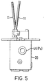
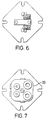
- the two operating levers 11 are seen in Figures 3 to 5.
- the lever 11 is normally in the rest position shown in Figure 2 in which supply pressure Ps is fully supplied as the output Px to both clutches, via the galleries 62 and 63 around the main valve spool 29.
- This output pressure Px is also supplied via drilling 44 and restrictor 8 to a first end 64 of the main valve spool 29 opposite the second end.
- This reduced Px is of course fed back to the first end of the spool 29 to maintain its balance, the balance of total pressure force acting on one end of the spool 29 against the force of the spring 32 acting on the other end.
- the spool position modulates to maintain this balance.
- Figure 8 is a graph of the pressure ports 46 (Px) of the two circuits against the movement (stroke) of the levers 11.
- the annulus formed at the first end 64 of the spool by the land 35 and reduced diameter portion 60 of the main valve spool 29 is typically 50% of the overall spool cross-sectional area, and the end of that spool formed in effect by the piston 60 is also typically 50% of the overall spool cross-sectional area but other percentages, ideally adding up to 100%, may be employed ideally totalling approximately 100% of the cross-sectional area.
- the supply pressure Ps is typically 25 bar and the diameter of the aperture 26 of the poppet valve 9 may be 2.5mm.
Landscapes
- Engineering & Computer Science (AREA)
- Mechanical Engineering (AREA)
- Physics & Mathematics (AREA)
- Fluid Mechanics (AREA)
- General Engineering & Computer Science (AREA)
- Transportation (AREA)
- Chemical & Material Sciences (AREA)
- Combustion & Propulsion (AREA)
- Automation & Control Theory (AREA)
- Fluid-Pressure Circuits (AREA)
- Non-Deflectable Wheels, Steering Of Trailers, Or Other Steering (AREA)
- Forklifts And Lifting Vehicles (AREA)
- Earth Drilling (AREA)
- Operation Control Of Excavators (AREA)
- Hydraulic Clutches, Magnetic Clutches, Fluid Clutches, And Fluid Joints (AREA)
- Mechanically-Actuated Valves (AREA)
- Safety Valves (AREA)
- Valve Device For Special Equipments (AREA)
Applications Claiming Priority (2)
| Application Number | Priority Date | Filing Date | Title |
|---|---|---|---|
| GB9805883 | 1998-03-20 | ||
| GB9805883A GB2335511B (en) | 1998-03-20 | 1998-03-20 | Hydraulic control means |
Publications (3)
| Publication Number | Publication Date |
|---|---|
| EP0943814A2 true EP0943814A2 (de) | 1999-09-22 |
| EP0943814A3 EP0943814A3 (de) | 2002-12-18 |
| EP0943814B1 EP0943814B1 (de) | 2004-09-29 |
Family
ID=10828873
Family Applications (1)
| Application Number | Title | Priority Date | Filing Date |
|---|---|---|---|
| EP99301460A Expired - Lifetime EP0943814B1 (de) | 1998-03-20 | 1999-02-26 | Hydraulische Steuervorrichtung |
Country Status (5)
| Country | Link |
|---|---|
| US (1) | US6192936B1 (de) |
| EP (1) | EP0943814B1 (de) |
| AT (1) | ATE278112T1 (de) |
| DE (1) | DE69920557T2 (de) |
| GB (1) | GB2335511B (de) |
Cited By (1)
| Publication number | Priority date | Publication date | Assignee | Title |
|---|---|---|---|---|
| WO2011091837A1 (de) * | 2010-01-29 | 2011-08-04 | Robert Bosch Gmbh | Hydraulisches vorsteuergerät |
Families Citing this family (2)
| Publication number | Priority date | Publication date | Assignee | Title |
|---|---|---|---|---|
| US20090050219A1 (en) * | 2007-08-21 | 2009-02-26 | Briggs And Stratton Corporation | Fluid compressor and control device for the same |
| DE102008031745A1 (de) * | 2008-07-04 | 2010-01-07 | Hydac Filtertechnik Gmbh | Hydraulische Ventilvorrichtung |
Family Cites Families (18)
| Publication number | Priority date | Publication date | Assignee | Title |
|---|---|---|---|---|
| NL71321C (de) * | 1941-10-20 | |||
| US3055383A (en) * | 1955-11-01 | 1962-09-25 | Ii William A Paine | Electro-hydraulic servo systems |
| US2913005A (en) * | 1956-07-23 | 1959-11-17 | Hughes Tool Co | Pilot-actuated control valve |
| US3304953A (en) * | 1964-01-02 | 1967-02-21 | Ohio Brass Co | Fluid power system and valve mechanisms therefor |
| US3646959A (en) * | 1970-10-12 | 1972-03-07 | Sperry Rand Corp | Power transmission |
| DE2158230C3 (de) * | 1971-11-24 | 1974-04-11 | Westinghouse Bremsen- Und Apparatebau Gmbh, 3000 Hannover | Hydraulische Steuereinrichtung |
| BE793325A (fr) * | 1971-12-27 | 1973-06-27 | Caterpillar Tractor Co | Système d'entrainement et de direction par voie hydraulique pour véhicules du type à chenilles. |
| JPS5032378A (de) * | 1973-07-24 | 1975-03-29 | ||
| US3967646A (en) * | 1974-05-13 | 1976-07-06 | Owatonna Tool Company | Three-way control valve |
| US4015619A (en) * | 1975-03-24 | 1977-04-05 | International Harvester Company | Clutch-brake steering mechanism for tractors |
| US4281676A (en) * | 1978-03-08 | 1981-08-04 | Caterpillar Tractor Co. | Pressure modulating selector valve |
| DE3031262C2 (de) * | 1980-08-19 | 1983-01-20 | Zahnradfabrik Friedrichshafen Ag, 7990 Friedrichshafen | Hydraulische Einrichtung zum gesteuerten/geregelten Druckverlauf in Kupplungen oder Bremsen |
| SE439342C (sv) * | 1981-09-28 | 1996-11-18 | Bo Reiner Andersson | Ventilanordning för styrning av en linjär eller roterande hydraulmotor |
| US4537220A (en) * | 1983-02-28 | 1985-08-27 | Sundstrand Corporation | Two member boost stage valve for a hydraulic control |
| US4685748A (en) * | 1984-12-24 | 1987-08-11 | The Boeing Company | Control system for aircraft wheel brakes and method |
| SE459271B (sv) * | 1987-10-27 | 1989-06-19 | Bahco Hydrauto Ab | Tryckmediumventil |
| DE3739824C2 (de) * | 1987-11-24 | 1994-09-29 | Rexroth Mannesmann Gmbh | Vorgesteuertes 3-Wege-Druckregelventil |
| US5042832A (en) * | 1988-01-29 | 1991-08-27 | Nissan Motor Company, Limited | Proportioning valve assembly and actively controlled suspension system utilizing the same |
-
1998
- 1998-03-20 GB GB9805883A patent/GB2335511B/en not_active Expired - Fee Related
-
1999
- 1999-02-26 EP EP99301460A patent/EP0943814B1/de not_active Expired - Lifetime
- 1999-02-26 AT AT99301460T patent/ATE278112T1/de not_active IP Right Cessation
- 1999-02-26 DE DE69920557T patent/DE69920557T2/de not_active Expired - Lifetime
- 1999-03-17 US US09/271,000 patent/US6192936B1/en not_active Expired - Fee Related
Non-Patent Citations (1)
| Title |
|---|
| None |
Cited By (5)
| Publication number | Priority date | Publication date | Assignee | Title |
|---|---|---|---|---|
| WO2011091837A1 (de) * | 2010-01-29 | 2011-08-04 | Robert Bosch Gmbh | Hydraulisches vorsteuergerät |
| CN102906430A (zh) * | 2010-01-29 | 2013-01-30 | 罗伯特·博世有限公司 | 液压预控制设备 |
| JP2013518227A (ja) * | 2010-01-29 | 2013-05-20 | ローベルト ボツシユ ゲゼルシヤフト ミツト ベシユレンクテル ハフツング | 液圧式のパイロット制御装置 |
| US8944104B2 (en) | 2010-01-29 | 2015-02-03 | Robert Bosch Gmbh | Hydraulic pilot control unit |
| CN102906430B (zh) * | 2010-01-29 | 2015-10-21 | 罗伯特·博世有限公司 | 液压预控制设备 |
Also Published As
| Publication number | Publication date |
|---|---|
| DE69920557D1 (de) | 2004-11-04 |
| EP0943814A3 (de) | 2002-12-18 |
| GB9805883D0 (en) | 1998-05-13 |
| EP0943814B1 (de) | 2004-09-29 |
| DE69920557T2 (de) | 2005-10-13 |
| US6192936B1 (en) | 2001-02-27 |
| GB2335511A (en) | 1999-09-22 |
| ATE278112T1 (de) | 2004-10-15 |
| GB2335511B (en) | 2002-01-30 |
Similar Documents
| Publication | Publication Date | Title |
|---|---|---|
| US4019602A (en) | Seat actuated fluid drive neutralizing arrangement | |
| US6871574B2 (en) | Hydraulic control valve assembly having dual directional spool valves with pilot operated check valves | |
| US3972267A (en) | Overruning load control for hydraulic jacks | |
| US7325885B2 (en) | Regulator valve for a torque-transmitting mechanism and method of engaging a torque-transmitting mechanism | |
| US9903396B2 (en) | Valve assembly | |
| CA1261231B (en) | Hydraulic circuit for activating a clutch and a throttle valve used in the circuit | |
| GB2516341A (en) | Flow responsive latch for holding a spool valve in an open position | |
| GB1564426A (en) | Combined steering and braking menas for crawler tractor | |
| US5907991A (en) | Quick drop valve control | |
| US4000795A (en) | Apparatus for controlling the pressure of a fluid fed to a clutch | |
| CA1037354A (en) | Control system for a fluid drive vehicle | |
| US3996840A (en) | Control circuit of actuator | |
| US6192936B1 (en) | Hydraulic control means | |
| US3837449A (en) | Transmission controlled spring applied steering brakes | |
| US6523636B2 (en) | Crawler motion control system | |
| US3143127A (en) | Regulating valve | |
| US4107924A (en) | Pump upgrading system | |
| US4093048A (en) | Vehicle steering brake and clutch control | |
| US4116214A (en) | Steering clutch and single pedal brake control system for crawler tractor | |
| US3595352A (en) | Clutch and brake with pressure operated sequencing valve | |
| US5129500A (en) | Control valve for timed clutch engagement | |
| US4150737A (en) | Inching valve | |
| CN115489593B (zh) | 转向流量控制阀、液压转向系统和轮式行走设备 | |
| US6021876A (en) | Electrical proportional pressure control valve | |
| US4106818A (en) | Braking system for vehicle |
Legal Events
| Date | Code | Title | Description |
|---|---|---|---|
| PUAI | Public reference made under article 153(3) epc to a published international application that has entered the european phase |
Free format text: ORIGINAL CODE: 0009012 |
|
| AK | Designated contracting states |
Kind code of ref document: A2 Designated state(s): AT BE CH CY DE DK ES FI FR GB GR IE IT LI LU MC NL PT SE |
|
| AX | Request for extension of the european patent |
Free format text: AL;LT;LV;MK;RO;SI |
|
| PUAL | Search report despatched |
Free format text: ORIGINAL CODE: 0009013 |
|
| AK | Designated contracting states |
Kind code of ref document: A3 Designated state(s): AT BE CH CY DE DK ES FI FR GB GR IE IT LI LU MC NL PT SE |
|
| AX | Request for extension of the european patent |
Free format text: AL;LT;LV;MK;RO;SI |
|
| 17P | Request for examination filed |
Effective date: 20030502 |
|
| AKX | Designation fees paid |
Designated state(s): AT BE CH CY DE DK ES FI FR GB GR IE IT LI LU MC NL PT SE |
|
| 17Q | First examination report despatched |
Effective date: 20030828 |
|
| GRAP | Despatch of communication of intention to grant a patent |
Free format text: ORIGINAL CODE: EPIDOSNIGR1 |
|
| GRAS | Grant fee paid |
Free format text: ORIGINAL CODE: EPIDOSNIGR3 |
|
| GRAA | (expected) grant |
Free format text: ORIGINAL CODE: 0009210 |
|
| AK | Designated contracting states |
Kind code of ref document: B1 Designated state(s): AT BE CH CY DE DK ES FI FR GB GR IE IT LI LU MC NL PT SE |
|
| PG25 | Lapsed in a contracting state [announced via postgrant information from national office to epo] |
Ref country code: NL Free format text: LAPSE BECAUSE OF FAILURE TO SUBMIT A TRANSLATION OF THE DESCRIPTION OR TO PAY THE FEE WITHIN THE PRESCRIBED TIME-LIMIT Effective date: 20040929 Ref country code: LI Free format text: LAPSE BECAUSE OF FAILURE TO SUBMIT A TRANSLATION OF THE DESCRIPTION OR TO PAY THE FEE WITHIN THE PRESCRIBED TIME-LIMIT Effective date: 20040929 Ref country code: FI Free format text: LAPSE BECAUSE OF FAILURE TO SUBMIT A TRANSLATION OF THE DESCRIPTION OR TO PAY THE FEE WITHIN THE PRESCRIBED TIME-LIMIT Effective date: 20040929 Ref country code: CH Free format text: LAPSE BECAUSE OF FAILURE TO SUBMIT A TRANSLATION OF THE DESCRIPTION OR TO PAY THE FEE WITHIN THE PRESCRIBED TIME-LIMIT Effective date: 20040929 Ref country code: BE Free format text: LAPSE BECAUSE OF FAILURE TO SUBMIT A TRANSLATION OF THE DESCRIPTION OR TO PAY THE FEE WITHIN THE PRESCRIBED TIME-LIMIT Effective date: 20040929 Ref country code: AT Free format text: LAPSE BECAUSE OF FAILURE TO SUBMIT A TRANSLATION OF THE DESCRIPTION OR TO PAY THE FEE WITHIN THE PRESCRIBED TIME-LIMIT Effective date: 20040929 |
|
| REG | Reference to a national code |
Ref country code: GB Ref legal event code: FG4D |
|
| REG | Reference to a national code |
Ref country code: CH Ref legal event code: EP |
|
| REG | Reference to a national code |
Ref country code: IE Ref legal event code: FG4D |
|
| REF | Corresponds to: |
Ref document number: 69920557 Country of ref document: DE Date of ref document: 20041104 Kind code of ref document: P |
|
| REG | Reference to a national code |
Ref country code: SE Ref legal event code: TRGR |
|
| PG25 | Lapsed in a contracting state [announced via postgrant information from national office to epo] |
Ref country code: GR Free format text: LAPSE BECAUSE OF FAILURE TO SUBMIT A TRANSLATION OF THE DESCRIPTION OR TO PAY THE FEE WITHIN THE PRESCRIBED TIME-LIMIT Effective date: 20041229 Ref country code: DK Free format text: LAPSE BECAUSE OF FAILURE TO SUBMIT A TRANSLATION OF THE DESCRIPTION OR TO PAY THE FEE WITHIN THE PRESCRIBED TIME-LIMIT Effective date: 20041229 |
|
| PG25 | Lapsed in a contracting state [announced via postgrant information from national office to epo] |
Ref country code: ES Free format text: LAPSE BECAUSE OF FAILURE TO SUBMIT A TRANSLATION OF THE DESCRIPTION OR TO PAY THE FEE WITHIN THE PRESCRIBED TIME-LIMIT Effective date: 20050109 |
|
| PG25 | Lapsed in a contracting state [announced via postgrant information from national office to epo] |
Ref country code: LU Free format text: LAPSE BECAUSE OF NON-PAYMENT OF DUE FEES Effective date: 20050226 Ref country code: CY Free format text: LAPSE BECAUSE OF FAILURE TO SUBMIT A TRANSLATION OF THE DESCRIPTION OR TO PAY THE FEE WITHIN THE PRESCRIBED TIME-LIMIT Effective date: 20050226 |
|
| PG25 | Lapsed in a contracting state [announced via postgrant information from national office to epo] |
Ref country code: MC Free format text: LAPSE BECAUSE OF NON-PAYMENT OF DUE FEES Effective date: 20050228 Ref country code: IE Free format text: LAPSE BECAUSE OF NON-PAYMENT OF DUE FEES Effective date: 20050228 |
|
| NLV1 | Nl: lapsed or annulled due to failure to fulfill the requirements of art. 29p and 29m of the patents act | ||
| REG | Reference to a national code |
Ref country code: CH Ref legal event code: PL |
|
| ET | Fr: translation filed | ||
| PLBE | No opposition filed within time limit |
Free format text: ORIGINAL CODE: 0009261 |
|
| STAA | Information on the status of an ep patent application or granted ep patent |
Free format text: STATUS: NO OPPOSITION FILED WITHIN TIME LIMIT |
|
| 26N | No opposition filed |
Effective date: 20050630 |
|
| REG | Reference to a national code |
Ref country code: IE Ref legal event code: MM4A |
|
| PG25 | Lapsed in a contracting state [announced via postgrant information from national office to epo] |
Ref country code: PT Free format text: LAPSE BECAUSE OF NON-PAYMENT OF DUE FEES Effective date: 20050228 |
|
| PGFP | Annual fee paid to national office [announced via postgrant information from national office to epo] |
Ref country code: SE Payment date: 20110209 Year of fee payment: 13 Ref country code: DE Payment date: 20110228 Year of fee payment: 13 Ref country code: IT Payment date: 20110221 Year of fee payment: 13 Ref country code: FR Payment date: 20110201 Year of fee payment: 13 |
|
| PGFP | Annual fee paid to national office [announced via postgrant information from national office to epo] |
Ref country code: GB Payment date: 20110124 Year of fee payment: 13 |
|
| GBPC | Gb: european patent ceased through non-payment of renewal fee |
Effective date: 20120226 |
|
| PG25 | Lapsed in a contracting state [announced via postgrant information from national office to epo] |
Ref country code: SE Free format text: LAPSE BECAUSE OF NON-PAYMENT OF DUE FEES Effective date: 20120227 |
|
| REG | Reference to a national code |
Ref country code: FR Ref legal event code: ST Effective date: 20121031 |
|
| PG25 | Lapsed in a contracting state [announced via postgrant information from national office to epo] |
Ref country code: IT Free format text: LAPSE BECAUSE OF NON-PAYMENT OF DUE FEES Effective date: 20120226 |
|
| REG | Reference to a national code |
Ref country code: DE Ref legal event code: R119 Ref document number: 69920557 Country of ref document: DE Effective date: 20120901 |
|
| PG25 | Lapsed in a contracting state [announced via postgrant information from national office to epo] |
Ref country code: FR Free format text: LAPSE BECAUSE OF NON-PAYMENT OF DUE FEES Effective date: 20120229 Ref country code: GB Free format text: LAPSE BECAUSE OF NON-PAYMENT OF DUE FEES Effective date: 20120226 |
|
| PG25 | Lapsed in a contracting state [announced via postgrant information from national office to epo] |
Ref country code: DE Free format text: LAPSE BECAUSE OF NON-PAYMENT OF DUE FEES Effective date: 20120901 |