EP0943837A2 - Tête de réduction pour machine-outil - Google Patents
Tête de réduction pour machine-outil Download PDFInfo
- Publication number
- EP0943837A2 EP0943837A2 EP98500142A EP98500142A EP0943837A2 EP 0943837 A2 EP0943837 A2 EP 0943837A2 EP 98500142 A EP98500142 A EP 98500142A EP 98500142 A EP98500142 A EP 98500142A EP 0943837 A2 EP0943837 A2 EP 0943837A2
- Authority
- EP
- European Patent Office
- Prior art keywords
- pinion
- gear
- main axis
- machine tool
- motor
- Prior art date
- Legal status (The legal status is an assumption and is not a legal conclusion. Google has not performed a legal analysis and makes no representation as to the accuracy of the status listed.)
- Withdrawn
Links
- 230000008878 coupling Effects 0.000 claims abstract description 4
- 238000010168 coupling process Methods 0.000 claims abstract description 4
- 238000005859 coupling reaction Methods 0.000 claims abstract description 4
- 239000003638 chemical reducing agent Substances 0.000 claims 1
- 230000005540 biological transmission Effects 0.000 description 4
- 238000010586 diagram Methods 0.000 description 2
- 230000009365 direct transmission Effects 0.000 description 1
- 238000003754 machining Methods 0.000 description 1
Images

Classifications
-
- F—MECHANICAL ENGINEERING; LIGHTING; HEATING; WEAPONS; BLASTING
- F16—ENGINEERING ELEMENTS AND UNITS; GENERAL MEASURES FOR PRODUCING AND MAINTAINING EFFECTIVE FUNCTIONING OF MACHINES OR INSTALLATIONS; THERMAL INSULATION IN GENERAL
- F16H—GEARING
- F16H3/00—Toothed gearings for conveying rotary motion with variable gear ratio or for reversing rotary motion
- F16H3/02—Toothed gearings for conveying rotary motion with variable gear ratio or for reversing rotary motion without gears having orbital motion
- F16H3/08—Toothed gearings for conveying rotary motion with variable gear ratio or for reversing rotary motion without gears having orbital motion exclusively or essentially with continuously meshing gears, that can be disengaged from their shafts
- F16H3/087—Toothed gearings for conveying rotary motion with variable gear ratio or for reversing rotary motion without gears having orbital motion exclusively or essentially with continuously meshing gears, that can be disengaged from their shafts characterised by the disposition of the gears
- F16H3/091—Toothed gearings for conveying rotary motion with variable gear ratio or for reversing rotary motion without gears having orbital motion exclusively or essentially with continuously meshing gears, that can be disengaged from their shafts characterised by the disposition of the gears including a single countershaft
- F16H3/0915—Toothed gearings for conveying rotary motion with variable gear ratio or for reversing rotary motion without gears having orbital motion exclusively or essentially with continuously meshing gears, that can be disengaged from their shafts characterised by the disposition of the gears including a single countershaft with coaxial input and output shafts
Definitions
- the present invention deals with a reduction head of the type of those, coupled to a motor axis with an initial speed, transmitting this movement of turn to an output axis at a different final speed - and generally lower.
- the application of the reduction head according to the invention is intended for machine tool (in particular machining machine tool comprising a tool holder located on its main axis), even if we hardly move aside other applications without varying the invention in its essence.
- the present invention relates to an improved reduction head, preferably applied in machine tools.
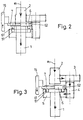
- the recommended head includes a carcass integrated by several removable covers (8), (9), (10) (11) which allow the passage of input axes (e 1 ) motor and output or main axis (1) on which is arranged, for example, a tool holder.
- a gear train (3), (4), (5) mounted on the covers (10), (11) of the carcass allows movement from the motor pinion (2), at reduced speed.
- the pinions (3), (4) of the gear train (3), (4), (5) are arranged on a auxiliary axis (1a) mounted on the covers (10), (11) of the carcass with interposition of bearings (13), (13 ').
- the main axis (1) carries the change gear (6).
- the change gear (6) has means for meshing directly on the pinion (2) or lock on the last pinion (5) of the train gears (3), (4), (5), at the discretion of the user when the latter acts on appropriate selector means.
- the selector means are, for the embodiment shown, a coach internal (7) and an external guided control (15) which is integral with it.
- the internal trainer (7) is permanently housed in a guide circumferential (62) of the change gear (6).
- Said means of coupling / uncoupling between pinion (5) and change gears (6) are, for the embodiment shown, sets of protrusions (61) on the gear (6) which, depending on their position, are housed or not in mortise games (51) whose positions face each other.
- the change gear (6) being in an extreme position - reached by the trainer (7) by manipulating the control (15), the protrusions (61) are released from the mortises (51) and the change gear (6) meshes on the motor pinion (2).
- the rotational movement is transmitted directly from the axis (e1) through the drive pinion (2) and the change gear (6) to the main axis (1).
- the gear train (3), (4) (5) turns freely.
- the change gear (6) being in another position extreme - obtained by the trainer (7) by manipulating the control (15) - the protrusions (61) are housed in the mortises (51) and the gear of change (6) - free from the pinion (2) - turns integral with the pinion (5).
- the movement is transmitted - reduced - from the axis (e1) through the motor pinion (2) and gear train (3), (4), (5), (6) to the main axis (1).
Landscapes
- Engineering & Computer Science (AREA)
- General Engineering & Computer Science (AREA)
- Mechanical Engineering (AREA)
- Structure Of Transmissions (AREA)
- Gear Transmission (AREA)
Abstract
Description
Claims (3)
- Tête de réduction perfectionnée, pour machine-outil, se caractérisant par le fait de disposer, sur une carcasse démontable, de:a) un pignon moteur (2) monté sur l'axe de sortie (e1) du moteur, avec lequel il tourne de manière permanente et solidaire;b) un train d'engrenages comprenant un premier pignon (3) engrené en permanence avec le pignon moteur (2) et un dernier pignon (5) qui tourne en permanence à vitesse réduite;c) un engrenage de changement (6) disposé de manière coaxiale par rapport à l'axe principal (1) et susceptible d'adopter au moins deux positions d'opérations dans lesquelles, respectivement, il engrène sur ledit pignon-moteur (2) en transmettant à l'axe principal (1) une vitesse directe et s'accouple de manière verrouillée sur ledit dernier pignon (5) du train d'engrenages réducteur avec lequel il tourne de manière solidaire en transmettent à l'axe principal (1) une vitesse réduite;d) des moyens d'accouplement/désaccouplement entre lesdits engrenage de changement (6) et le dernier pignon (5) pour transmettre respectivement, la vitesse directe et la vitesse réduite à l'axe principal (1);e) des moyens sélecteur (15), (7) pour disposer de manière axiale l'engrenage de changement (6) dans l'une ou l'autre de ses positions d'opérations.
- Tête de réduction perfectionnée, pour machine-outil, selon revendication antérieure, se caractérisant par le fait que les dits moyens d'accouplement/désaccouplement sont constitués, sur l'engrenage de changement (6) par un jeu de protubérances (61) et sur le dernier pignon (5) par un jeu de mortaises (51) qui les logent conjointement ou les libère en fonction de la position axiale de l'engrenage (6) déplacé linéairement par les moyens sélecteurs (15, 7).
- Tête de réduction perfectionnée, Pour machine-outil, selon revendications antérieures, se caractérisant par le fait que les dits moyens sélecteurs sont constitués par une commande (15) guidée dans la carcasse du réducteur et solidaire d'un entraíneur interne, logé èn permanence dans un guide circonférentiel de l'engrenage de changement (6) qu'il déplace de manière axiale en agissant sur la commande (15).
Applications Claiming Priority (2)
| Application Number | Priority Date | Filing Date | Title |
|---|---|---|---|
| ES9800726U ES1039749Y (es) | 1998-03-16 | 1998-03-16 | Cabezal reductor perfeccionado, para maquina-herramienta. |
| ES9800726U | 1998-03-16 |
Publications (2)
| Publication Number | Publication Date |
|---|---|
| EP0943837A2 true EP0943837A2 (fr) | 1999-09-22 |
| EP0943837A3 EP0943837A3 (fr) | 2001-03-28 |
Family
ID=8303362
Family Applications (1)
| Application Number | Title | Priority Date | Filing Date |
|---|---|---|---|
| EP98500142A Withdrawn EP0943837A3 (fr) | 1998-03-16 | 1998-06-16 | Tête de réduction pour machine-outil |
Country Status (2)
| Country | Link |
|---|---|
| EP (1) | EP0943837A3 (fr) |
| ES (1) | ES1039749Y (fr) |
Cited By (1)
| Publication number | Priority date | Publication date | Assignee | Title |
|---|---|---|---|---|
| SE1751387A1 (en) * | 2017-11-09 | 2019-05-10 | Scania Cv Ab | A gearbox, a powertrain and a vehicle |
Families Citing this family (1)
| Publication number | Priority date | Publication date | Assignee | Title |
|---|---|---|---|---|
| CN112658293A (zh) * | 2020-12-08 | 2021-04-16 | 珠海格力电器股份有限公司 | 方便拆装的轴芯组件及电主轴 |
Family Cites Families (3)
| Publication number | Priority date | Publication date | Assignee | Title |
|---|---|---|---|---|
| BE354724A (fr) * | 1927-10-05 | 1900-01-01 | ||
| US4019400A (en) * | 1974-12-16 | 1977-04-26 | Stump James M | Auxiliary two-speed transmission |
| US4485692A (en) * | 1982-06-17 | 1984-12-04 | Moore Jeff D | Auxiliary transmission |
-
1998
- 1998-03-16 ES ES9800726U patent/ES1039749Y/es not_active Expired - Fee Related
- 1998-06-16 EP EP98500142A patent/EP0943837A3/fr not_active Withdrawn
Non-Patent Citations (1)
| Title |
|---|
| None |
Cited By (1)
| Publication number | Priority date | Publication date | Assignee | Title |
|---|---|---|---|---|
| SE1751387A1 (en) * | 2017-11-09 | 2019-05-10 | Scania Cv Ab | A gearbox, a powertrain and a vehicle |
Also Published As
| Publication number | Publication date |
|---|---|
| ES1039749U (es) | 1999-01-16 |
| ES1039749Y (es) | 1999-06-01 |
| EP0943837A3 (fr) | 2001-03-28 |
Similar Documents
| Publication | Publication Date | Title |
|---|---|---|
| EP0224407B1 (fr) | Boîte de vitesses mécanique à un arbre primaire et à deux arbres secondaires | |
| FR2460221A1 (fr) | Dispositif de prise de force pour tracteur | |
| FR2579711A1 (fr) | Boite de vitesses pour vehicule a moteur | |
| FR2693527A1 (fr) | Ensemble de transmission à boîte de vitesses et différentiel et groupe moto-propulseur pour véhicule automobile muni d'un tel ensemble. | |
| CA1148093A (fr) | Transmission de motocyclette | |
| EP2627928B1 (fr) | Boîte de vitesses pour équipement de motoculture et équipement de motoculture comprenant une telle boîte de vitesses | |
| EP0643239B1 (fr) | Boíte de vitesse à embrayage incorporé | |
| EP1172175B1 (fr) | Système de modularité applicable au bélier-tête d'une fraiseuse | |
| FR2880088A1 (fr) | Boite de vitesses de vehicule automobile | |
| EP3456479B1 (fr) | Dispositif d'entraînement pour une machine-outil motorisée | |
| EP0847837A2 (fr) | Transmission à plusieurs vitesses pour un outil à main motorisé | |
| FR2531515A1 (en) | Gearbox with integrated range doubler. | |
| EP0554629B1 (fr) | Machine de rodage par expansion | |
| FR2829952A1 (fr) | Machine d'usinage a mecanisme d'entrainement standardise | |
| DE10151699B4 (de) | Bohrhammer | |
| FR2833540A1 (fr) | Element de renvoi pour mecanisme de changement de rapports de boite de vitesses | |
| CN224214643U (zh) | 一种摩托车发动机的换挡结构 | |
| EP0943837A3 (fr) | Tête de réduction pour machine-outil | |
| BRPI0403187B1 (pt) | estrutura de conexão entre engrenagem plástica e eixo | |
| JPS58593Y2 (ja) | 農用トラクタ−等における変速操作装置 | |
| CH636795A5 (en) | Electric hammer drill | |
| SU770676A1 (ru) | Привод шпиндел | |
| EP1013377B1 (fr) | Outil motorisé | |
| JP3960892B2 (ja) | 作業機における作業装置の角度可変機構 | |
| EP1757843B1 (fr) | Couvercle pour une boîte de vitesses |
Legal Events
| Date | Code | Title | Description |
|---|---|---|---|
| PUAI | Public reference made under article 153(3) epc to a published international application that has entered the european phase |
Free format text: ORIGINAL CODE: 0009012 |
|
| AK | Designated contracting states |
Kind code of ref document: A2 Designated state(s): AT BE CH CY DE DK ES FI FR GB GR IE IT LI LU MC NL PT SE |
|
| AX | Request for extension of the european patent |
Free format text: AL;LT;LV;MK;RO;SI |
|
| 17P | Request for examination filed |
Effective date: 19991208 |
|
| PUAL | Search report despatched |
Free format text: ORIGINAL CODE: 0009013 |
|
| AK | Designated contracting states |
Kind code of ref document: A3 Designated state(s): AT BE CH CY DE DK ES FI FR GB GR IE IT LI LU MC NL PT SE |
|
| AX | Request for extension of the european patent |
Free format text: AL;LT;LV;MK;RO;SI |
|
| STAA | Information on the status of an ep patent application or granted ep patent |
Free format text: STATUS: THE APPLICATION HAS BEEN WITHDRAWN |
|
| 18W | Application withdrawn |
Withdrawal date: 20010517 |