EP0943980A2 - Rechnerüberwachungsvorrichtung - Google Patents
Rechnerüberwachungsvorrichtung Download PDFInfo
- Publication number
- EP0943980A2 EP0943980A2 EP99105387A EP99105387A EP0943980A2 EP 0943980 A2 EP0943980 A2 EP 0943980A2 EP 99105387 A EP99105387 A EP 99105387A EP 99105387 A EP99105387 A EP 99105387A EP 0943980 A2 EP0943980 A2 EP 0943980A2
- Authority
- EP
- European Patent Office
- Prior art keywords
- power supply
- circuit
- computer
- microcomputer
- signal
- Prior art date
- Legal status (The legal status is an assumption and is not a legal conclusion. Google has not performed a legal analysis and makes no representation as to the accuracy of the status listed.)
- Ceased
Links
Images



Classifications
-
- G—PHYSICS
- G06—COMPUTING OR CALCULATING; COUNTING
- G06F—ELECTRIC DIGITAL DATA PROCESSING
- G06F1/00—Details not covered by groups G06F3/00 - G06F13/00 and G06F21/00
- G06F1/26—Power supply means, e.g. regulation thereof
- G06F1/30—Means for acting in the event of power-supply failure or interruption, e.g. power-supply fluctuations
Definitions
- the present invention relates to a computer monitoring device for monitoring whether a normal operation is being carried out by a computer applied to control upward and downward movements of a window in a power window system for a vehicle, and detection of nipping of foreign matter by the window, or the like.
- the microcomputer is operated by a stabilized power supply, which is controlled to have a constant voltage on the basis of a voltage energized from a battery (about 5 V).
- a microcomputer monitoring circuit i.e., a so-called watchdog timer circuit.
- the microcomputer when the microcomputer is operating normally, it outputs a pulse signal to the microcomputer monitoring circuit in a predetermined cycle. While this pulse signal is being detected by the microcomputer monitoring circuit, the microcomputer is thereby judged to be operating normally.
- the microcomputer monitoring circuit assesses that the microcomputer is in an abnormal state. Then, the microcomputer monitoring circuit outputs a signal for prohibiting signal processing circuit from communicating with the microcomputer to the signal processing circuit, which outputs a signal for operating a power window, so as to prevent the power window from malfunctioning. Then, the microcomputer monitoring circuit outputs a reset signal to the microcomputer so as to restart the microcomputer.
- the microcomputer monitoring circuit is also employed for the power source supplied to the microcomputer, when the power supply voltage supplied to the microcomputer decreases, the power supply voltage supplied to the microcomputer monitoring circuit also decreases. As a result, there arises a problem in that it is no longer possible to ensure safe operation for preventing the power window from malfunctioning or the like when the microcomputer is in an abnormal state.
- a first aspect of the present invention is a computer monitoring device provided at a controller which operates a device to be controlled in accordance with a program built into a computer, comprising: a power supply circuit that supplies power to the computer; a monitoring circuit that is operated by the power supplied from the power supply circuit and monitors an operational state of the computer; an abnormality processing circuit that is operated by the power supplied from the power supply circuit and performs processing when the computer is operating abnormally; an auxiliary power supply that can supply power to at least one of the monitoring circuit and the abnormality processing circuit; and switching means that switches from the power supply circuit to the auxiliary power supply when a voltage value of the power supplied from the power supply circuit decreases to a value lower than a predetermined voltage value.
- the present aspect may comprise voltage detecting means that detects the voltage of the power supply circuit, and switching control means which, on a basis of detection results of the voltage detecting means, switches from the power supply circuit to the auxiliary power supply when the voltage decreases to a value lower than a predetermined value.
- the auxiliary power supply is provided for cases in which the power supply voltage supplied from the power supply circuit decreases.
- the switching means switches from the power supply circuit to the auxiliary power supply.
- the present first aspect may comprise voltage detecting means that detects the voltage of the power supply circuit, and switching control means which, on a basis of detection results of the voltage detecting means, when the voltage decreases to a value lower than a predetermined value, switches from the power supply circuit to the auxiliary power supply. In this case, on the basis of the detection results of the voltage detecting means, the switching control means switches from the power supply circuit to the auxiliary power supply.
- a second aspect of the present invention is a computer monitoring device according to the first aspect of the present invention, wherein the switching means or the switching control means is a pair of diodes whose anode sides are respectively connected to an output end of the power supply circuit and an output end of the auxiliary power supply, and whose cathode sides are connected to each other.
- the switching means or the switching control means is a pair of diodes whose anode sides are respectively connected to an output end of the power supply circuit and an output end of the auxiliary power supply, and whose cathode sides are connected to each other. Accordingly, the power supply circuit can be switched to the auxiliary power supply through a simple structure, and the power supply circuit and the auxiliary power supply are prevented from interfering with each other.
- a third aspect of the present invention is a computer monitoring device provided at a controller which operates a device to be controlled in accordance with a program built into a computer, comprising: a power supply circuit controlling a voltage supplied from the power supply to be a constant voltage, and supplying power to the computer; a monitoring circuit that is operated by the power supplied from the power supply circuit and monitors an operational state of the computer; an abnormality processing circuit that is operated by the power supplied from the power supply circuit and performs processing when the computer is operating abnormally; an auxiliary power supply that can supply power to at least one of the monitoring circuit and the abnormality processing circuit; an overcurrent detecting circuit that detects an overcurrent supplied to the power supply circuit; and switching control means that, on a basis of a signal output from the overcurrent detecting circuit, switches from the power supply circuit to the auxiliary power supply.
- the auxiliary power supply is provided for cases where the power supply voltage supplied from the power supply circuit decreases.
- the switching control means switches from the power supply circuit to the auxiliary power supply. Accordingly, power is supplied from the auxiliary power supply to the abnormality processing circuit. As a result, the abnormality processing circuit can continue to operate, and it is possible to perform processing for ensuring safe operation.
- the fourth aspect of the present invention is the computer monitoring device wherein the auxiliary power supply operates effectively only when a predetermined signal is inputted.
- the operation of the auxiliary power supply is effective only when the predetermined signal is inputted, namely only when safe operation must be ensured, an increase in consumption of electrical current in a waiting state in which a signal is not inputted can be prevented.
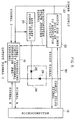
- a computer monitoring device 10 is shown in Fig. 1.
- This computer monitoring device 10 includes a microcomputer 12 comprising a CPU, a RAM, a ROM, and various interfaces, which are not shown in the figures and which are connected to each other via buses, a microcomputer monitoring circuit 14, signal processing circuit 16, a microcomputer power supply 18, and an auxiliary power supply 20.
- the signal processing circuit 16 signal processing is performed in accordance with an inputted signal 1 and a signal 2, and the processed signal is transmitted as a signal A to the microcomputer 12.
- the microcomputer 12 performs processing on the basis of the signal A outputted from the signal processing circuit 16, and outputs a signal B to the signal processing circuit 16.
- the signal processing circuit 16 performs signal processing, and outputs an output signal C.
- the signal 1 is an ignition signal for a vehicle
- the signal 2 is an UP signal or a DOWN signal for vertically moving a door glass 100, which will be described later
- the output signal C is a signal for driving a motor 52 for vertically moving the door glass 100, which will be described later.
- FIG. 2 An internal structure of a door 42 at a driver's seat side of a vehicle is shown in Fig. 2.
- the motor 52 is provided inside a door at the driver's seat side.
- a window regulator portion 46 is connected to the motor 52.
- the window regulator portion 46 is a so-called wire type.
- An intermediate portion of a wire (not shown) is rolled around a rotating plate 52A which is mounted to a driving shaft of the motor 52.
- Each of the end portions of this wire is connected to a holding channel 54 for supporting the lower end portion of the door glass 100.
- the holding channel 54 is attached to a main guide 56 so as to be vertically movable along the main guide 56.
- a structure of the window regulator portion 46 is not limited to such a wire type as described above. Instead, an X arm type or a so-called motor self-traveling type in which the motor itself moves along a rack can be employed.
- a peripheral end portion of the door glass 100 is fitted into a weather strip, which is made from a rubber (not shown) within a frame 42A of the door 42, and an opening with respect to the frame 42A is closed. Further, due to rotation driving of the motor 52, when the door glass 100 moves downwardly, the opening with respect to the frame 42A of the door 42 is opened.
- an unillustrated switch In order to move the door glass 100 vertically, an unillustrated switch is operated, and when an UP signal or a DOWN signal is inputted as the signal 2 to the signal processing circuit 16, on the basis of the signal 2, the signal processing circuit 16 performs signal processing, and transmits the processed signal as a signal A to the microcomputer 12.
- the microcomputer 12 In accordance with the signal A, the microcomputer 12 performs signal processing, and outputs a signal B to the signal processing circuit 16. Thereafter, in accordance with the signal B, the signal processing circuit 16 performs signal processing, outputs the output signal C for driving the motor 52, drives the motor 52, and moves the door glass 100 vertically.
- the microcomputer monitoring circuit 14 for detecting abnormal operation of the microcomputer 12 is connected to the microcomputer 12.
- the microcomputer 12 outputs a cancel pulse signal to the microcomputer monitoring circuit 14 in a predetermined cycle. Further, the microcomputer 12 is restarted by a reset signal outputted from the microcomputer monitoring circuit 14.
- the microcomputer monitoring circuit 14 assesses that the microcomputer 12 is operating normally. Accordingly, the microcomputer monitoring circuit 14 does not output a reset signal to the microcomputer 12, and sets a microcomputer state determination signal, which is output to the signal processing circuit 16, to be normal (for example, at a high level).
- the microcomputer monitoring circuit 14 assesses that the microcomputer 12 is abnormal, outputs the reset signal to the microcomputer 12, restarts the microcomputer 12, and sets the microcomputer state determination signal, which is outputted to the signal processing circuit 16, to be abnormal (for example, at a low level).
- the signal processing circuit 16 is prohibited from communicating with the microcomputer 12. Namely, transmitting the signal A or receiving the signal B is prohibited, and the signal processing circuit 16 outputs the output signal C (e.g., a motor stopping signal) so as to prevent the door glass 100 from operating abnormally.
- the microcomputer monitoring circuit 14 outputs the reset signal to the microcomputer 12, restarts the microcomputer 12, operates in the same way as when the microcomputer monitoring circuit 14 can not detect the cancel pulse signal for a predetermined period of time or more.
- the microcomputer power supply 18 is connected to the microcomputer monitoring circuit 14 and the microcomputer 12, converts the voltage supplied from a power supply 22 to a predetermined voltage (in the present embodiment, for example, 5V), and supplies the voltage to the microcomputer monitoring circuit 14 and the microcomputer 12. Further, an anode side of a diode 24 is connected to the microcomputer power supply 18, and a cathode side of the diode 24 is connected to the cathode side of a diode 26, the microcomputer monitoring circuit 14, and the signal processing circuit 16.
- a predetermined voltage in the present embodiment, for example, 5V
- An anode side of the diode 26 is connected to an auxiliary power supply 20, and the cathode side of the diode 26 is connected to the cathode side of the diode 24, the microcomputer monitoring circuit 14, and the signal processing circuit 16.
- the auxiliary power supply 20 converts the voltage supplied from the power supply 22 to a voltage that is slightly lower than the voltage supplied from the microcomputer power supply 18 and is a voltage at which the microcomputer monitoring circuit 14 and the signal processing circuit 16 can operate (in the present embodiment, for example, 4V), and supplies the voltage to the microcomputer monitoring circuit 14 and the signal processing circuit 16 via the diode 26.
- the potential at a point D which is shown in Fig. 1, is about 4.3V. Therefore, since the potential at the point D is higher than that of the auxiliary power supply 20, a current does not flow into the diode 26, and a current supplied from the microcomputer power supply 18 is supplied to the microcomputer monitoring circuit 14 and the signal processing circuit 16 via the diode 24. Namely, a structure is adopted that automatically switches from the microcomputer power supply 18 to the auxiliary power supply 20.
- the power supply voltage supplied from the microcomputer power supply 18 decreases due to a short circuit of a power supply-ground, for example, the potential at the point D also decreases, and the potential at the auxiliary power supply 20 becomes higher than the potential at the point D. Accordingly, the current supplied from the auxiliary power supply 20 is supplied to the microcomputer monitoring circuit 14 and the signal processing circuit 16 via the diode 26.
- a voltage decrease detecting signal can also be outputted to the auxiliary power supply 20.
- the auxiliary power supply 20 converts the voltage supplied from the power supply 22 to a predetermined voltage (in the present embodiment, for example, 5V), and supplies the voltage to the microcomputer monitoring circuit 14 and the signal processing circuit 16 via the diode 26.
- the auxiliary power supply 20 samples the voltage decrease detecting signal outputted from the microcomputer power supply 18, and operates only when the voltage level of this voltage decrease detecting signal is lower than or equal to a predetermined voltage level (for example, 3V).
- the auxiliary power supply 20 is thereby operated so as to supply power to the microcomputer monitoring circuit 14 and the signal processing circuit 16 via the diode 26.
- microcomputer power supply 18 When the microcomputer power supply 18 is normal, power is supplied from the microcomputer power supply 18 to the microcomputer monitoring circuit 14 and the signal processing circuit 16. When the microcomputer power supply 18 is abnormal, power is supplied from the auxiliary power supply 20 to the microcomputer monitoring circuit 14 and the signal processing circuit 16.
- the microcomputer power supply 18 and the auxiliary power supply 20 can be prevented from interfering with each other via a diode OR circuit 28, which is formed with the diodes 24 and 26.
- An ignition signal (the signal 1) is inputted to the auxiliary power supply 20.
- the auxiliary power supply 20 operates only when this ignition signal is on (since the power window can move, it is necessary to ensure safe operation). Accordingly, when the ignition signal is off, i.e., in a waiting state (since the power window can not move, it is not necessary to ensure safe operation), an increase in consumption of electrical current is prevented.
- auxiliary power supply 20 is made to operate effectively when the ignition signal is off, it is also possible to apply the auxiliary power supply 20 to a burglary prevention system.
- Start-up of the microcomputer 12 begins, when it receives power supplied from the microcomputer power supply 18. Simultaneous with start-up of the microcomputer 12, the microcomputer monitoring circuit 14 begins to monitor whether the microcomputer 12 is operating normally. The microcomputer monitoring circuit 14 assesses that the microcomputer 12 is in a normal state while the microcomputer monitoring circuit 14 detects the cancel pulse signal outputted from the microcomputer 12, and sets the microcomputer state determination signal, which is outputted to the signal processing circuit 16, at a high level (normal).
- An unillustrated switch for vertically moving the door glass 100 is operated.
- the signal processing circuit 16 performs processing on the basis of the signal 2, and the processed signal is transmitted as the signal A to the microcomputer 12.
- the microcomputer 12 performs processing, and the signal B is transmitted to the signal processing circuit 16.
- the signal processing circuit 16 carries out processing, outputs the output signal C for driving the motor 52, drives the motor 52, and thereby moves the door glass 100 vertically.
- the potential at the point D When the power supply voltage supplied from the microcomputer power supply 18 decreases and the microcomputer 12 is in an abnormal state, the potential at the point D also decreases. Accordingly, the potential at the auxiliary power supply 20 becomes higher than the potential at the point D, and the current supplied from the auxiliary power supply 20 is supplied to the microcomputer monitoring circuit 14 and the signal processing circuit 16 via the diode 26. As a result, the microcomputer monitoring circuit 14 and the signal processing circuit 16 can continue to operate normally.
- a voltage decrease detecting signal is outputted to the auxiliary power supply 20, when the power supply voltage supplied from the microcomputer power supply 18 decreases, and the microcomputer 12 is in an abnormal state, the voltage level of the voltage decrease detecting signal decreases. Accordingly, the auxiliary power supply 20 operates so as to supply power to the microcomputer monitoring circuit 14 and the signal processing circuit 16 via the diode 26. Therefore, the microcomputer monitoring circuit 14 and the signal processing circuit 16 can continue to operate normally.
- the microcomputer monitoring circuit 14 Since the microcomputer is in an abnormal state, the microcomputer monitoring circuit 14 outputs the reset signal to the microcomputer 12, restarts the microcomputer 12, and sets the microcomputer state determination signal at a low level (abnormal).
- the signal processing circuit 16 Since the microcomputer state determination signal outputted from the microcomputer monitoring circuit 14 is abnormal, the signal processing circuit 16 is prohibited from communicating with the microcomputer 12. Namely, transmitting the signal A and receiving the signal B is prohibited, and the signal processing circuit 16 outputs a motor stopping signal as the output signal C so as to prevent the vertical movement of the door glass 100 from operating abnormally. As a result, the door glass 100 does not operate abnormally.
- auxiliary power supply 20 Since the auxiliary power supply 20 operates only when the ignition signal (the signal 1) is on (since the power window can move, it is necessary to ensure safe operation), when the ignition signal is off, i.e., in a waiting state (since the power window can not move, it is not necessary to ensure safe operation), excessive consumption of electrical current can be prevented.
- the signal 1 can be inputted as the power supply input to the auxiliary power supply 20 so as to operate the auxiliary power supply 20 as shown in Fig. 3.
- the microcomputer monitoring circuit 14 can be structured such that the microcomputer state determination signal outputted from the microcomputer monitoring circuit 14 is reliably set to be abnormal, when the power supply voltage supplied from the microcomputer power supply 18 decreases, it is thereby possible to eliminate an auxiliary power supply line 34, which is shown by a dashed line in this figure.
- FIG. 4 Another example of a computer monitoring device according to the present invention is shown in Fig. 4. Portions identical to those of the computer monitoring device 10, which is shown in Fig. 1, are denoted by the same reference numerals, and a detailed description thereof will be omitted.
- a computer monitoring device 30, which is shown in Fig. 4, has a watchdog timer built-in 5V regulator circuit 32, which has a watchdog timer (a microcomputer monitoring circuit) built therein.
- the watchdog timer built-in 5V regulator circuit 32 converts the power supply voltage supplied from the power supply 22 to 5V, supplies the voltage to the signal processing circuit 16 and the microcomputer 12, and monitors the operational state of the microcomputer 12.
- the microcomputer state determination signal is set at a high level (normal). While the microcomputer 12 is operating abnormally (while the cancel pulse signal is not detected by the watchdog timer built-in 5V regulator circuit 32, for a predetermined period of time or more), the watchdog timer built-in 5V regulator circuit 32 outputs the reset signal to the microcomputer 12, restarts the microcomputer 12, and sets the microcomputer state determination signal at a low level (abnormal). In this case, since the microcomputer 12 is in an abnormal state, the signal processing circuit 16 outputs the motor stopping signal as the output signal C, prevents the door glass 100 from operating abnormally, and ensures safe operation.
- the signal processing circuit 16 performs processing for ensuring safe operation in the same manner as described above.
- the signal 1 can also be used as the power supply input, the signal 1 can be inputted as the power supply input to the auxiliary power supply 20 so as to operate the auxiliary power supply 20 as shown in Fig. 5.
- FIG. 6 Yet another example of a computer monitoring device according to the present invention is shown in Fig. 6. Portions identical to those of the computer monitoring device 10 in Fig. 1 are denoted by the same reference numerals, and a detailed description thereof will be omitted.
- the computer monitoring device 30 shown in Fig. 6 has an overcurrent detecting circuit 36.
- the input end of the overcurrent detecting circuit 36 is connected to the power supply 22, and one output end of the overcurrent detecting circuit 36 is connected to the microcomputer power supply 18 and the other is connected to the auxiliary power supply 20.
- the microcomputer power supply 18 When the overcurrent detecting circuit 36 does not detect an overcurrent (normal), the microcomputer power supply 18 operates. When the overcurrent detecting circuit 36 detects an overcurrent (abnormal), a switch is made to the auxiliary power supply 20. For this reason, even when the voltage outputted from the microcomputer power supply 18 decreases due to an overcurrent, power is supplied from the auxiliary power supply 20 to the microcomputer monitoring circuit 14 and the signal processing circuit 16 so that processing can be continued. In this case, since the microcomputer state determination signal is set at a low level (abnormal), the signal processing circuit 16 performs processing for ensuring safe operation.
- microcomputer monitoring circuit 14 can be structured such that the microcomputer state determination signal outputted from the microcomputer monitoring circuit 14 is reliably set to be abnormal when the power supply voltage supplied from the microcomputer power supply 18 decreases, an auxiliary power supply line 38, which is shown by a dashed line in this figure, can be eliminated.
- the present invention is not limited to this; needless to say, the present invention can be applied to an air bag system or the like.
- an auxiliary power supply is provided for cases in which the power supply voltage supplied from a power supply circuit decreases.
- the structure is such that the auxiliary power supply supplies power to a monitoring circuit for monitoring the state of the operation of a computer, and to an abnormality processing circuit which performs processing against abnormal operation of the computer when the computer operates abnormally.
- the monitoring circuit and the abnormality processing circuit can continue to operate, and processing for ensuring safe operation can be performed.
- switching means are a pair of diodes whose anode sides are connected to an output end of each of the power supply circuit and the auxiliary power supply, and whose cathode sides are connected to each other. Accordingly, the power supply circuit can be switched to the auxiliary power supply in a simple manner. As a result, it is possible to prevent the power supply circuit and the auxiliary power supply from interfering with each other.
- the auxiliary power supply is caused to operate effectively only when a predetermined signal is inputted, namely, only in cases in which safe operation must be ensured. As a result, an increase in consumption of electrical current in a waiting state in which a signal is not inputted can be prevented.
Landscapes
- Engineering & Computer Science (AREA)
- Theoretical Computer Science (AREA)
- Physics & Mathematics (AREA)
- General Engineering & Computer Science (AREA)
- General Physics & Mathematics (AREA)
- Power Sources (AREA)
- Debugging And Monitoring (AREA)
Applications Claiming Priority (4)
| Application Number | Priority Date | Filing Date | Title |
|---|---|---|---|
| JP10072297A JPH11272504A (ja) | 1998-03-20 | 1998-03-20 | コンピュータ監視装置 |
| JP10072298A JPH11272505A (ja) | 1998-03-20 | 1998-03-20 | コンピュータ監視装置 |
| JP7229898 | 1998-03-20 | ||
| JP7229798 | 1998-03-20 |
Publications (2)
| Publication Number | Publication Date |
|---|---|
| EP0943980A2 true EP0943980A2 (de) | 1999-09-22 |
| EP0943980A3 EP0943980A3 (de) | 2003-11-26 |
Family
ID=26413438
Family Applications (1)
| Application Number | Title | Priority Date | Filing Date |
|---|---|---|---|
| EP99105387A Ceased EP0943980A3 (de) | 1998-03-20 | 1999-03-16 | Rechnerüberwachungsvorrichtung |
Country Status (2)
| Country | Link |
|---|---|
| US (1) | US6269450B1 (de) |
| EP (1) | EP0943980A3 (de) |
Cited By (2)
| Publication number | Priority date | Publication date | Assignee | Title |
|---|---|---|---|---|
| EP1194831A4 (de) * | 1999-06-11 | 2002-04-10 | Mattel Inc | Elektronisches gerät mit niedriger spannungsschaltung zum automatischen rücksetzen |
| EP2975490A1 (de) * | 2014-07-16 | 2016-01-20 | Samsung Electronics Co., Ltd | Verfahren und vorrichtung für leistungsverwaltung |
Families Citing this family (10)
| Publication number | Priority date | Publication date | Assignee | Title |
|---|---|---|---|---|
| US6487521B1 (en) * | 1999-07-07 | 2002-11-26 | International Business Machines Corporation | Method, system, and program for monitoring a device to determine a power failure at the device |
| US7908520B2 (en) * | 2000-06-23 | 2011-03-15 | A. Avizienis And Associates, Inc. | Self-testing and -repairing fault-tolerance infrastructure for computer systems |
| US7315954B2 (en) * | 2002-08-02 | 2008-01-01 | Seiko Epson Corporation | Hardware switching apparatus for soft power-down and remote power-up |
| DE102005038130B4 (de) * | 2005-08-11 | 2012-03-22 | Siemens Ag | Mikrochip zur Überwachung einer elektrischen Baugruppe |
| US7526674B2 (en) * | 2005-12-22 | 2009-04-28 | International Business Machines Corporation | Methods and apparatuses for supplying power to processors in multiple processor systems |
| JP4900692B2 (ja) * | 2006-11-17 | 2012-03-21 | 株式会社デンソー | 通信装置及び乗員保護装置 |
| JP4984069B2 (ja) * | 2007-10-05 | 2012-07-25 | トヨタ自動車株式会社 | 車両用電源装置 |
| CN101806847A (zh) * | 2009-02-18 | 2010-08-18 | 鸿富锦精密工业(深圳)有限公司 | 电子设备故障诊断系统、电子设备及故障诊断设备 |
| US8546977B2 (en) * | 2009-04-22 | 2013-10-01 | Lsi Corporation | Voltage based switching of a power supply system current |
| CN105045364A (zh) * | 2015-07-21 | 2015-11-11 | 北京比特大陆科技有限公司 | 串联供电电路、虚拟数字币挖矿机和计算机服务器 |
Family Cites Families (10)
| Publication number | Priority date | Publication date | Assignee | Title |
|---|---|---|---|---|
| JPS5797457A (en) * | 1980-12-10 | 1982-06-17 | Toshiba Corp | Discriminating circuit for variation in power voltage |
| JPS61160124A (ja) * | 1984-12-29 | 1986-07-19 | Hitachi Ltd | メモリ給電方式 |
| EP0426663B1 (de) * | 1988-07-28 | 1992-12-23 | Robert Bosch Gmbh | Anordnung für definierte schaltung eines mikrorechners in wartebetriebsart |
| US5175845A (en) * | 1988-12-09 | 1992-12-29 | Dallas Semiconductor Corp. | Integrated circuit with watchdog timer and sleep control logic which places IC and watchdog timer into sleep mode |
| JP3079282B2 (ja) * | 1992-02-04 | 2000-08-21 | 光洋精工株式会社 | 電動パワーステアリング装置 |
| JP3474665B2 (ja) * | 1995-03-02 | 2003-12-08 | 富士通株式会社 | 計算機システムの電源制御装置及び方法 |
| JPH08278823A (ja) * | 1995-04-07 | 1996-10-22 | Hitachi Ltd | 電源制御方式 |
| US5765001A (en) * | 1996-04-29 | 1998-06-09 | International Business Machines Corporation | Computer system which is operative to change from a normal operating state to a suspend state when a power supply thereof detects that an external source is no longer providing power to said power supply at a predetermined level |
| US5939799A (en) * | 1997-07-16 | 1999-08-17 | Storage Technology Corporation | Uninterruptible power supply with an automatic transfer switch |
| US5923099A (en) * | 1997-09-30 | 1999-07-13 | Lam Research Corporation | Intelligent backup power controller |
-
1999
- 1999-03-15 US US09/267,668 patent/US6269450B1/en not_active Expired - Fee Related
- 1999-03-16 EP EP99105387A patent/EP0943980A3/de not_active Ceased
Cited By (3)
| Publication number | Priority date | Publication date | Assignee | Title |
|---|---|---|---|---|
| EP1194831A4 (de) * | 1999-06-11 | 2002-04-10 | Mattel Inc | Elektronisches gerät mit niedriger spannungsschaltung zum automatischen rücksetzen |
| EP2975490A1 (de) * | 2014-07-16 | 2016-01-20 | Samsung Electronics Co., Ltd | Verfahren und vorrichtung für leistungsverwaltung |
| US10705593B2 (en) | 2014-07-16 | 2020-07-07 | Samsung Electronics Co., Ltd. | Method and apparatus for power management |
Also Published As
| Publication number | Publication date |
|---|---|
| US6269450B1 (en) | 2001-07-31 |
| EP0943980A3 (de) | 2003-11-26 |
Similar Documents
| Publication | Publication Date | Title |
|---|---|---|
| US6269450B1 (en) | Computer monitoring device | |
| US11201498B2 (en) | Power supply system | |
| JP2007134780A (ja) | 自己診断機能を備えた負荷駆動装置 | |
| KR20080064128A (ko) | 와이퍼 구동기의 휴지 상태에서 작동하는 자동 록킹 장치를구비한 윈드실드 와이퍼 시스템 | |
| CN111005862A (zh) | 压力保护电路、控制方法和计算机可读存储介质 | |
| EP1014269B1 (de) | Rechnermonitor-vorrichtung | |
| US7283898B2 (en) | Seating sensor system, failure state detecting method using seating sensor and industrial vehicle with seating sensor system | |
| JPH11272505A (ja) | コンピュータ監視装置 | |
| JP2001521360A (ja) | 自動車の調整される出力電圧を監視する回路装置 | |
| JPH11272504A (ja) | コンピュータ監視装置 | |
| JP2002514380A (ja) | 駆動部用の安全装置 | |
| JP2001014001A (ja) | マイコンの動作停止時のバックアップ方法及びマイコンのバックアップ装置及び自動車用パワーウインドウ制御装置 | |
| JP2918410B2 (ja) | クルーズコントロール装置 | |
| US5982985A (en) | Computer monitoring unit and power window system | |
| US6385733B1 (en) | Computer monitor device | |
| CN115765106A (zh) | 一种智能电源分配系统及方法 | |
| KR100342458B1 (ko) | 차량용탑승자보호장치 | |
| US20140145652A1 (en) | Motor control device and program | |
| CN115179875B (zh) | 汽车门可靠控制方法、电控制器及载具 | |
| JPH07277029A (ja) | 車両用定速走行装置 | |
| JP2001014002A (ja) | マイコンの動作停止時のバックアップ方法及びマイコンのバックアップ装置及び自動車用パワーウインドウ制御装置 | |
| JP3796451B2 (ja) | 自動ドアのブレーキ装置 | |
| JPH0932736A (ja) | 送水ポンプの運転制御方法 | |
| JPH06286503A (ja) | 定速走行装置のフェイルセ−フ装置 | |
| JPH09208164A (ja) | エレベータードアー装置 |
Legal Events
| Date | Code | Title | Description |
|---|---|---|---|
| PUAI | Public reference made under article 153(3) epc to a published international application that has entered the european phase |
Free format text: ORIGINAL CODE: 0009012 |
|
| AK | Designated contracting states |
Kind code of ref document: A2 Designated state(s): AT BE CH CY DE DK ES FI FR GB GR IE IT LI LU MC NL PT SE |
|
| AX | Request for extension of the european patent |
Free format text: AL;LT;LV;MK;RO;SI |
|
| PUAL | Search report despatched |
Free format text: ORIGINAL CODE: 0009013 |
|
| AK | Designated contracting states |
Kind code of ref document: A3 Designated state(s): AT BE CH CY DE DK ES FI FR GB GR IE IT LI LU MC NL PT SE |
|
| AX | Request for extension of the european patent |
Extension state: AL LT LV MK RO SI |
|
| RIC1 | Information provided on ipc code assigned before grant |
Ipc: 7G 06F 1/24 B Ipc: 7G 06F 1/28 B Ipc: 7G 06F 1/30 A |
|
| 17P | Request for examination filed |
Effective date: 20040124 |
|
| 17Q | First examination report despatched |
Effective date: 20040322 |
|
| AKX | Designation fees paid |
Designated state(s): DE GB |
|
| STAA | Information on the status of an ep patent application or granted ep patent |
Free format text: STATUS: THE APPLICATION HAS BEEN REFUSED |
|
| 18R | Application refused |
Effective date: 20041230 |