EP0944123A1 - Batterie, Stromanschlussfahne zun Verbinden von Batterien, und daraus aufgebautes Batteriepack - Google Patents
Batterie, Stromanschlussfahne zun Verbinden von Batterien, und daraus aufgebautes Batteriepack Download PDFInfo
- Publication number
- EP0944123A1 EP0944123A1 EP99104040A EP99104040A EP0944123A1 EP 0944123 A1 EP0944123 A1 EP 0944123A1 EP 99104040 A EP99104040 A EP 99104040A EP 99104040 A EP99104040 A EP 99104040A EP 0944123 A1 EP0944123 A1 EP 0944123A1
- Authority
- EP
- European Patent Office
- Prior art keywords
- battery
- lead member
- layer
- alloy
- batteries
- Prior art date
- Legal status (The legal status is an assumption and is not a legal conclusion. Google has not performed a legal analysis and makes no representation as to the accuracy of the status listed.)
- Granted
Links
- 238000003466 welding Methods 0.000 claims abstract description 93
- 229910045601 alloy Inorganic materials 0.000 claims abstract description 61
- 239000000956 alloy Substances 0.000 claims abstract description 61
- 238000000034 method Methods 0.000 claims abstract description 31
- 239000000758 substrate Substances 0.000 claims abstract description 25
- 229910018100 Ni-Sn Inorganic materials 0.000 claims abstract description 21
- 229910018532 Ni—Sn Inorganic materials 0.000 claims abstract description 21
- 229910003271 Ni-Fe Inorganic materials 0.000 claims abstract description 16
- 229910017709 Ni Co Inorganic materials 0.000 claims description 5
- 229910003267 Ni-Co Inorganic materials 0.000 claims description 5
- 229910003262 Ni‐Co Inorganic materials 0.000 claims description 5
- 229910017061 Fe Co Inorganic materials 0.000 claims description 3
- 229910018605 Ni—Zn Inorganic materials 0.000 claims description 3
- 229910052759 nickel Inorganic materials 0.000 claims description 3
- 229910052718 tin Inorganic materials 0.000 claims description 3
- 229910017755 Cu-Sn Inorganic materials 0.000 claims description 2
- 229910017927 Cu—Sn Inorganic materials 0.000 claims description 2
- KUNSUQLRTQLHQQ-UHFFFAOYSA-N copper tin Chemical compound [Cu].[Sn] KUNSUQLRTQLHQQ-UHFFFAOYSA-N 0.000 claims description 2
- PXHVJJICTQNCMI-UHFFFAOYSA-N nickel Substances [Ni] PXHVJJICTQNCMI-UHFFFAOYSA-N 0.000 description 27
- 229910000831 Steel Inorganic materials 0.000 description 22
- 238000007747 plating Methods 0.000 description 22
- 239000010959 steel Substances 0.000 description 22
- 230000000052 comparative effect Effects 0.000 description 17
- 238000009713 electroplating Methods 0.000 description 11
- 229910021586 Nickel(II) chloride Inorganic materials 0.000 description 8
- 239000000463 material Substances 0.000 description 8
- QMMRZOWCJAIUJA-UHFFFAOYSA-L nickel dichloride Chemical compound Cl[Ni]Cl QMMRZOWCJAIUJA-UHFFFAOYSA-L 0.000 description 8
- 239000000203 mixture Substances 0.000 description 7
- 229910000640 Fe alloy Inorganic materials 0.000 description 6
- 229910001209 Low-carbon steel Inorganic materials 0.000 description 6
- 238000009826 distribution Methods 0.000 description 6
- 238000005259 measurement Methods 0.000 description 6
- 229910052987 metal hydride Inorganic materials 0.000 description 6
- 230000015572 biosynthetic process Effects 0.000 description 5
- 238000004519 manufacturing process Methods 0.000 description 4
- 229910021626 Tin(II) chloride Inorganic materials 0.000 description 3
- KGBXLFKZBHKPEV-UHFFFAOYSA-N boric acid Chemical compound OB(O)O KGBXLFKZBHKPEV-UHFFFAOYSA-N 0.000 description 3
- 239000004327 boric acid Substances 0.000 description 3
- 229910052742 iron Inorganic materials 0.000 description 3
- 239000004033 plastic Substances 0.000 description 3
- 229920003023 plastic Polymers 0.000 description 3
- TXUICONDJPYNPY-UHFFFAOYSA-N (1,10,13-trimethyl-3-oxo-4,5,6,7,8,9,11,12,14,15,16,17-dodecahydrocyclopenta[a]phenanthren-17-yl) heptanoate Chemical compound C1CC2CC(=O)C=C(C)C2(C)C2C1C1CCC(OC(=O)CCCCCC)C1(C)CC2 TXUICONDJPYNPY-UHFFFAOYSA-N 0.000 description 2
- UXVMQQNJUSDDNG-UHFFFAOYSA-L Calcium chloride Chemical compound [Cl-].[Cl-].[Ca+2] UXVMQQNJUSDDNG-UHFFFAOYSA-L 0.000 description 2
- OKTJSMMVPCPJKN-UHFFFAOYSA-N Carbon Chemical compound [C] OKTJSMMVPCPJKN-UHFFFAOYSA-N 0.000 description 2
- 229910000531 Co alloy Inorganic materials 0.000 description 2
- 229910001628 calcium chloride Inorganic materials 0.000 description 2
- 239000001110 calcium chloride Substances 0.000 description 2
- 229910052799 carbon Inorganic materials 0.000 description 2
- 239000000428 dust Substances 0.000 description 2
- 239000008151 electrolyte solution Substances 0.000 description 2
- 229960002089 ferrous chloride Drugs 0.000 description 2
- NMCUIPGRVMDVDB-UHFFFAOYSA-L iron dichloride Chemical compound Cl[Fe]Cl NMCUIPGRVMDVDB-UHFFFAOYSA-L 0.000 description 2
- 230000013011 mating Effects 0.000 description 2
- LGQLOGILCSXPEA-UHFFFAOYSA-L nickel sulfate Chemical compound [Ni+2].[O-]S([O-])(=O)=O LGQLOGILCSXPEA-UHFFFAOYSA-L 0.000 description 2
- 229910000363 nickel(II) sulfate Inorganic materials 0.000 description 2
- PUZPDOWCWNUUKD-UHFFFAOYSA-M sodium fluoride Chemical compound [F-].[Na+] PUZPDOWCWNUUKD-UHFFFAOYSA-M 0.000 description 2
- 238000004544 sputter deposition Methods 0.000 description 2
- 239000001119 stannous chloride Substances 0.000 description 2
- 235000011150 stannous chloride Nutrition 0.000 description 2
- UMGDCJDMYOKAJW-UHFFFAOYSA-N thiourea Chemical compound NC(N)=S UMGDCJDMYOKAJW-UHFFFAOYSA-N 0.000 description 2
- 238000007738 vacuum evaporation Methods 0.000 description 2
- QGZKDVFQNNGYKY-UHFFFAOYSA-O Ammonium Chemical compound [NH4+] QGZKDVFQNNGYKY-UHFFFAOYSA-O 0.000 description 1
- HBBGRARXTFLTSG-UHFFFAOYSA-N Lithium ion Chemical compound [Li+] HBBGRARXTFLTSG-UHFFFAOYSA-N 0.000 description 1
- 241000221535 Pucciniales Species 0.000 description 1
- 229910001128 Sn alloy Inorganic materials 0.000 description 1
- XSQUKJJJFZCRTK-UHFFFAOYSA-N Urea Natural products NC(N)=O XSQUKJJJFZCRTK-UHFFFAOYSA-N 0.000 description 1
- 229920000122 acrylonitrile butadiene styrene Polymers 0.000 description 1
- 239000004676 acrylonitrile butadiene styrene Substances 0.000 description 1
- XECAHXYUAAWDEL-UHFFFAOYSA-N acrylonitrile butadiene styrene Chemical compound C=CC=C.C=CC#N.C=CC1=CC=CC=C1 XECAHXYUAAWDEL-UHFFFAOYSA-N 0.000 description 1
- BFNBIHQBYMNNAN-UHFFFAOYSA-N ammonium sulfate Chemical compound N.N.OS(O)(=O)=O BFNBIHQBYMNNAN-UHFFFAOYSA-N 0.000 description 1
- 229910052921 ammonium sulfate Inorganic materials 0.000 description 1
- 235000011130 ammonium sulphate Nutrition 0.000 description 1
- OJIJEKBXJYRIBZ-UHFFFAOYSA-N cadmium nickel Chemical compound [Ni].[Cd] OJIJEKBXJYRIBZ-UHFFFAOYSA-N 0.000 description 1
- 239000011248 coating agent Substances 0.000 description 1
- 238000000576 coating method Methods 0.000 description 1
- GVPFVAHMJGGAJG-UHFFFAOYSA-L cobalt dichloride Chemical compound [Cl-].[Cl-].[Co+2] GVPFVAHMJGGAJG-UHFFFAOYSA-L 0.000 description 1
- 229910000361 cobalt sulfate Inorganic materials 0.000 description 1
- 229940044175 cobalt sulfate Drugs 0.000 description 1
- KTVIXTQDYHMGHF-UHFFFAOYSA-L cobalt(2+) sulfate Chemical compound [Co+2].[O-]S([O-])(=O)=O KTVIXTQDYHMGHF-UHFFFAOYSA-L 0.000 description 1
- 239000000470 constituent Substances 0.000 description 1
- 239000013078 crystal Substances 0.000 description 1
- XPPKVPWEQAFLFU-UHFFFAOYSA-N diphosphoric acid Chemical compound OP(O)(=O)OP(O)(O)=O XPPKVPWEQAFLFU-UHFFFAOYSA-N 0.000 description 1
- 238000007599 discharging Methods 0.000 description 1
- 230000000694 effects Effects 0.000 description 1
- XLYOFNOQVPJJNP-ZSJDYOACSA-N heavy water Substances [2H]O[2H] XLYOFNOQVPJJNP-ZSJDYOACSA-N 0.000 description 1
- 230000001788 irregular Effects 0.000 description 1
- 230000000670 limiting effect Effects 0.000 description 1
- 229910001416 lithium ion Inorganic materials 0.000 description 1
- 230000008018 melting Effects 0.000 description 1
- 238000002844 melting Methods 0.000 description 1
- 239000007769 metal material Substances 0.000 description 1
- WSFSSNUMVMOOMR-NJFSPNSNSA-N methanone Chemical compound O=[14CH2] WSFSSNUMVMOOMR-NJFSPNSNSA-N 0.000 description 1
- HZPNKQREYVVATQ-UHFFFAOYSA-L nickel(2+);diformate Chemical compound [Ni+2].[O-]C=O.[O-]C=O HZPNKQREYVVATQ-UHFFFAOYSA-L 0.000 description 1
- 239000004417 polycarbonate Substances 0.000 description 1
- 229920000515 polycarbonate Polymers 0.000 description 1
- 229920005668 polycarbonate resin Polymers 0.000 description 1
- 239000004431 polycarbonate resin Substances 0.000 description 1
- 229940005657 pyrophosphoric acid Drugs 0.000 description 1
- 238000003908 quality control method Methods 0.000 description 1
- 230000001105 regulatory effect Effects 0.000 description 1
- 229920005989 resin Polymers 0.000 description 1
- 239000011347 resin Substances 0.000 description 1
- CVHZOJJKTDOEJC-UHFFFAOYSA-N saccharin Chemical compound C1=CC=C2C(=O)NS(=O)(=O)C2=C1 CVHZOJJKTDOEJC-UHFFFAOYSA-N 0.000 description 1
- 229940081974 saccharin Drugs 0.000 description 1
- 235000019204 saccharin Nutrition 0.000 description 1
- 239000000901 saccharin and its Na,K and Ca salt Substances 0.000 description 1
- 238000000926 separation method Methods 0.000 description 1
- 238000007493 shaping process Methods 0.000 description 1
- 239000011775 sodium fluoride Substances 0.000 description 1
- 235000013024 sodium fluoride Nutrition 0.000 description 1
- 239000006104 solid solution Substances 0.000 description 1
- AXZWODMDQAVCJE-UHFFFAOYSA-L tin(II) chloride (anhydrous) Chemical compound [Cl-].[Cl-].[Sn+2] AXZWODMDQAVCJE-UHFFFAOYSA-L 0.000 description 1
- 229910052725 zinc Inorganic materials 0.000 description 1
Images

Classifications
-
- C—CHEMISTRY; METALLURGY
- C23—COATING METALLIC MATERIAL; COATING MATERIAL WITH METALLIC MATERIAL; CHEMICAL SURFACE TREATMENT; DIFFUSION TREATMENT OF METALLIC MATERIAL; COATING BY VACUUM EVAPORATION, BY SPUTTERING, BY ION IMPLANTATION OR BY CHEMICAL VAPOUR DEPOSITION, IN GENERAL; INHIBITING CORROSION OF METALLIC MATERIAL OR INCRUSTATION IN GENERAL
- C23C—COATING METALLIC MATERIAL; COATING MATERIAL WITH METALLIC MATERIAL; SURFACE TREATMENT OF METALLIC MATERIAL BY DIFFUSION INTO THE SURFACE, BY CHEMICAL CONVERSION OR SUBSTITUTION; COATING BY VACUUM EVAPORATION, BY SPUTTERING, BY ION IMPLANTATION OR BY CHEMICAL VAPOUR DEPOSITION, IN GENERAL
- C23C30/00—Coating with metallic material characterised only by the composition of the metallic material, i.e. not characterised by the coating process
-
- H—ELECTRICITY
- H01—ELECTRIC ELEMENTS
- H01M—PROCESSES OR MEANS, e.g. BATTERIES, FOR THE DIRECT CONVERSION OF CHEMICAL ENERGY INTO ELECTRICAL ENERGY
- H01M50/00—Constructional details or processes of manufacture of the non-active parts of electrochemical cells other than fuel cells, e.g. hybrid cells
- H01M50/10—Primary casings; Jackets or wrappings
- H01M50/116—Primary casings; Jackets or wrappings characterised by the material
- H01M50/117—Inorganic material
- H01M50/119—Metals
-
- H—ELECTRICITY
- H01—ELECTRIC ELEMENTS
- H01M—PROCESSES OR MEANS, e.g. BATTERIES, FOR THE DIRECT CONVERSION OF CHEMICAL ENERGY INTO ELECTRICAL ENERGY
- H01M50/00—Constructional details or processes of manufacture of the non-active parts of electrochemical cells other than fuel cells, e.g. hybrid cells
- H01M50/10—Primary casings; Jackets or wrappings
- H01M50/116—Primary casings; Jackets or wrappings characterised by the material
- H01M50/124—Primary casings; Jackets or wrappings characterised by the material having a layered structure
-
- H—ELECTRICITY
- H01—ELECTRIC ELEMENTS
- H01M—PROCESSES OR MEANS, e.g. BATTERIES, FOR THE DIRECT CONVERSION OF CHEMICAL ENERGY INTO ELECTRICAL ENERGY
- H01M50/00—Constructional details or processes of manufacture of the non-active parts of electrochemical cells other than fuel cells, e.g. hybrid cells
- H01M50/10—Primary casings; Jackets or wrappings
- H01M50/131—Primary casings; Jackets or wrappings characterised by physical properties, e.g. gas permeability, size or heat resistance
- H01M50/133—Thickness
-
- H—ELECTRICITY
- H01—ELECTRIC ELEMENTS
- H01M—PROCESSES OR MEANS, e.g. BATTERIES, FOR THE DIRECT CONVERSION OF CHEMICAL ENERGY INTO ELECTRICAL ENERGY
- H01M50/00—Constructional details or processes of manufacture of the non-active parts of electrochemical cells other than fuel cells, e.g. hybrid cells
- H01M50/50—Current conducting connections for cells or batteries
- H01M50/502—Interconnectors for connecting terminals of adjacent batteries; Interconnectors for connecting cells outside a battery casing
- H01M50/503—Interconnectors for connecting terminals of adjacent batteries; Interconnectors for connecting cells outside a battery casing characterised by the shape of the interconnectors
-
- H—ELECTRICITY
- H01—ELECTRIC ELEMENTS
- H01M—PROCESSES OR MEANS, e.g. BATTERIES, FOR THE DIRECT CONVERSION OF CHEMICAL ENERGY INTO ELECTRICAL ENERGY
- H01M50/00—Constructional details or processes of manufacture of the non-active parts of electrochemical cells other than fuel cells, e.g. hybrid cells
- H01M50/50—Current conducting connections for cells or batteries
- H01M50/528—Fixed electrical connections, i.e. not intended for disconnection
-
- H—ELECTRICITY
- H01—ELECTRIC ELEMENTS
- H01M—PROCESSES OR MEANS, e.g. BATTERIES, FOR THE DIRECT CONVERSION OF CHEMICAL ENERGY INTO ELECTRICAL ENERGY
- H01M50/00—Constructional details or processes of manufacture of the non-active parts of electrochemical cells other than fuel cells, e.g. hybrid cells
- H01M50/50—Current conducting connections for cells or batteries
- H01M50/543—Terminals
- H01M50/545—Terminals formed by the casing of the cells
-
- Y—GENERAL TAGGING OF NEW TECHNOLOGICAL DEVELOPMENTS; GENERAL TAGGING OF CROSS-SECTIONAL TECHNOLOGIES SPANNING OVER SEVERAL SECTIONS OF THE IPC; TECHNICAL SUBJECTS COVERED BY FORMER USPC CROSS-REFERENCE ART COLLECTIONS [XRACs] AND DIGESTS
- Y02—TECHNOLOGIES OR APPLICATIONS FOR MITIGATION OR ADAPTATION AGAINST CLIMATE CHANGE
- Y02E—REDUCTION OF GREENHOUSE GAS [GHG] EMISSIONS, RELATED TO ENERGY GENERATION, TRANSMISSION OR DISTRIBUTION
- Y02E60/00—Enabling technologies; Technologies with a potential or indirect contribution to GHG emissions mitigation
- Y02E60/10—Energy storage using batteries
Definitions
- the present invention relates to a battery, a lead member for battery connection (hereinafter referred to as lead member) welded to the outer surface of the battery by the parallel resistance welding method, and a battery pack using the same, and wore specifically, to a battery and a lead member having surface conditions such that high weld strength can be realized in a stable state between the lead member and a battery container of the battery when the lead member is welded to the outer surface of the battery, and a battery pack using the same.
- lead member a lead member for battery connection
- a battery pack that includes a plurality of connected batteries as drive sources. Charging or discharging the batteries of these devices requires use of lead members for electrical connection between the batteries and between package terminals and the batteries.
- a lead member must be fixed to the outer surface of each battery, e.g., a part of the surface of its container, such as the cover or bottom portion thereof.
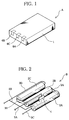
- FIGS. 1 and 2 show an example of the battery pack.
- FIG. 1 is a perspective view showing an outline of the battery pack.
- This battery pack A is composed of a battery group (mentioned later) stored in a shell 1 that is formed of a material such as a polycarbonate resin or polycarbonate/acrylonitrile-butadiene-styrene resin.
- a positive terminal 6A and a negative terminal 6B are exposed from the shell 1.
- a signal fetch terminal 6C for a built-in thermistor for the temperature control of the battery group, for example.
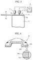
- FIG. 2 is a perspective view schematically showing a battery group B.
- the battery group B includes three cylindrical batteries 2A, 2B and 2C that are connected in series with one another. More specifically, the bottom (negative terminal) of the battery 2A and the positive terminal of the battery 2B are connected by means of a lead member 3A, while the bottom (negative terminal) of the battery 2B and the positive terminal of the battery 2C are connected by means of a lead member 3B. One end of a lead member 3C is connected to the positive terminal of the battery 2A, and the other end to the positive terminal 6A of the battery pack A. One end of a lead member 3D is connected to the bottom (negative terminal) of the battery 2C, and the other end to the negative terminal 6B of the battery pack A.
- a thermistor 4 is interposed between the batteries 2A and 2B, and two signal lines 5A and 5B are led out of the thermistor 4.
- the one signal line 5A is connected to the signal fetch terminal 6C of the battery pack A, and the other signal line 5B to the lead member 3D.
- insulating members are interposed as required between the batteries, between the batteries and the thermistor, etc. lest the batteries and the thermistor be shorted.
- Secondary batteries such as nickel-cadmium secondary batteries, nickel-metal-hydride secondary batteries, lithium-ion secondary batteries, are frequently used as the batteries that constitute the battery group B.
- each of these secondary batteries is constructed so that a specific power generating element is stored together with a prescribed electrolyte solution in a battery container, which is composed of an open-topped battery can and a cover member closing the top opening of the can.
- the battery can is formed of an Ni-plated steel sheet. It is obtained by shaping a sheet of soft steel, such as very-low-carbon steel, into a specific bottomed can by plastic deformation and forming an Ni layer of a desired thickness on the surface of the resulting structure by Ni-plating for the purpose of rustproofing.
- the cover member is obtained in like manner.
- each of the lead members that constitute the battery group B is formed of a small strip of Ni or, like the battery container, is formed of an Ni-plated steel sheet.
- the following parallel resistance welding method is generally applied to the connection between the batteries and the lead members for the manufacture of the battery group B.
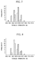
- a lead member 3 to be welded is put on a surface 2a (bottom surface as illustrated) of a battery container 2, as shown in FIG. 3.
- Two welding electrodes 7, each having a small-diameter distal end 7a, are arranged parallel to each other with a given space between them on a surface 3a of the lead member 3.
- a predetermined pressure loading from the welding electrodes 7 is applied to the lead member 3 so that a back surface 3b of the member 3 and the surface 2a of the battery container 2 are intimately in contact with each other.
- a welding current of a given value is supplied from a power source 8.
- the welding current is applied to the lead member 3 through one welding electrode.
- a part of the welding current is fed back to the power source 8 through the lead member 3 and the other welding electrode.
- the remaining part is applied to the region right under the distal end 7a of the one welding electrode and the surrounding area, and then flows across the thickness of the lead member 3 to reach the surface 2a of the battery container 2. Thereafter, the remaining current passes through the battery container 2, flows in the thickness direction of the lead member 3 around the region right under the distal end 7a of the other welding electrode, and is fed back to the power source through the other welding electrode.
- the respective surfaces of the lead member and the battery container are flat surfaces. Microscopically, however, they are complicated irregular surfaces. When the lead member is put on the surface of the battery container, therefore, these two members are not uniformly in contact with each other. More specifically, infinitesimal projections on the back surface 3b of the lead member and the surface 2a of the battery container 2 are only in contact with each other's surface. The formation of nuggets advances as current flows through the resulting infinitesimal contact portions to generate Joule heat therein.
- the welding behavior is complicated due to the influence of fine deformation of the lead member 3, which is caused as the welding electrodes 7 are pressed against the lead member 3, upon the contact state.
- the battery container and the lead member are formed of a Ni-plated steel sheet, the following problems are believed to arise if they are welded by the parallel resistance welding method.
- weld strength is not very high, then welded joints on a battery pack that is incorporated in an electric or electronic device to be actually used will possibly be broken by impact to ruin the function of the device in case the device is dropped, for example.
- weld strength varies, moreover, it can be supposed to lower the reliability of welding of welded structures of manufactured batteries and lead members, in consideration of the fact that the welding operation is usually continuously performed in a production line.
- the generated Joule heat is intensified by setting the supplied current at a high value or lengthening the conduction time. If this is done, however, the welding electrodes sometimes may be fused to the surface of the lead member, thereby preventing composition of smooth welding processes. In some cases, furthermore, generation of excessive heat may results in production of melt dust of the metal material that constitutes the surface of the battery container and the lead member, thus lowering the weld strength, on the contrary.
- An object of the present invention is to provide a battery and a lead member, designed so that high strength of weld between a battery container and the lead member can be maintained with less variation despite lower current supply thereto when the lead member is welded to the outer surface of the battery container by the parallel resistance welding method.
- Another object of the invention is to provide a battery and a lead member, which require no high current supply for welding, so that welding electrodes cannot be easily fused to the lead member, and smooth welding processes can be composed without entailing production of melt dust.
- Still another object of the invention is to provide a high-reliability battery pack that cannot be easily broken by external force such as impact.
- a battery comprising a battery container and a layer of an Ni-based alloy covering a part or the whole of the outer surface of the battery container.
- a lead member for battery connection which is welded to the outer surface of a battery by the parallel resistance welding method, the lead member comprising a substrate and an Ni-Sn alloy layer formed at least on that surface of the substrate which is welded to the outer surface of the battery.
- a battery pack comprising a group of the aforesaid batteries according to the invention connected to one another by means of lead members for battery connection by the parallel resistance welding method and a shell storing the group of the batteries therein, or a battery pack comprising a group of batteries connected to one another by means of the aforesaid lead members for battery connection according to the invention by the parallel resistance welding method and a shell storing the group of the batteries therein, or a battery pack comprising a group of the aforesaid batteries according to the invention connected to one another by means of the aforesaid lead members for battery connection according to the invention by the parallel resistance welding method and a shell storing the group of the batteries therein.
- a battery according to the present invention will be described first.
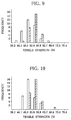
- FIG. 4 is a cutaway sectional view showing an example of a battery container of the battery of the invention. Referring to FIG. 4, there is shown a cover member 21 that serves also as a positive terminal.
- the cover member 21 includes a substrate 21a, which is a sheet of soft steel such as very-low-carbon steel, and a layer 21b of an Ni-based alloy (mentioned later).
- the member 21 is obtained by forming the substrate 21a into the shape shown in FIG. 4 by plastic deformation and covering its surface with the layer 21b.
- the layer 21b may be formed covering the whole surface of the substrate 21a or partially covering at least those portions where a lead member, a mating member, is to be welded.
- the cover member is shown as an example of the battery container in FIG. 4, the battery container of the battery according to the present invention is not limited to the cover member, and may alternatively be a battery can that mates with the cover member and stores a power generating element and an alkaline electrolyte solution therein.
- the layer 21b should preferably be formed of an Ni-Fe alloy, it must only be formed of one of Ni-based alloys including an Ni-Co alloy, Ni-Zn alloy, Ni-Fe-Co alloy, etc.
- the layer 21b is formed by electroplating the surface of the substrate 21a.
- Ni-based alloys that are formed by electroplating may be composed of a single-phase solid solution of Fe, Co, Zn and other elements in a crystal lattice of Ni or a combination of a plurality of phases. In general, its specific resistance is higher than that of simple Ni or any other simple element. If the aforementioned parallel resistance welding method is applied to a battery container that has these Ni-based alloy layers, a smaller current flow than in the conventional case enables the formation of stable nuggets, thereby ensuring improved weld strength. One of reasons for this effect is the level of the electric resistance of the layer formed of the aforesaid Ni-based alloy. Another possible factor is the change of the mechanical properties of the materials.
- the Ni-Fe alloy is a particularly effective material because it enables a small current to improve the weld strength.
- the Fe content is restricted to 50% by atomic percentage or to 45% in particular.
- This restriction of the Fe content can be easily achieved by adjusting the concentration of an Fe source in a plating bath for electroplating, for example.
- the Co content should preferably be restricted to 5 to 50% by atomic percentage.
- the Zn content should preferably be restricted to 5 to 30% by atomic percentage.
- the Fe and Co contents should preferably be restricted to more than 0 to less than 50% by atomic percentage and to 5 to 50% by atomic percentage, respectively. Even in this case, however, the sum of the Fe and Co contents is restricted to 50% or less by atomic percentage.
- the thickness of the layer 21b is restricted to 5 ⁇ m or less. If the thickness exceeds 5 ⁇ m, the variation of the strength of weld on the lead member increases.
- the layer 21b is formed of the Ni-Fe alloy, moreover, its thickness should preferably be restricted to 4.5 ⁇ m or less. The reason for this, though not evident, is that the strength of weld on the lead member substantially varies if the layer thickness exceeds 4.5 ⁇ m.
- the thickness of the layer 21b can be easily adjusted by regulating the time and current density for electroplating, for example.
- FIG. 5 is a sectional view showing an example of the lead member.
- the lead member 31 is composed of a substrate 31a and an Ni-Sn alloy layer 31c covering its surface or of the substrate 31a, an under layer 31b covering the surface of the substrate 31a, and an Ni-Sn alloy layer 31c covering the surface of the layer 31b. It is to be understood that the lead member 31 is electrically conductive in either case.
- the substrate 31a ensures the strength of the whole lead member and functions also as a passage through which welding current flows during actual use of the lead member.
- the substrate 31a may be formed of any material that has appropriate strength and electrical conductivity and can be plated.
- low-carbon steel, Ni, etc. may be used for this purpose. Low-carbon steel is preferred because it is easily available and low-priced.
- an under layer 31b may be provided as an intermediate layer in order to prevent the Ni-Sn alloy layer 31c on the substrate 31a from peeling off from the surface of the substrate 31a and to ensure stable plating with the Ni-Sn alloy.
- the under layer 31b is formed of a material that contains an Ni component, in consideration of the Ni-Sn alloy layer formed thereon.
- An Ni layer, Ni-Fe alloy layer, etc. may be used for this purpose.
- a Cu layer, Cu-Sn alloy layer, etc. may be used despite the absence of Ni.
- the under layer 31b can be easily formed by applying a conventional film forming method, such as electroplating, vacuum evaporation, sputtering, etc., to the surface of the substrate 31a.
- a conventional film forming method such as electroplating, vacuum evaporation, sputtering, etc.
- the electroplating method has an advantage over the others in film quality, film forming cost, and productivity.
- the thickness of the layer 31b is adjusted to 0.2 to 10 ⁇ m.
- the intermediate layer 31b is not essential.
- the Ni-Sn alloy layer 31c is provided in order to make contact with the surface of the battery container, a mating layer, at the time of resistance welding, thereby generating intensive Joule heat in the contact interface to facilitate the formation of stable nuggets.
- the layer 31c serves to ensure stable and high strength of weld between the lead member and the battery container.
- the Ni-Sn alloy that constitutes the layer 31c consists mainly of Ni and Sn.
- the composition ratios of Ni and Sn are suitably selected in consideration of the melting point and specific resistance of the alloy. If the composition ratio of Sn is too high, the strength of weld on the battery container lowers for some unknown reasons. If the composition ratio of Sn is too low, adding the welding strength problem described above, the layer 31c is unduly brittle, and the film forming cost is high. Preferably, therefore, the composition ratio of Sn is restricted to 40 to 75 wt%.
- the Ni-Sn alloy layer 31c can be formed by applying a conventional film forming method, such as electroplating, vacuum evaporation, sputtering, etc., to the surface of the substrate 31a or the under layer 31b.
- a conventional film forming method such as electroplating, vacuum evaporation, sputtering, etc.
- the electroplating method has an advantage over the others in being capable of more easily ensuring good film properties, as well as in film forming cost and productivity.
- Ni-Sn alloy layer 31c by the electroplating method, it is necessary only that the surface of the substrate 31a or the under layer 31b be electroplated under given conditions by using a plating bath that contains an Ni source, such as nickel chloride (NiCl 2 ⁇ 6H 2 O), and an Sn source, such as stannous chloride (SnCl 2 ⁇ 2H 2 O), in a predetermined concentration ratio.
- Ni source such as nickel chloride (NiCl 2 ⁇ 6H 2 O)
- Sn source such as stannous chloride (SnCl 2 ⁇ 2H 2 O
- the thickness of the layer 31c is adjusted to 0.1 to 10 ⁇ m, and most preferably to 0.2 to 8 ⁇ m.
- the battery pack according to the invention differs from the battery pack of the conventional structure shown in FIGS. 1 and 2 only in that the batteries constituting the battery group and/or the lead member is replaced by batteries and/or a lead member according to the invention.
- the strength of weld between the battery container and the lead member is higher than in the case of the conventional battery pack that uses the battery group of which the battery container and the lead member are formed of an Ni-plated steel sheet each.
- the battery pack according to the invention is a highly reliable structure that cannot be easily broken by impact or any other external force.
- the battery pack of the invention that contains therein a battery group manufactured by using the batteries and the lead member according to the invention is so reliable that it can serve as a useful driving Power source for an electric vehicle, motor-assisted bicycle, etc.
- Battery cans and covers for AA-size batteries were prepared.
- a soft steel sheet was used as the material of any of these members.
- Plating baths for Ni-Fe alloys were prepared containing ferrous chloride, nickel chloride, and calcium chloride.
- various plating baths with different Fe concentrations were prepared with the ferrous chloride concentration varied from 210 to 380 g/L, nickel chloride concentration from 30 to 80 g/L, and calcium chloride from 150 to 180 g/L.
- Thiourea was added as required at the concentration of 1 g/L or less.
- the battery cans and covers were electroplated in these plating baths, whereupon Ni-Fe alloy layers with different Fe contents were formed on the respective surfaces of the battery cans and covers.
- Appropriate plating conditions were selected including pHs of 0.9 to 1.5, bath temperatures of 60 to 90°C, and current densities of 3 to 5 A/dm 2 .
- the plating time was adjusted so that the layer thickness was 3 ⁇ m.
- AA-size nickel-metal-hydride secondary batteries were assembled with use of the battery cans and covers obtained in this manner.
- a conventional lead member formed of an Ni-plated soft steel sheet 0.15 mm thick and 5 mm wide, was put on the bottom surface of each battery, and the battery and the lead member were welded under the conditions shown in Table 1 by the parallel resistance welding method, as shown in FIG. 3.
- the pressure loading from welding electrodes applied to each lead member was 22 newtons (N).
- the value of this pressure loading is the sum of forces applied to the two welding electrodes.
- the forces applied individually to the electrodes are set at substantially equal values (about 11 N each).
- a measurement test for weld strength was conducted in the manner shown in FIG. 6. It is a test in which one end 3c of a lead member 3 welded to the bottom surface of a battery container 21 of a battery according to the invention is held by means of a chuck 9, and the chuck 9 is pulled up by means of a tension tester 10 to strip off the lead member 3. In doing this, the lead member 3 was pulled up in a direction substantially parallel to the central axis of the container 21 so that the force of the tester 10 to pull the chuck 9 increased at a substantially fixed rate. The pulling force (tensile strength) with which the lead member 3 was completely separated from the bottom surface of the container 21 was defined as the weld strength. Table 1 collectively shows mean values for 30 battery containers as the results of the test.
- Comparative Example 1 represents the case where the battery container and the lead member are formed of an Ni-plated steel sheet each. Comparative Example 1 Example No. 1 2 3 4 5 6 Fe content of layer (Ni-Fe alloy) (% by atomic percentage) 0 (layer of Ni only) 5 10 20 30 40 50 Weld strength (N) Welding current during welding operation: 1.4kA 50.5 53.5 60.3 63.7 64.1 63.9 62.8 1.5kA 51.9 55.5 63.9 67.6 65.1 68.8 66.3 1.6kA 61.0 61.1 63.9 68.9 66.3 70.0 67.5
- Table 1 reveals the following facts.
- Layers of an Ni-Fe alloy with the thicknesses shown in Table 2 were formed on battery containers for varied plating times with use of a plating bath that is adjusted in composition so that the Fe contents of the layers were 20% by atomic percentage. Then, 30 batteries were assembled using the individual battery containers, and the aforesaid lead member (formed of a Ni-plated steel sheet) was put on the bottom surface of each battery container. The lead member and the battery container were subjected to resistance welding in a manner such that they are supplied with a welding current of 1.5 kA under a pressure loading of 22 N from the welding electrodes.
- This pressure loading is the sum of forces applied to the two welded electrodes.
- the forces applied individually to the electrodes are set at substantially equal values.
- Example No. 7 8 9 10 11 Layer thickness ( ⁇ m) 2.5 3 4 5 6 Weld strength (N) Mean value (n 30) 66.3 67.6 65.1 56.7 49.5 Maximum value 72.3 73.1 75.3 71.6 68.4 Minimum value 59.8 58.3 56.9 53.8 48.1
- the weld strength becomes inclined to lower if the layer thickness exceeds 5 ⁇ m. As the layer thickness increases, moreover, the weld strength tends to vary. Preferably, therefore, the layer thickness is adjusted to 5 ⁇ m or less. In the case where the thickness is about 3 ⁇ m, in particular, the weld strength is high and its variation is very small, so that stable quality control can be ensured.
- a plated steel sheet of 0.3-mm thickness was prepared by coating the surface of a soft steel sheet of 0.3-mm thickness with an Ni-Fe alloy layer of 2.0- ⁇ m thickness formed of an Ni-25% Fe alloy, and it was molded into battery covers by plastic deformation.
- a soft steel lead member formed of an Ni-plated steel sheet of 0.15-mm thickness, having an Ni layer of 2.0- ⁇ m thickness thereon, was pressed against the surface of each cover under a pressure loading of 22 N, resistance welding was carried out with the welding currents shown in Table 3 for about 5 ms.
- each battery according to the invention a small welding current can produce high weld strength although the lead member is formed of the conventional Ni-plated steel sheet.
- Battery cans and covers for AA-size batteries were prepared.
- a soft steel sheet was used as the material of any of these members.
- a plating bath for an Ni-Co alloy was prepared containing 250 g/L of nickel chloride, 15 g/L of cobalt chloride, and 15 g/L of boric acid.
- the battery cans and covers were electroplated in this plating bath under conditions including a pH of 3, current density of 1.5 A/dm 2 , and bath temperature of 20°C, whereupon an Ni-15% Co alloy layer of 3- ⁇ m thickness was formed on each of the respective surfaces of the battery cans and covers.
- a lead member formed of an Ni-plated soft steel sheet with 0.15 mm thick and 5 mm wide, was put on the bottom surface of each battery, and was subjected to resistance welding under the same conditions as in Examples 1 to 6.
- the weld strength was 62.5 N (mean value) for the welding current of 1.4 kA, 63.9 N (mean value) for 1.5 kA, and 65.1 N (mean value) for 1.6 kA.
- a plating bath was prepared containing 220 g/L of nickel sulfate, 30 g/L of nickel chloride, 40 g/L of nickel formate, 4.8 g/L of cobalt sulfate, 0.8 g/L of ammonium sulfate, 2 g/L of formaldehyde, and 28 g/L of boric acid.
- the battery cans and covers used in Example 13 were electroplated in this plating bath under conditions including a pH of 3.7, current density of 5 A/dm 2 , and bath temperature of 65°C, whereupon an Ni-7% Co alloy layer of 3- ⁇ m thickness was formed on each of the respective surfaces of the battery cans and covers.
- a lead member formed of an Ni-plated soft steel sheet 0.15 mm thick and 5 mm wide, was put on the bottom surface of each battery, and was subjected to resistance welding under the same conditions as in Examples 1 to 6.
- the weld strength was 62.3 N (mean value) for the welding current of 1.4 kA, 61.7 N (mean value) for 1.5 kA, and 64.9 N (mean value) for 1.6 kA.
- a low-carbon steel sheet (carbon concentration: 0.08%), 0.15 mm thick, 5.9 mm wide, and 30 mm long, was prepared as a substrate of a lead member.
- a plating bath was prepared containing 240 g/L of nickel sulfate, 45 g/L of nickel chloride, 30 g/L of boric acid, and 1.5 g/L of saccharin, and an Ni layer of 3- ⁇ m thickness was formed as an under layer on the whole surface of the substrate under conditions including a pH of 4.0, bath temperature of 45°C, and current density of 4 A/dm 2 .
- a plating bath was prepared containing 300 g/L of nickel chloride, 50 g/L of stannous chloride, 35 g/L of ammonium hydrofluorate, and 25 g/L of sodium fluoride.
- One side of the Ni layer was masked and immersed in the plating bath, whereupon an Ni-Sn alloy layer of 0.3- ⁇ m thickness was formed on the one side of the Ni layer under conditions including a bath temperature of 65°C and current density of 2.5 A/dm 2 .
- the lead member 31 according to the invention was manufactured having the profile shown in FIG. 5.
- the Ni-Sn alloy contained 35 wt% of Ni and 65 wt% of Sn.
- An under layer having an Ni surface was prepared as Comparative Example 3 without forming the Ni-Sn alloy layer thereon.
- AAA-size nickel-metal-hydride batteries (batteries of Comparative Example) were prepared having a battery container obtained by forming an Ni layer of 3 to 3.5-mm thickness on the surface of a low-carbon steel sheet (carbon concentration: 0.04%) of 0.3-mm thickness.
- the aforesaid lead member was put on the bottom surface of each battery, a pressure loading of 22 N (sum of forces on two welding electrodes) is applied by means of welding electrodes, and the lead member 31 was welded to the battery container with welding currents of 1.6 kA and 1.7 kA by the parallel resistance welding method, as shown in FIG. 3.
- the forces applied individually to the two electrodes are set at substantially equal values.
- FIG. 7 shows the results obtained when the welding current was 1.6 kA
- FIG. 8 shows the results obtained when the welding current was 1.7 kA.
- hatched bars represent the case where the lead member 31 according to the invention was used
- blank bars represent the case where the lead member of Comparative Example 3 was used.
- a lead member 31 was manufactured having the same profile as that of Example 15 except that its under layer was a Cu layer of 0.8- ⁇ m thickness formed by using a plating bath of pyrophosphoric acid and that its Ni-Sn alloy layer is an Ni-65% Sn alloy layer of 0.6- ⁇ m thickness formed under the plating conditions of Example 15.
- Example 15 Thirty nickel-metal-hydride batteries used in Example 15 were prepared, and the lead member was resistance-welded to each of the batteries in the same manner as in Example 15. Thereafter, the weld strength was measured in the same manner as in Example 15.
- FIGS. 9 and 10 show the results of the measurement.
- FIG. 9 shows the results obtained when the welding current was 1.6 kA
- FIG. 10 shows the results obtained when the welding current was 1.7 kA.
- hatched bars represent the case where the lead member 31 according to the invention was used
- blank bars represent the case where the lead member of Comparative Example 3 was used.
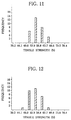
- a battery having an Ni-Fe alloy layer of 3.0- ⁇ m thickness formed of an Ni-20% Fe alloy, on its container surface, and the lead member of Example 15 were resistance-welded under the same conditions as in Example 15 by the method used in the cases of Examples 1 to 6, and the weld strength was measured.
- FIGS. 11 and 12 show the results of the measurement.
- FIG. 11 shows the results obtained when the welding current was 1.6 kA
- FIG. 12 shows the results obtained when the welding current was 1.7 kA.
Landscapes
- Chemical & Material Sciences (AREA)
- Chemical Kinetics & Catalysis (AREA)
- Electrochemistry (AREA)
- General Chemical & Material Sciences (AREA)
- Engineering & Computer Science (AREA)
- Materials Engineering (AREA)
- Mechanical Engineering (AREA)
- Metallurgy (AREA)
- Organic Chemistry (AREA)
- Inorganic Chemistry (AREA)
- Connection Of Batteries Or Terminals (AREA)
- Sealing Battery Cases Or Jackets (AREA)
Applications Claiming Priority (4)
| Application Number | Priority Date | Filing Date | Title |
|---|---|---|---|
| JP10068908A JPH11265692A (ja) | 1998-03-18 | 1998-03-18 | 電池容器 |
| JP06890998A JP3885342B2 (ja) | 1998-03-18 | 1998-03-18 | 電池用リード材およびそれを用いた電池パック |
| JP6890898 | 1998-03-18 | ||
| JP6890998 | 1998-03-18 |
Publications (2)
| Publication Number | Publication Date |
|---|---|
| EP0944123A1 true EP0944123A1 (de) | 1999-09-22 |
| EP0944123B1 EP0944123B1 (de) | 2002-01-16 |
Family
ID=26410098
Family Applications (1)
| Application Number | Title | Priority Date | Filing Date |
|---|---|---|---|
| EP99104040A Expired - Lifetime EP0944123B1 (de) | 1998-03-18 | 1999-03-16 | Batterie, Stromanschlussfahne zun Verbinden von Batterien, und daraus aufgebautes Batteriepack |
Country Status (5)
| Country | Link |
|---|---|
| US (1) | US6562493B2 (de) |
| EP (1) | EP0944123B1 (de) |
| KR (1) | KR100345182B1 (de) |
| DE (1) | DE69900657T2 (de) |
| TW (1) | TW502467B (de) |
Cited By (5)
| Publication number | Priority date | Publication date | Assignee | Title |
|---|---|---|---|---|
| US6270922B1 (en) * | 1996-09-03 | 2001-08-07 | Toyo Kohan Co., Ltd. | Surface-treated steel plate for battery case, battery case and battery using the case |
| WO2005001986A3 (en) * | 2003-06-13 | 2005-03-17 | Gillette Co | Fuel cartridge interconnect for portable fuel cells |
| EP1450422A4 (de) * | 2001-11-27 | 2008-04-30 | Matsushita Electric Industrial Co Ltd | Batterieverbindungsstruktur, batteriemodul und batteriepack |
| US7482091B2 (en) | 2003-07-09 | 2009-01-27 | The Gillette Company | Fuel cartridge interconnect for portable fuel cells |
| CN110690403A (zh) * | 2015-09-11 | 2020-01-14 | 日立金属株式会社 | 电池用引线部件和电池用引线部件的制造方法 |
Families Citing this family (24)
| Publication number | Priority date | Publication date | Assignee | Title |
|---|---|---|---|---|
| USD474149S1 (en) | 2002-02-13 | 2003-05-06 | Nikon Corporation | Storage battery |
| JP3742422B1 (ja) * | 2005-03-17 | 2006-02-01 | 日立マクセル株式会社 | 扁平形電池 |
| KR100659852B1 (ko) * | 2005-04-25 | 2006-12-19 | 삼성에스디아이 주식회사 | 캔형 이차 전지 |
| US20070099073A1 (en) * | 2005-10-31 | 2007-05-03 | White Daniel J | Cell connection straps for battery cells of a battery pack |
| US20110008655A1 (en) * | 2006-10-20 | 2011-01-13 | White Daniel J | Cell connection straps for battery cells of a battery pack |
| KR20080045305A (ko) * | 2006-11-20 | 2008-05-23 | 주식회사 엘지화학 | 디바이스에 도전성 부재를 결합시키는 방법 |
| BRPI0813288A2 (pt) * | 2007-06-22 | 2014-12-30 | Boston Power Inc | Dispositivo de interrupção de corrente, bateria, bateria de íons de lítio, métodos para manufaturar um dispositivo de interrupção de corrente, uma bateria, e uma bateria de íons de lítio. |
| US8780507B2 (en) * | 2007-12-28 | 2014-07-15 | HGST Netherlands B.V. | Read transducer and magnetic storage system implementing same |
| DE102008010823A1 (de) * | 2008-02-23 | 2009-08-27 | Daimler Ag | Batterie mit mehreren einen Zellverbund bildenden Flachzellen |
| US9246140B2 (en) * | 2009-07-09 | 2016-01-26 | Samsung Sdi Co., Ltd. | Rechargeable battery with a cap assembly having a first tab located outside of the case |
| US8877361B2 (en) * | 2009-09-01 | 2014-11-04 | Samsung Sdi Co., Ltd. | Rechargeable battery |
| CN101771142B (zh) * | 2010-02-10 | 2012-09-19 | 力佳电源科技(深圳)有限公司 | 一种软包锂电池极耳材料及其电镀和应用方法 |
| WO2011099160A1 (ja) * | 2010-02-15 | 2011-08-18 | 株式会社Neomaxマテリアル | リード用クラッド材およびリード用クラッド材の溶接方法 |
| JP2011171158A (ja) * | 2010-02-19 | 2011-09-01 | Panasonic Corp | アルカリ電池 |
| KR101127613B1 (ko) | 2010-05-13 | 2012-03-22 | 삼성에스디아이 주식회사 | 배터리 팩 |
| US9478774B2 (en) * | 2010-12-02 | 2016-10-25 | Samsung Sdi Co., Ltd. | Rechargeable battery |
| WO2012153728A1 (ja) * | 2011-05-10 | 2012-11-15 | Jx日鉱日石金属株式会社 | Niめっき金属板、溶接構造体、及び電池用材料の製造方法 |
| US20120315523A1 (en) * | 2011-06-09 | 2012-12-13 | Michael Pozin | Electrochemical cells with improved spiral-wound electrode assembly |
| KR101274806B1 (ko) | 2011-07-26 | 2013-06-13 | 로베르트 보쉬 게엠베하 | 이차 전지 |
| US9634299B2 (en) | 2011-09-06 | 2017-04-25 | Samsung Sdi Co., Ltd. | Rechargeable battery |
| KR101683210B1 (ko) | 2011-11-17 | 2016-12-07 | 삼성에스디아이 주식회사 | 이차 전지 |
| USD799425S1 (en) * | 2014-01-30 | 2017-10-10 | Nikon Corporation | Battery |
| KR102251329B1 (ko) * | 2014-06-17 | 2021-05-12 | 삼성에스디아이 주식회사 | 이차 전지 |
| KR102814281B1 (ko) * | 2019-03-29 | 2025-05-29 | 도요 고한 가부시키가이샤 | 알칼리 이차전지용 표면 처리판 및 그 제조 방법 |
Citations (7)
| Publication number | Priority date | Publication date | Assignee | Title |
|---|---|---|---|---|
| EP0494504A2 (de) * | 1991-01-08 | 1992-07-15 | Matsushita Electric Industrial Co., Ltd. | Alkalische Speicherbatterie |
| JPH04264358A (ja) * | 1991-02-18 | 1992-09-21 | Toshiba Battery Co Ltd | 電池用極板の製造法 |
| EP0607675A1 (de) * | 1992-12-22 | 1994-07-27 | Honda Giken Kogyo Kabushiki Kaisha | Batterie mit rostschützender Struktur |
| EP0725453A1 (de) * | 1993-10-22 | 1996-08-07 | TOYO KOHAN Co., Ltd | Oberflächenbehandeltes stahlblech für batteriegehäuse und batteriegehäuse |
| EP0807984A1 (de) * | 1996-05-17 | 1997-11-19 | Katayama Special Industries, Ltd. | Blech für die Formgebung eines Batteriebehälters und daraus erhältlicher Batteriebecher |
| EP0809307A2 (de) * | 1996-05-21 | 1997-11-26 | Katayama Special Industries, Ltd. | Blech für die Formgebung vom Batteriegehäuse und Batteriegehäuse |
| EP0822266A1 (de) * | 1996-02-08 | 1998-02-04 | Nkk Corporation | Stahlblech mit hervorragender formbarkeit, weiterverarbeitungsverprödungswiderstand und rostbeständigkeit für zweiteiliges batteriegehäuse |
Family Cites Families (5)
| Publication number | Priority date | Publication date | Assignee | Title |
|---|---|---|---|---|
| US3607439A (en) * | 1969-07-02 | 1971-09-21 | Olin Mathieson | Minature battery or power cell containers |
| US4431713A (en) * | 1982-04-15 | 1984-02-14 | Duracell Inc. | Method for adapting high voltage cells or batteries for lower volt rated applications |
| US5761792A (en) * | 1990-11-27 | 1998-06-09 | Alexander Manufacturing Corporation | Method for making a battery pack |
| US5197889A (en) * | 1992-02-03 | 1993-03-30 | Motorola, Inc. | Electrical contact for battery package or similar device |
| US6071557A (en) * | 1997-09-30 | 2000-06-06 | Matsushita Electric Industrial Co., Ltd. | Cell with a cladding material including a stainless-steel plate and an aluminum plate |
-
1999
- 1999-03-06 TW TW088103478A patent/TW502467B/zh not_active IP Right Cessation
- 1999-03-16 EP EP99104040A patent/EP0944123B1/de not_active Expired - Lifetime
- 1999-03-16 DE DE69900657T patent/DE69900657T2/de not_active Expired - Lifetime
- 1999-03-17 KR KR1019990009008A patent/KR100345182B1/ko not_active Expired - Fee Related
- 1999-03-18 US US09/271,445 patent/US6562493B2/en not_active Expired - Fee Related
Patent Citations (7)
| Publication number | Priority date | Publication date | Assignee | Title |
|---|---|---|---|---|
| EP0494504A2 (de) * | 1991-01-08 | 1992-07-15 | Matsushita Electric Industrial Co., Ltd. | Alkalische Speicherbatterie |
| JPH04264358A (ja) * | 1991-02-18 | 1992-09-21 | Toshiba Battery Co Ltd | 電池用極板の製造法 |
| EP0607675A1 (de) * | 1992-12-22 | 1994-07-27 | Honda Giken Kogyo Kabushiki Kaisha | Batterie mit rostschützender Struktur |
| EP0725453A1 (de) * | 1993-10-22 | 1996-08-07 | TOYO KOHAN Co., Ltd | Oberflächenbehandeltes stahlblech für batteriegehäuse und batteriegehäuse |
| EP0822266A1 (de) * | 1996-02-08 | 1998-02-04 | Nkk Corporation | Stahlblech mit hervorragender formbarkeit, weiterverarbeitungsverprödungswiderstand und rostbeständigkeit für zweiteiliges batteriegehäuse |
| EP0807984A1 (de) * | 1996-05-17 | 1997-11-19 | Katayama Special Industries, Ltd. | Blech für die Formgebung eines Batteriebehälters und daraus erhältlicher Batteriebecher |
| EP0809307A2 (de) * | 1996-05-21 | 1997-11-26 | Katayama Special Industries, Ltd. | Blech für die Formgebung vom Batteriegehäuse und Batteriegehäuse |
Non-Patent Citations (1)
| Title |
|---|
| PATENT ABSTRACTS OF JAPAN vol. 017, no. 050 (E - 1314) 29 January 1993 (1993-01-29) * |
Cited By (7)
| Publication number | Priority date | Publication date | Assignee | Title |
|---|---|---|---|---|
| US6270922B1 (en) * | 1996-09-03 | 2001-08-07 | Toyo Kohan Co., Ltd. | Surface-treated steel plate for battery case, battery case and battery using the case |
| EP1450422A4 (de) * | 2001-11-27 | 2008-04-30 | Matsushita Electric Industrial Co Ltd | Batterieverbindungsstruktur, batteriemodul und batteriepack |
| WO2005001986A3 (en) * | 2003-06-13 | 2005-03-17 | Gillette Co | Fuel cartridge interconnect for portable fuel cells |
| CN100446340C (zh) * | 2003-06-13 | 2008-12-24 | 吉莱特公司 | 用于便携式燃料电池的燃料盒互连 |
| US7482091B2 (en) | 2003-07-09 | 2009-01-27 | The Gillette Company | Fuel cartridge interconnect for portable fuel cells |
| US7862926B2 (en) | 2003-07-09 | 2011-01-04 | The Gillette Company | Fuel cartridge interconnect for portable fuel cells |
| CN110690403A (zh) * | 2015-09-11 | 2020-01-14 | 日立金属株式会社 | 电池用引线部件和电池用引线部件的制造方法 |
Also Published As
| Publication number | Publication date |
|---|---|
| KR19990077983A (ko) | 1999-10-25 |
| US20020012838A1 (en) | 2002-01-31 |
| US6562493B2 (en) | 2003-05-13 |
| DE69900657D1 (de) | 2002-02-21 |
| KR100345182B1 (ko) | 2002-07-24 |
| EP0944123B1 (de) | 2002-01-16 |
| TW502467B (en) | 2002-09-11 |
| HK1024786A1 (en) | 2000-10-20 |
| DE69900657T2 (de) | 2002-08-14 |
Similar Documents
| Publication | Publication Date | Title |
|---|---|---|
| EP0944123B1 (de) | Batterie, Stromanschlussfahne zun Verbinden von Batterien, und daraus aufgebautes Batteriepack | |
| US8334066B2 (en) | Secondary battery and manufacturing method thereof | |
| US6379839B1 (en) | Battery having welded lead plate | |
| EP0560579B1 (de) | Quecksilberfreie Zink-Luft-Miniatur-Zelle | |
| EP0725453B1 (de) | Oberflächenbehandeltes stahlblech für batteriegehäuse und batteriegehäuse | |
| US6316148B1 (en) | Foil-encapsulated, lightweight, high energy electrodes for lead-acid batteries | |
| KR100870334B1 (ko) | 접속 부품용 도전 재료 및 그의 제조방법 | |
| US6485863B2 (en) | Battery container with surface treated steel sheet | |
| JP2000106170A (ja) | 接続板 | |
| HK1000492B (en) | Mercury free miniature zinc-air cells | |
| US5223354A (en) | Lead-acid battery plate and its manufacturing method | |
| US11108171B2 (en) | Terminal, and terminal-attached cable and wire harness with the terminal | |
| US20180212350A1 (en) | Terminal plating material, and terminal, terminal-equipped electric wire and wire harness using the same | |
| EP0160222A2 (de) | Nickel/Indium-Legierung für die Herstellung eines hermetisch verschlossenen Gehäuses für Halbleiteranordnungen und andere elektronische Anordnungen | |
| US3933524A (en) | Antimony plating of lead-acid storage batteries grids | |
| JPH09330629A (ja) | 電気接点材料、及びその製造方法、及び前記電気接点材料を用いた操作スイッチ | |
| JPH07122246A (ja) | 電池ケース用表面処理鋼板および電池ケース | |
| HK1024786B (en) | Battery, lead member for battery connection, and battery pack using the same | |
| US20140134473A1 (en) | Electrical interconnect and method of assembling a rechargeable battery | |
| JP3885342B2 (ja) | 電池用リード材およびそれを用いた電池パック | |
| JP2007035650A (ja) | 電池容器の溶接方法 | |
| JPH11265692A (ja) | 電池容器 | |
| JP4437302B2 (ja) | 電池容器 | |
| JPS5913237Y2 (ja) | リ−ドスイツチ | |
| US20140134471A1 (en) | Electrical interconnect and method of assembling a rechargeable battery |
Legal Events
| Date | Code | Title | Description |
|---|---|---|---|
| PUAI | Public reference made under article 153(3) epc to a published international application that has entered the european phase |
Free format text: ORIGINAL CODE: 0009012 |
|
| AK | Designated contracting states |
Kind code of ref document: A1 Designated state(s): DE FR GB |
|
| AX | Request for extension of the european patent |
Free format text: AL;LT;LV;MK;RO;SI |
|
| 17P | Request for examination filed |
Effective date: 19991025 |
|
| AKX | Designation fees paid |
Free format text: DE FR GB |
|
| 17Q | First examination report despatched |
Effective date: 20000508 |
|
| GRAG | Despatch of communication of intention to grant |
Free format text: ORIGINAL CODE: EPIDOS AGRA |
|
| GRAG | Despatch of communication of intention to grant |
Free format text: ORIGINAL CODE: EPIDOS AGRA |
|
| GRAH | Despatch of communication of intention to grant a patent |
Free format text: ORIGINAL CODE: EPIDOS IGRA |
|
| GRAH | Despatch of communication of intention to grant a patent |
Free format text: ORIGINAL CODE: EPIDOS IGRA |
|
| GRAA | (expected) grant |
Free format text: ORIGINAL CODE: 0009210 |
|
| REG | Reference to a national code |
Ref country code: GB Ref legal event code: IF02 |
|
| AK | Designated contracting states |
Kind code of ref document: B1 Designated state(s): DE FR GB |
|
| REF | Corresponds to: |
Ref document number: 69900657 Country of ref document: DE Date of ref document: 20020221 |
|
| ET | Fr: translation filed | ||
| PLBE | No opposition filed within time limit |
Free format text: ORIGINAL CODE: 0009261 |
|
| STAA | Information on the status of an ep patent application or granted ep patent |
Free format text: STATUS: NO OPPOSITION FILED WITHIN TIME LIMIT |
|
| 26N | No opposition filed | ||
| PGFP | Annual fee paid to national office [announced via postgrant information from national office to epo] |
Ref country code: GB Payment date: 20130313 Year of fee payment: 15 Ref country code: DE Payment date: 20130314 Year of fee payment: 15 Ref country code: FR Payment date: 20130325 Year of fee payment: 15 |
|
| REG | Reference to a national code |
Ref country code: DE Ref legal event code: R119 Ref document number: 69900657 Country of ref document: DE |
|
| GBPC | Gb: european patent ceased through non-payment of renewal fee |
Effective date: 20140316 |
|
| REG | Reference to a national code |
Ref country code: FR Ref legal event code: ST Effective date: 20141128 |
|
| REG | Reference to a national code |
Ref country code: DE Ref legal event code: R119 Ref document number: 69900657 Country of ref document: DE Effective date: 20141001 |
|
| PG25 | Lapsed in a contracting state [announced via postgrant information from national office to epo] |
Ref country code: FR Free format text: LAPSE BECAUSE OF NON-PAYMENT OF DUE FEES Effective date: 20140331 Ref country code: GB Free format text: LAPSE BECAUSE OF NON-PAYMENT OF DUE FEES Effective date: 20140316 Ref country code: DE Free format text: LAPSE BECAUSE OF NON-PAYMENT OF DUE FEES Effective date: 20141001 |