EP0944240A2 - Système et procédé de transmission d'images, appareils de transmission et de réception d'images - Google Patents
Système et procédé de transmission d'images, appareils de transmission et de réception d'images Download PDFInfo
- Publication number
- EP0944240A2 EP0944240A2 EP99302128A EP99302128A EP0944240A2 EP 0944240 A2 EP0944240 A2 EP 0944240A2 EP 99302128 A EP99302128 A EP 99302128A EP 99302128 A EP99302128 A EP 99302128A EP 0944240 A2 EP0944240 A2 EP 0944240A2
- Authority
- EP
- European Patent Office
- Prior art keywords
- image
- transfer
- information
- images
- data
- Prior art date
- Legal status (The legal status is an assumption and is not a legal conclusion. Google has not performed a legal analysis and makes no representation as to the accuracy of the status listed.)
- Granted
Links
Images




Classifications
-
- H—ELECTRICITY
- H04—ELECTRIC COMMUNICATION TECHNIQUE
- H04N—PICTORIAL COMMUNICATION, e.g. TELEVISION
- H04N1/00—Scanning, transmission or reproduction of documents or the like, e.g. facsimile transmission; Details thereof
- H04N1/32—Circuits or arrangements for control or supervision between transmitter and receiver or between image input and image output device, e.g. between a still-image camera and its memory or between a still-image camera and a printer device
- H04N1/32101—Display, printing, storage or transmission of additional information, e.g. ID code, date and time or title
- H04N1/32106—Display, printing, storage or transmission of additional information, e.g. ID code, date and time or title separate from the image data, e.g. in a different computer file
- H04N1/32117—Display, printing, storage or transmission of additional information, e.g. ID code, date and time or title separate from the image data, e.g. in a different computer file in a separate transmission or protocol signal prior to or subsequent to the image data transmission, e.g. in digital identification signal [DIS], in non standard setup [NSS] or in non standard field [NSF]
-
- H—ELECTRICITY
- H04—ELECTRIC COMMUNICATION TECHNIQUE
- H04N—PICTORIAL COMMUNICATION, e.g. TELEVISION
- H04N1/00—Scanning, transmission or reproduction of documents or the like, e.g. facsimile transmission; Details thereof
- H04N1/32—Circuits or arrangements for control or supervision between transmitter and receiver or between image input and image output device, e.g. between a still-image camera and its memory or between a still-image camera and a printer device
- H04N1/32358—Circuits or arrangements for control or supervision between transmitter and receiver or between image input and image output device, e.g. between a still-image camera and its memory or between a still-image camera and a printer device using picture signal storage, e.g. at transmitter
- H04N1/32363—Circuits or arrangements for control or supervision between transmitter and receiver or between image input and image output device, e.g. between a still-image camera and its memory or between a still-image camera and a printer device using picture signal storage, e.g. at transmitter at the transmitter or at the receiver
-
- H—ELECTRICITY
- H04—ELECTRIC COMMUNICATION TECHNIQUE
- H04N—PICTORIAL COMMUNICATION, e.g. TELEVISION
- H04N2201/00—Indexing scheme relating to scanning, transmission or reproduction of documents or the like, and to details thereof
- H04N2201/32—Circuits or arrangements for control or supervision between transmitter and receiver or between image input and image output device, e.g. between a still-image camera and its memory or between a still-image camera and a printer device
- H04N2201/3201—Display, printing, storage or transmission of additional information, e.g. ID code, date and time or title
- H04N2201/3225—Display, printing, storage or transmission of additional information, e.g. ID code, date and time or title of data relating to an image, a page or a document
-
- H—ELECTRICITY
- H04—ELECTRIC COMMUNICATION TECHNIQUE
- H04N—PICTORIAL COMMUNICATION, e.g. TELEVISION
- H04N2201/00—Indexing scheme relating to scanning, transmission or reproduction of documents or the like, and to details thereof
- H04N2201/32—Circuits or arrangements for control or supervision between transmitter and receiver or between image input and image output device, e.g. between a still-image camera and its memory or between a still-image camera and a printer device
- H04N2201/3201—Display, printing, storage or transmission of additional information, e.g. ID code, date and time or title
- H04N2201/3274—Storage or retrieval of prestored additional information
Definitions
- the present invention relates to an image transfer system and a method therefor, and an image transmission apparatus and an image reception apparatus.
- the image data storage medium used for many kinds of digital camera apparatuses is a non-volatile semiconductor memory. For some of them, there is adopted a mode of detachable memory card.
- the present invention is designed in consideration of the problems encountered in the conventional apparatus which have been discussed above. It is a concern object of the invention to provide the image transfer system which contributes to the improvement of the operativity of the image transfer for the image reception apparatus whose image storage capacity is limited, and the method therefor, as well as to provide an image transmission apparatus and an image reception apparatus.
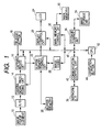
- Fig. 1 is a block diagram which schematically shows the structure of a digital camera in accordance with a first embodiment of the present invention.
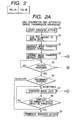
- Fig. 2 is comprised of Fig. 2A and Fig. 2B showing flowcharts which show the image transfer in accordance with the first embodiment of the present invention.
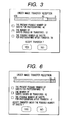
- Fig. 3 is a view which shows one example of the message appearing on the called side (incoming call) apparatus (an image reception apparatus).
- Fig. 4 is comprised of Fig. 4A and Fig. 4B showing flowcharts which show the image transfer in accordance with a second embodiment of the present invention.
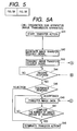
- Fig. 5 is comprised of Fig. 5A and Fig. 5B showing flowcharts which show the image transfer in accordance with a third embodiment of the present invention.
- Fig. 6 is a view which shows another example of the message appearing on the called side (incoming call) apparatus (the image reception apparatus).
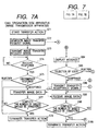
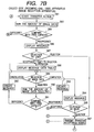
- Fig. 7 is comprised of Fig. 7A and Fig. 7B showing flowcharts which show the image transfer in accordance with a fourth embodiment of the present invention.
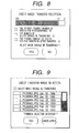
- Fig. 8 is a view which shows another example of the message appearing on the apparatus on the called (incoming call) side (the image reception apparatus).
- Fig. 9 is a view which shows still another example of the message appearing on the apparatus on the called (incoming call) side (the image reception apparatus).
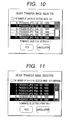
- Fig. 10 is a view which shows a further example of the message appearing on the apparatus on the called (incoming call) side (the image reception apparatus).
- Fig. 11 is a view which shows still a further example of the message appearing on the apparatus on the called (incoming call) side (the image reception apparatus).
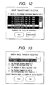
- Fig. 12 is a view which shows another example of the message appearing on the apparatus on the called (incoming call) side (the image reception apparatus).
- Fig. 13 is a view which shows still another example of the message appearing on the apparatus on the called (incoming call) side (the image reception apparatus).
- FIG. 1 is a block diagram which schematically shows a portable digital camera in accordance with a first embodiment of the present invention.
- a reference numeral 10 designates an image pickup element; 12, an A/D converter that converts the analogue image signals output from the image pickup element into the digital signals; 14, a camera signal processing circuit formed by a DSP (digital signal processor) that executes the camera signal process such as to make the y correction of the output data from the A/D converter, to adjust the color balance, among some others; 16, a capture resize circuit that fetches the output image data from the camera signal processing circuit 14 in accordance with the operation of the release button, and resizes the image data as required.
- DSP digital signal processor
- a reference numeral 20 designates a buffer memory that provisionally stores the photographed image data, and the reproduction image data as well; 22, a buffer memory control circuit that controls writing to and reading from the buffer memory 20; 24, a liquid crystal display (LCD) panel that serves as image display means; 26, a display control circuit that drives the liquid crystal display panel 24 and controls it; 28, an image CODEC (coder and decoder) that encodes (compresses) the image data and decodes (expands) the image data thus encoded.
- LCD liquid crystal display
- a reference numeral 30 designates a main memory formed by DRAM and others; 32, a main memory control circuits that controls writing to and reading from the main memory 30; 34, an image storage device which serves as the image storage medium, such as a non-volatile semiconductor memory, a magnetic disc, an optical disc, an opto-magnetic disc; 36, a storage control circuit that controls writing to and reading from the image storage device 34; 38, a network interface; 40, a communication control circuit; 42, a CPU that controls the entire system; 44, operation buttons through which various instructions are inputted to the CPU 42.
- an image storage device which serves as the image storage medium, such as a non-volatile semiconductor memory, a magnetic disc, an optical disc, an opto-magnetic disc
- 36 a storage control circuit that controls writing to and reading from the image storage device 34
- 38 a network interface
- 40 a communication control circuit
- 42 a CPU that controls the entire system
- 44 operation buttons through which various instructions are inputted to the CPU 42.
- the network interface 38 may be wired or arranged to be in a cordless mode.
- the CPU 42 is connected with each of the aforesaid circuits through the CPU bus 46. More specifically, the CPU is connected with the camera signal processing circuit 14, the capture resize circuit 16, the display control circuit 26, the image CODEC 28, the main memory control circuit 32, the storage control device 36, and the communication control circuit 40.
- the A/D converter 12 converts the analogue signals output form the image pickup element 10 into the digital signals.
- the camera signal processing circuit 14 executes the gain adjustment, the gamma correction, the white balance correction, the CCD filter-matrix correction and the color space converting operation, and some others for the data which have been output from the A/D converter 12, and generates the photographed image data which contain the synchronous information per unit of frame and line, respectively.
- the photographing parameters (the exposure time and the like) and each of the correction parameters are set for the camera signal processing circuit 14 by the CPU 42 through the CPU bus 46.
- the capture resize circuit 16 fetches in the image data output from the camera signal processing circuit 14, and converts the pixel density into the target space resolution (pixel numbers), and performs the filter process and others in order to compressively encode them by use of the image CODEC 28.
- the capture resize circuit 16 outputs to the buffer memory control circuit 22 the two kinds of photographed image data thus processed per frame unit for use of recording and thumb nail representation in accordance with the instruction signals of the image pickup timing provided by use of the release button 18.
- the buffer memory control circuit 22 provisionally stores the photographed image data from the capture resize circuit 16 on the buffer memory 20.
- the access request to the buffer memory 20 there are three kinds, that is, the write request of the photographed image data output from the capture resize circuit 16; the read request of the displayed image data from the display control circuit 26; and the read and write request of the photographed image data from the image CODEC 28.
- the buffer memory control circuit 22 performs the intervention and ordering controls with respect to these access requests.
- the display control circuit 26 drives the liquid crystal display panel 24 to display images in accordance with the display image data read out from the buffer memory 20 through the buffer memory control circuit 22.
- the buffer memory control circuit 22 complies with the periodical read-out request of the display image data from the display control circuit 26, and supplies the photographed image data for use of recording, which have been stored in a specific region of the buffer memory 20, to the display control circuit 26.
- the image CODEC 28 reads in from the buffer memory 20 the two kinds of the photographed image data for use of recording and thumb nail representation, and encodes them compressively and respectively.
- the two kinds of encoded image data thus compressively encoded by the image CODEC 28 are provisionally stored on specific region of the main memory 30 through the CPU bus 46.
- the operation of the image CODEC 28 of the compression encoding is initiated immediately the moment the photographed image data begin to be stored on the buffer memory 20 or the storage to the buffer memory 20 is completed.
- the main memory control circuit 32 controls the access of writing to and reading from the main memory 30.
- the main memory control circuit 32 performs the intervention and ordering controls of these access orders.
- the CPU 42 transfers sequentially to the image storage device 34 the two kinds of encoded image data for use of recording and thumb nail representation which have been provisionally stored on the main memory 30.
- the storage control circuit 36 controls the writing and reading accesses for the image storage device 34. For the access requests to the image storage device 34, there are the reading and writing accesses of various data including the encoded image data provided by the CPU 42.
- the CPU 42 deletes the encoded image data obtained from the main memory 30, and then, returns to the next photographing operation.
- the description will be made of the reproducing operation of the image data stored on the image storage device 34.
- the user designates the image that should be reproduced by use of the operation button 44.
- the CPU 42 instructs the storage control circuit 36 to read from the image storage device 34 the encoded image data of the designated image, and store them on a specific region of the main memory 30.
- the image CODEC 28 reads out the encoded image data for use of recording, which have been read out from the image storage device 34 and stored on the specific region of the main memory 30, and supplies them to the buffer memory control circuit 22 after the execution of the expansion decoding process.
- the buffer memory control circuit 22 stores the reproducing image data from the image CODEC 28 on a specific region of the buffer memory 20.
- the display control circuit 26 reads out the reproducing image data on the buffer memory 20 periodically as in the case of the photographed image data, and drives the liquid crystal display panel 24 in accordance with the image data, and displays images on the liquid crystal display panel 24.
- FIGs. 2A and 2B are flowcharts which show the operation thereof. It is assumed that the image data is usually transferred under the compressed condition.
- each of the steps shown in Figs. 2A and 2B is executed by the program that operates on the CPU 42.
- Both the apparatuses on the call originating side and called side are structured as shown in Fig. 1.
- the apparatus on the call originating side serves as the image transmission apparatus, and the apparatus on the called side serves as the image reception apparatus.
- a reference mark 'S' is added to each constituent of the apparatus on the call originating side, and a reference mark 'R' is added to that of the apparatus on the called side.
- the CPU 42S When the user operates a specific image transmission on the apparatus on the call originating side (image transmission apparatus), the CPU 42S begins a series of the operational sequence of the image transfer.
- one or more image data (image files), which are designated by the user for transmission by use of the operation button 44S, are read out from the image storage device 34S and stored on the specific region of the main memory 30S (S1).
- the amount of data (the file capacity) of one or more image data thus designated for transmission are all added or the sheet number of images is added in order to calculate the sum thereof (S2).
- the image transfer request signal is generated on the main memory, containing the sum of the image data or the sheet number of images calculated in the step S2 (S3).
- the apparatus on the call originating side actuates the communication control circuit 40S to call the apparatus on the called side by use of the network interface 38S.
- the image transfer request signal is transmitted to the apparatus on the called side (S4).
- the apparatus on the call originating side waits for the response from the apparatus on the called side (S5) after having transmitted the image transfer request signal.
- the apparatus on the called side apparatus detects the call from the apparatus on the call originating side, and receives the image transfer request signal after the link has been established (S11). Then, it begins a series of the operational sequence of the transfer on S12 and on. In other words, the apparatus on the called side calculates the free (unused) storage capacity of the image storage device 34R (or reads out the data on the sheet number of photographs that can be taken, which is controlled and managed separately), and reads out the sum of the target image data to be transferred on the basis of the image transfer request signal which has been received previously or the information of the sheet number of images, hence comparing them with each other (S12).
- the CPU 42R displays the message and graph shown in Fig. 3 on the liquid crystal panel 24R (S13).
- the message "the sheet number of photographs that can be taken at present” is the value of the data on the sheet number of photographs that can be taken and stored on the image storage device 34R
- the message “the sheet number of the images to be transferred” is the sheet number of images that should be transferred from the apparatus on the call originating side.
- the message "the sheet number of photographs that can be taken after transfer” is the sheet number of photographs that can be still taken subsequent to having stored all the transferred images on the image storage device 34R.
- the CPU waits for the operation of the user (S14) after having displayed the messages and flags.
- the user of the apparatus on the called side can select whether he accepts or he should refuse the transfer operation in accordance with the messages appearing on the screen shown in Fig. 3. He depresses the "YES” or "NO” instruction button, which corresponds to the desired operation accordingly (S14). The result of this operation is provided for the CPU 42R.
- the apparatus on the called side transmits the transfer acceptance signal to the apparatus on the call originating side (S16), thus receiving the image data actually (S17 and S18).
- the "NO" button is depressed (S14)
- the transfer refusal (rejection) signal is transmitted to the apparatus on the call originating side (S15).
- the discrimination is made to determine whether the response is an acceptance or a refusal (S6).
- the signal of transfer refusal is received, the message to the effect that the transfer request has been refused by the apparatus on the called side is displayed on the liquid crystal panel 24S, although not shown in Figs. 2A and 2B in particular, hence terminating a series of the operational sequence of the transfer (S9).
- the transfer acceptance signal is received (S6), the image data having the sheet number which has been initially designated is transmitted actually (S7, and S8). After that, the transfer operation terminates. Then, if necessary, the link with the apparatus on the called side is cut off (S9).
- the apparatus on the called side receives the image data until it has reached the initially designated sheet number after transmitting the transfer acceptance signal to the apparatus on the call originating side (S17 and S18).
- the transfer operation terminates, and the link with the apparatus on the call originating side is cut off (S19).
- the apparatus on the called side (image reception apparatus) transmits the transfer refusal signal to the apparatus on the call originating side (S15) if the free storage capacity of the image storage device 34R is insufficient (S12). Then, the apparatus on the called side terminates the transfer operation after having transmitted the transfer refusal signal, and cuts off the link with the apparatus on the call originating side (S19).
- Figs. 4A and 4B are flowcharts which show another example of image transfer.
- the CPU 42S begins a series of the operational sequence of the image transfer.
- one or more image data which are designated by the user for transmission by use of the operation button 44S, are read out from the image storage device 34S and stored on the specific region of the main memory 30S (S21).
- the image transfer request signal is generated (S22), which contains the information of each identification name (file name) and each file capacity of the target image data to be transmitted (S22).
- the apparatus on the call originating side actuates the communication control circuit 40S to call the apparatus on the called side by use of the network interface 38S.
- the image transfer request signal is transmitted to the apparatus on the called side (S23).
- the apparatus on the call originating side waits for the response from the apparatus on the called side (S24) after having transmitted the image transfer request signal.
- the apparatus on the called side detects the call from the apparatus on the call originating side, and receives the image transfer request signal after the link has been established (S31). Then, it begins a series of the operational sequence of the transfer on S32 and on. In other words, the apparatus on the called side calculates the total sheet number (or the total data amount) in accordance with the each identification name (file name) of the image data contained in the image transfer request signal which has been received (S32). Then, it calculates the recordable number of sheets by the image storage device 34R (or free storage capacity thereof), hence comparing the results thereof with the total sheet number (or the total data amount) of the target image data of the image transfer request (S33).
- the CPU 42R displays the messages and graphs shown in Fig. 3 on the liquid crystal panel 24R (S34). Then, the CPU waits for the operation of the user (S35) after having displayed the messages and flags.
- the user of the apparatus on the called side can select whether he accepts or he should refuse the transfer operation in accordance with the messages appearing on the screen shown in Fig. 3. He depresses the "YES” or "NO” instruction button, which corresponds to the desired operation accordingly (S34). The result of this operation is provided for the CPU 42R.
- the apparatus on the called side transmits the transfer acceptance signal to the apparatus on the call originating side (S37), thus receiving the image data actually (S38 and S39).
- the "NO" button is depressed (S35)
- the transfer refusal signal is transmitted to the apparatus on the call originating side (S36).
- the discrimination is made to determine whether the response is an acceptance or a refusal (S25).
- the signal of transfer refusal is received, the message to the effect that the transfer request has been refused by the apparatus on the called side is displayed on the liquid crystal panel 24S, although not shown in Figs. 2A and 2B in particular, hence terminating a series of the operational sequence of the transfer (S28).
- the transfer acceptance signal is received (S25)
- the image data having the sheet number which has been initially designated is transmitted actually (S26, and S27). After that, the transfer operation terminates. Then, if necessary, the link with the apparatus on the called side is cut off (S28).
- the apparatus on the called side receives the image data until it has reached the initially designated sheet number after transmitting the transfer acceptance signal to the apparatus on the call originating side (S38 and S39).
- the transfer operation terminates, and the link with the apparatus on the call originating side is cut off (S40).
- the apparatus on the called side transmits the transfer refusal signal to the apparatus on the call originating side (S36) if the free storage capacity of the image storage device 34R is insufficient (S33).
- the apparatus on the called side transmits the transfer refusal signal to the apparatus on the call originating side (S35). Then, it cuts off the link with the apparatus on the call originating side (S40).
- Figs. 5A and 5B are flowcharts which show the example of transfer process in accordance with a third embodiment of the present invention.
- Fig. 6 exemplifies the display screen of the image reception apparatus.
- the operation of the apparatus on the call originating side (S41 to S48) is the same as the one described in conjunction with Figs. 4A and 4B.
- the operation of the apparatus on the called side is partly different from the one described in conjunction with Figs. 4A and 4B. Therefore, the description will be made mainly of the operation of the apparatus on the called side.
- the apparatus on the called side detects the call from the apparatus on the call originating side, and receives the image transfer request signal after the link has been established (S51). Then, it begins a series of the operational sequence of the transfer on S52 and on. In other words, the apparatus on the called side calculates the total sheet number (or the total data amount) in accordance with the each identification name (file name) of the image data contained in the image transfer request signal which has been received (S52). Then, it calculates the recordable number of sheets by the image storage device 34R (or free storage capacity thereof), hence comparing the results thereof with the total sheet number (or the total data amount) of the target image data of the image transfer request (S53).
- the CPU 42R When the free storage capacity of the image storage device 34R is sufficient (S53), the CPU 42R generates the image transfer acceptance signal which contains the information indicating that all the image data of the target transfer are receivable, and displays the messages and graphs shown in Fig. 3 on the liquid crystal panel 24R (S54). On the other hand, if the free storage capacity of the image storage device 34R is insufficient (S53), the CPU 42R generates the image transfer acceptance signal which contains the information that specifies the image data of the maximum sheet number receivable within the range of the free storage capacity, and displays the messages and flags shown in Fig. 6 on the screen of the liquid crystal display panel 24R (S55).
- the image transfer acceptance signal is generated in accordance with the image transfer request signal transmitted from the apparatus on the call originating side, and this signal contains each identification name (file name) of each image data.
- the apparatus on the called side transmits the transfer refusal signal to the apparatus on the call originating side (S35). Then, it cuts off the link with the apparatus on the call originating side (S40).
- the message "the sheet number of photographs that can be taken at present” is the value of the data on the sheet number of photographs that can be taken and stored on the image storage device 34R, and the message “the sheet number of the images to be transferred” is the sheet number of images that should be transferred from the apparatus on the call originating side.
- the message "the sheet number of photographs that can be taken after transfer” is the sheet number of photographs that can be still taken subsequent to having stored all the transferred images on the image storage device 34R. Here, it is impossible to receive all the images, the message " the sheet number of photographs that can be taken after transfer” indicates a negative value.
- the CPU waits for the operation of the user (S54 and S55).
- the user of the apparatus on the called side can select whether he accepts or he should refuse the transfer operation in accordance with the messages appearing on the screen shown in Fig. 3 or Fig. 6. He depresses the "YES” or "NO” instruction button, which corresponds to the desired operation accordingly (S56). This operation is provided for the CPU 42R.
- the apparatus on the called side transmits the transfer acceptance signal to the apparatus on the call originating side (S58), thus receiving the image data actually (S59 and S60).
- the transfer refusal signal is transmitted to the apparatus on the call originating side (S57).
- the discrimination is made to determine whether the response is an acceptance or a refusal (S45).
- the signal of transfer refusal is received, the message to the effect that the transfer request has been refused by the apparatus on the called side is displayed on the liquid crystal panel 24S, although not shown in Figs. 5A and 5B in particular, hence terminating a series of the operational sequence of the transfer (S48). If the transfer acceptance signal is received (S45), the message to the effect that the transfer of all the image data is accepted totally as request or the transfer is made partly on the screen of the liquid crystal display panel 24S.
- the image data whose transfer has been accepted is transmitted sequentially and actually (S46 and S47).
- the apparatus on the called side receives the image data until it has reached the initially designated sheet number after transmitting the transfer acceptance signal to the apparatus on the call originating side (S59 and S60).
- the apparatus on the called side transmits the transfer refusal signal to the apparatus on the call originating side Then, it cuts off the link with the apparatus on the call originating side (S61).
- the CPU 42R For the transfer process in accordance with the third embodiment described above, the CPU 42R generates the image transfer acceptance signal which contains the information that specifies the maximum sheet number of the image data within the range of the free storage capacity if the free storage capacity of the image storage device 34R is insufficient (S53).
- the resultant sheet number of the photographs that can be still taken on the apparatus on the called side becomes "0" inevitably when the transfer operation is completed.
- another embodiment of transfer process may be easily conceivable wherein a step is added immediately after the step S55 to enable the user of the apparatus on the called side to designate the sheet number of the target image data for the transfer operation so that the sheet number of photographs that can be still taken after the competition of the transfer operation may become "1" or more.
- Figs. 7A and 7B are flowcharts which show the example of transfer process in accordance with a fourth embodiment of the present invention.
- Fig. 8 to Fig. 13 are views which illustrate the examples of the display screen of the image reception apparatus.
- the operation of the apparatus on the call originating side (S71 to S78) is the same as the one described in conjunction with Figs. 4A and 4B.
- the operation of the apparatus on the called side is partly different from the one described also in conjunction with Figs. 4A and 4B. Therefore, the description will be made mainly of the operation of the apparatus on the called side.
- the apparatus on the called side detects the call from the apparatus on the call originating side, and receives the image transfer request signal after the link has been established (S81). Then, it begins a series of the operational sequence of the transfer on S82 and on. In other words, the apparatus on the called side calculates, at first, the total sheet number (or the total data amount) in accordance with the each identification name (file name) of the image data contained in the image transfer request signal which has been received (S82). Then, it calculates the recordable number of sheets by the image storage device 34R (or free storage capacity thereof), hence comparing the results thereof with the total sheet number (or the total data amount) of the target image data of the image transfer request (S83).
- the CPU 42R When the free storage capacity of the image storage device 34R is sufficient (S83), the CPU 42R generates the image transfer acceptance signal which contains the information indicating that all the image data of the target transfer are receivable, and displays the messages and graphs shown in Fig. 3 on the liquid crystal panel 24R (S84).
- the CPU waits for the operation of the user (S84).
- the user of the apparatus on the called side can select whether he accepts or he should refuse the transfer operation in accordance with the messages appearing on the screen shown in Fig. 3. He depresses the "YES” or "NO” instruction button, which corresponds to the desired operation accordingly (S85). This operation is provided for the CPU 42R.
- the apparatus on the called side transmits the transfer acceptance signal to the apparatus on the call originating side (S96), thus receiving the image data actually (S98 and S99).
- the "NO" button is depressed (S85)
- the transfer refusal signal is transmitted to the apparatus on the call originating side (S97).
- the CPU 42R displays the messages and flags shown in Fig. 8 on the screen of the liquid crystal panel 24R in order to prompt whether the selection is made for each individual image data to be received within the range of the free storage capacity or the selection is made for the refusal of the receiving operation as a whole (S86).
- the message “the sheet number of photographs that can be taken at present” is the value of the data on the sheet number of photographs that can be taken and stored on the image storage device 34R
- the message “the sheet number of the images to be transferred” is the sheet number of images that should be transferred from the apparatus on the call originating side.
- the message “the sheet number of photographs that can be taken after transfer” is the sheet number of photographs that can be still taken subsequent to having stored all the transferred images on the image storage device 34R.
- the message “the sheet number of photographs that can be taken after transfer” indicates a negative value.
- the CPU waits for the operation of the user (S86). Since the user of the apparatus on the called side can select whether he proceeds to the operation to select the target image data for the transfer operation or he refuses the transfer operation as a whole in accordance with the messages appearing on the screen shown in Fig. 8, he may depress the "YES” or "NO” instruction button, which corresponds to the desired operation accordingly (S86). This operation is provided for the CPU 42R.
- the apparatus on the called side When the "YES" button is depressed (S87), the apparatus on the called side prompts the user to make the selection of the target image data for the transfer operation, and at the same time, displays on the screen of the liquid crystal panel 24R the list of the image data requested by the apparatus on the call originating side as the target for the transfer operation as shown in Fig. 9 (S88).
- the transfer refusal signal is transmitted to the apparatus on the call originating side (S97).
- the list of the image data requested by the apparatus on the call originating side as the target of the transfer operation, which is shown on the screen of the liquid crystal display panel 24R, is formed in accordance with each identification name (file name) of the image data contained in the image transfer request signal received in the S81.
- the so-called scrolling display method is adopted, because the number of sheets (12) of the transmitting images thus requested is larger than the sheet number of image data (six) that can be displayed at a time within the arrangement limit of the display layout.
- one sheet of image data is selected, and at each time such selection is made (S89), the total sheet number (or the total data amount) is calculated for the image data selected by the user up to the present in accordance with the file capacity of the selected image data (S90). Then, the number Of recordable sheet of the image storage apparatus 34R (or the free storage capacity thereof) is calculated, then comparing it with the total sheet number or the total data amount) of the image data selected by the aforesaid user (S91).
- the CPU 42R updates the list of the transfer image data shown on the screen of the liquid crystal display panel 24R in order to indicate that the image data selected by the user in the step S89 has been accepted as the target of the transfer operation (S92).
- Fig. 10 shows the example of the list of the transfer image data which is thus updated. As shown in Fig. 10, the image data that have been selected as the target of the transfer operation are represented each in the reversed black and white indication.
- the CPU 42R indicates that the image data selected by the user in the step S89 is accepted as the target of the transfer operation, and updates the list of the transfer image data shown on the screen of the liquid crystal display panel 24R in order to show the total sheet number of the image data which have been selected up to the present arrives at the maximum value (S92).
- Fig. 11 shows the example of the list of the transfer image data thus updated. As shown in Fig.
- the CPU 42R indicates that the image data selected by the user in the step S89 has been accepted as the target of the transfer operation, and updates the list of the transfer image data shown on the screen of the liquid crystal display panel 24R in order to show the total sheet number of the image data which have been selected up to the present arrives at the maximum value (S92).
- Fig. 12 shows the example of the list of the transfer image data thus updated.
- the maximum transferable number of sheets it is indicated that the transfer sheet number of images already selected has arrived at the maximum value as shown in Fig. 12.
- the apparatus on the called side When a series of operation to select the transfer image data by the user on the apparatus on the called side are completed with the depression of the "YES" instruction button of the operation buttons 44R as shown in Fig. 10 to Fig. 12 (S89), the apparatus on the called side generates the image transfer acceptance signal which contains the information indicating that only the image data selected by the user is acceptable for reception, and displays the messages and graphs shown in Fig. 13 on the liquid crystal panel 24R (S95).
- the phrase “the sheet number of selected transfer images” is the sheet number of the images selected by the user on the apparatus on the called side as the target of the transfer operation in a series of the aforesaid operation of selections
- the phrase “the sheet number of photographs that can be still taken after transfer” is the sheet number of photographs that can be still taken after having stored all the transferred images on the image storage device 34R.
- the CPU waits for the operation of the user (S95).
- the user of the apparatus on the called side can select whether he accepts or he should refuse the transfer operation in accordance with the messages appearing on the screen shown in Fig. 13. He depresses the "YES” or "NO” instruction button of the operation buttons 44R, which corresponds to the desired operation accordingly (S95). This operation is provided for the CPU 42R.
- the apparatus on the called side transmits the transfer acceptance signal to the apparatus on the call originating side (S96), thus receiving the image data actually (S98 and S99).
- the "NO" button is depressed (S95)
- the transfer refusal signal is transmitted to the apparatus on the call originating side (S97).
- the apparatus on the called side does not display the list of the image data shown in Fig. 9 on the screen of the liquid crystal display panel 24R (S88). The process returns to the initial status of the series of the operation of the user to select the image data (S89).
- the discrimination is made to determine whether the response is an acceptance or a refusal (S75).
- the signal of transfer refusal is received, the message to the effect that the transfer request has been refused by the apparatus on the called side is displayed on the liquid crystal panel 24S, although not shown in Figs. 7A and 7B in particular, hence terminating a series of the operational sequence of the transfer (S78). If the transfer acceptance signal is received (S75), the message to the effect that the transfer of all the image data is accepted totally as request or the transfer is made partly on the screen of the liquid crystal display panel 24S.
- the image data whose transfer has been accepted is transmitted sequentially and actually (S76 and S77).
- the apparatus on the called side receives the image data until it has reached the initially designated sheet number after transmitting the transfer acceptance signal to the apparatus on the call originating side (S98 and S99).
- the transfer operation terminates, and the link with the apparatus on the call originating side is cut off (S100).
- the apparatus on the called side transmits the transfer refusal signal to the apparatus on the call originating side Then, it cuts off the link with the apparatus on the call originating side (S100).
- the process, in which the apparatus on the call originating side adds to the image transfer request signal the information of thumb nail images of each image together with the identification name (file name) thereof, is not necessarily limited to the transfer process in accordance with the fourth embodiment.
- This additional process of thumb nail image information is applicable to all the transfer processes in accordance with the first to third embodiments.
- the thumb nail image information of each image data requested for transfer still remains on the apparatus on the called side even when the like is cut off by the user of the apparatus on the called side due to his refusal of the transfer operation process as a whole. Therefore, this process to provide such additional information is still effective at least for the maintenance of a better communication between the users on the call originating side and called side.
- the sheet number of the image data is selected by the user of the apparatus on the called side as the target of the transfer operation within the range of the maximum sheet number in the receivable range of the free storage capacity of the apparatus on the called side if the free storage capacity of the image storage device 34R is insufficient (S53), and also, in accordance with the transfer process of the fourth embodiment, the image data is selected by the user of the apparatus on the called side as the target of the transfer operation within the range of the maximum sheet number in the receivable range of the free storage capacity of the apparatus on the called side if the free storage capacity of the image storage device 34R is insufficient (S83).
- connection type linkage also, the description has been made of the examples of the connection type linkage. However, this invention is obviously applicable to the connectionless type linkage with the exception of the connection probability and the cut off process thereof.
- the file name shown in Fig. 9 may be manually inputted by the user of the apparatus on the call originating side through the operation button 44S of the apparatus on that side.
- the GPS global positioning system
- the information of the position photographed by a digital camera on the apparatus on the call originating side is referenced to the map information held separately by the apparatus on the call originating side on the main memory 30, and the locational information on the map, which has been obtained as a result of such reference, may be added to the file name.
- the structure so that the information of priority order is added to the image (file) selected by the operator of the apparatus on the call originating side when the image (file) is selected for transmission.
- the structure may be arranged to display the priority order information on the display unit of the apparatus on the called side, while linking with the file name information as shown in Fig. 9. Then, it is made possible for the operator on the apparatus on the called side to select the file (image) with attention given to the intention of the operator of the apparatus on the call originating side in this respect.
- the apparatus on the called side may reproduce the comment (audio memorandum) concerning the file by use of an audio device with the provision of the audio input, reproduction, and audio output functions (not shown) both for the apparatuses on the call originating and called sides, while making it possible to designate the file name on the display unit shown in Fig. 9.
- the operator of the apparatus on the call originating side which is designated in advance by use of the audio input function on the apparatus on the call originating side, adds the comment (audio memorandum) to each of the files as the image transfer signal, thus making it possible to select the file while referencing such comment on each file when the selection is made as shown in Fig. 9.
- the structure is arranged to enable the operator of the digital camera to photograph in a specific number of sheets by use of the main memory 30 even in the midst of the transmission of the image (file) to the apparatus on the called side or in the midst of the reception from the apparatus on the call originating side.
- the operator intends to photograph to the extent that the capacity of the main memory 30 becomes insufficient on the apparatus on the call originating side or on the apparatus on the called side, it may be possible to give a warning sound accordingly by use of the audio output function (not shown) of the digital camera so as to notify the operator that he is unable to take photographs any more.
- Such notification means is not necessarily limited to the audio device. In other words, it may be possible to implement such notification means without causing any trouble to the users other than the operator of the digital camera by supporting such function on the liquid crystal display panel 24 or in the finder (not shown) of the digital camera as to indicate the information regarding the memory capacity of the main memory 30 or display the warning message when the memory capacity becomes insufficient.
- the current photographing may be suspended or it may be desired to continue photographing as a matter of course even though the current communication should be suspended.
- an operation button is installed on the digital camera of the embodiments described above to suspend communication compulsorily.
- the structure should be arranged so as to display the instruction for the replacement of the detachable memory depending on the results of the free storage capacity comparison on the apparatus on the called side to decide on whether or not the capacity of the image storage device 34R is insufficient.
- this structure makes it possible for the operator of the apparatus on the called side to receive the images which are transmitted from the apparatus on the call originating side if only he has more image storage devices 34 in hand preparatorily.
- it is arranged to register on the apparatus on the called side in advance the address information of some other apparatus (a computer or a portable terminal) which is made available to the operator of the apparatus on the called side, and then, the arrangement is made so that when the response is transmitted to the apparatus on the call originating side as to the information that indicates the selected image (file), the aforesaid address information is also transmitted to the apparatus on the call originating side in order to allow the images (files) which are not selected to be transmitted from the apparatus on the call originating side to the above-described some other apparatus as required.
- some other apparatus a computer or a portable terminal
- the apparatus on the call originating side transmits the selected image (file) to the apparatus on the called side, while transmitting each of the images (files) which is not selected to the aforesaid apparatus using the address information thus provided.
- a program is stored on a storage medium to enable each of the structures thereof to operate, and then, such stored program is read out as codes to execute processes as in the embodiments by means of a client computer and a server computer. It is then construed that such method is within the scope of the above-described embodiments, and that the storage medium having the aforesaid program stored thereon is also within the scope of the above-described embodiments.
- a floppy disc As such storage medium, it is possible to use a floppy disc, a hard disc, an optical disc, an opto-magnetic disc, a CD-ROM, a magnetic tape, a non-volatile memory card, and a ROM, for example.
- the apparatus on the image reception side is arranged for the apparatus on the image reception side to indicate the free storage capacity in advance when images are received. This indication is significantly useful at determining the acceptance or the refusal of the image transfer.
Landscapes
- Engineering & Computer Science (AREA)
- Multimedia (AREA)
- Signal Processing (AREA)
- Computer Networks & Wireless Communication (AREA)
- General Engineering & Computer Science (AREA)
- Telephonic Communication Services (AREA)
- Facsimiles In General (AREA)
- Storing Facsimile Image Data (AREA)
- Facsimile Transmission Control (AREA)
- Information Transfer Between Computers (AREA)
- Television Signal Processing For Recording (AREA)
Applications Claiming Priority (4)
| Application Number | Priority Date | Filing Date | Title |
|---|---|---|---|
| JP7195298 | 1998-03-20 | ||
| JP07195298 | 1998-03-20 | ||
| JP06587499 | 1999-03-12 | ||
| JP06587499A JP4298042B2 (ja) | 1998-03-20 | 1999-03-12 | ディジタルカメラ及びその制御方法 |
Publications (3)
| Publication Number | Publication Date |
|---|---|
| EP0944240A2 true EP0944240A2 (fr) | 1999-09-22 |
| EP0944240A3 EP0944240A3 (fr) | 2000-08-23 |
| EP0944240B1 EP0944240B1 (fr) | 2009-01-14 |
Family
ID=26407036
Family Applications (1)
| Application Number | Title | Priority Date | Filing Date |
|---|---|---|---|
| EP99302128A Expired - Lifetime EP0944240B1 (fr) | 1998-03-20 | 1999-03-18 | Transmission d'images |
Country Status (5)
| Country | Link |
|---|---|
| US (2) | US7148915B1 (fr) |
| EP (1) | EP0944240B1 (fr) |
| JP (1) | JP4298042B2 (fr) |
| CN (1) | CN1187954C (fr) |
| DE (1) | DE69940285D1 (fr) |
Cited By (6)
| Publication number | Priority date | Publication date | Assignee | Title |
|---|---|---|---|---|
| EP1294173A3 (fr) * | 2001-09-12 | 2004-01-21 | Brother Kogyo Kabushiki Kaisha | Système de transmission/réception de données informant un utilisateur de la transmission de données d'image |
| EP1298914A3 (fr) * | 2001-09-27 | 2005-04-20 | Fuji Photo Film Co., Ltd. | Mèthode de transmission d'image, caméra numérique, mèthode et dispositif de stockage d'image et logiciel à cette fin |
| EP1637988A3 (fr) * | 2004-06-30 | 2007-05-02 | Samsung Electronics Co., Ltd. | Transmission de données entre un appareil principal et un appareil secondaire |
| EP1237074A3 (fr) * | 2000-12-27 | 2009-04-29 | Kabushiki Kaisha Toshiba | Procédé et dispositif pour la distribution des données numérique |
| US7551210B2 (en) * | 2001-09-26 | 2009-06-23 | Fujifilm Corporation | Image data transfer method, digital camera, and program |
| EP2158947A3 (fr) * | 2008-07-11 | 2014-11-26 | Nintendo Co., Ltd. | Système de communication d'images, appareil de communication d'images, et support de stockage disposant du programme de communication d'images stocké sur celui-ci |
Families Citing this family (15)
| Publication number | Priority date | Publication date | Assignee | Title |
|---|---|---|---|---|
| JP2002352218A (ja) * | 2001-05-24 | 2002-12-06 | Olympus Optical Co Ltd | ファイル名設定システム、電子カメラ、及び情報処理装置 |
| GB0129614D0 (en) * | 2001-12-11 | 2002-01-30 | Nokia Corp | Asynchronous serial data interface |
| JP4219196B2 (ja) * | 2003-03-19 | 2009-02-04 | シャープ株式会社 | 画像送信装置 |
| JP2005020452A (ja) * | 2003-06-26 | 2005-01-20 | Ricoh Co Ltd | 撮像装置 |
| US20060149747A1 (en) * | 2005-01-05 | 2006-07-06 | Bair Jason D | System for establishing priorities in distributed capture operations |
| US7940908B2 (en) * | 2006-02-23 | 2011-05-10 | Qualcomm Incorporated | Sharing profile data between telecommunication devices |
| US7822891B2 (en) * | 2006-06-13 | 2010-10-26 | Broadcom Corporation | System and method for transferring a multidimensional array of data to a non-contiguous buffer |
| EP1936946B1 (fr) * | 2006-12-22 | 2019-06-19 | Brother Kogyo Kabushiki Kaisha | Processeur de données |
| JP4934708B2 (ja) * | 2009-09-09 | 2012-05-16 | 株式会社 沖情報システムズ | 画像処理システム |
| CN110798586A (zh) * | 2010-02-19 | 2020-02-14 | 株式会社尼康 | 电子设备 |
| JP5620851B2 (ja) * | 2010-08-17 | 2014-11-05 | パナソニック株式会社 | 電子機器、電子機器システム及び画像処理方法 |
| CN103970781A (zh) * | 2013-01-30 | 2014-08-06 | 深圳市同洲电子股份有限公司 | 嵌入式浏览器图片解码装置及方法 |
| CN108462817B (zh) * | 2017-02-22 | 2021-01-05 | 佳能株式会社 | 通信装置及其控制方法和存储介质 |
| JP6977010B2 (ja) * | 2018-09-14 | 2021-12-08 | キヤノン株式会社 | 画像処理装置、画像処理装置の制御方法、及びプログラム |
| CN118870096A (zh) * | 2024-06-28 | 2024-10-29 | 海信视像科技股份有限公司 | 一种显示设备及导入照片的方法 |
Family Cites Families (22)
| Publication number | Priority date | Publication date | Assignee | Title |
|---|---|---|---|---|
| US4672460A (en) | 1983-03-30 | 1987-06-09 | Canon Kabushiki Kaisha | Facsimile apparatus |
| US5220439A (en) | 1988-05-17 | 1993-06-15 | Canon Kabushiki Kaisha | Facsimile apparatus having improved memory control for error-correcting and non-error-correcting modes |
| JP2999490B2 (ja) | 1989-10-30 | 2000-01-17 | 株式会社東芝 | 電子カメラおよび画像記録方法 |
| JP3103151B2 (ja) | 1990-09-03 | 2000-10-23 | 富士写真フイルム株式会社 | 電子スチル・カメラおよびその動作制御方法 |
| JPH0541764A (ja) | 1991-08-06 | 1993-02-19 | Hitachi Ltd | 電子フアイル装置によるデータ転送方法 |
| US5717496A (en) * | 1992-11-19 | 1998-02-10 | Olympus Optical Co., Ltd. | Electronic imaging apparatus |
| JPH0646221A (ja) | 1992-07-24 | 1994-02-18 | Hitachi Ltd | 画像処理装置および方法 |
| US5432871A (en) * | 1993-08-04 | 1995-07-11 | Universal Systems & Technology, Inc. | Systems and methods for interactive image data acquisition and compression |
| US5805215A (en) * | 1994-04-21 | 1998-09-08 | Canon Kabushiki Kaisha | Information processing method and apparatus for storing additional data about an image |
| JP3552748B2 (ja) | 1994-05-16 | 2004-08-11 | オリンパス株式会社 | 電子画像取扱装置及び電子画像取扱システム |
| JP3504738B2 (ja) * | 1994-09-09 | 2004-03-08 | オリンパス株式会社 | 電子的撮像装置及び電子的撮像システム |
| JP3893480B2 (ja) * | 1994-09-28 | 2007-03-14 | 株式会社リコー | デジタル電子カメラ |
| US5648816A (en) * | 1995-01-31 | 1997-07-15 | Asahi Kogaku Kogyo Kabushiki Kaisha | Still video camera including detachably attachable external memory |
| JP3863202B2 (ja) | 1995-02-24 | 2006-12-27 | 富士フイルムホールディングス株式会社 | 画像データ伝送システムおよび画像データ伝送方法 |
| JP4031841B2 (ja) * | 1995-09-05 | 2008-01-09 | 株式会社コダックデジタルプロダクトセンター | デジタルカメラ |
| US6282362B1 (en) * | 1995-11-07 | 2001-08-28 | Trimble Navigation Limited | Geographical position/image digital recording and display system |
| US6188431B1 (en) * | 1996-02-17 | 2001-02-13 | Casio Computers Co., Ltd. | Electronic still camera and method for communication between electronic still cameras |
| JPH1056609A (ja) * | 1996-04-15 | 1998-02-24 | Canon Inc | 画像記録方法、通信方法、画像記録装置、通信装置及び媒体 |
| JPH10200842A (ja) * | 1997-01-07 | 1998-07-31 | Minolta Co Ltd | デジタルカメラ |
| US20040051785A1 (en) * | 1997-06-06 | 2004-03-18 | Nikon Corporation | Electronic camera having a communication function |
| US6522354B1 (en) * | 1997-06-09 | 2003-02-18 | Nikon Corporation | Electronic camera and method of operating an electronic camera |
| US6535243B1 (en) * | 1998-01-06 | 2003-03-18 | Hewlett- Packard Company | Wireless hand-held digital camera |
-
1999
- 1999-03-12 JP JP06587499A patent/JP4298042B2/ja not_active Expired - Fee Related
- 1999-03-17 US US09/271,247 patent/US7148915B1/en not_active Expired - Fee Related
- 1999-03-18 DE DE69940285T patent/DE69940285D1/de not_active Expired - Lifetime
- 1999-03-18 EP EP99302128A patent/EP0944240B1/fr not_active Expired - Lifetime
- 1999-03-19 CN CNB991062868A patent/CN1187954C/zh not_active Expired - Fee Related
-
2006
- 2006-10-31 US US11/555,057 patent/US7671906B2/en not_active Expired - Fee Related
Cited By (7)
| Publication number | Priority date | Publication date | Assignee | Title |
|---|---|---|---|---|
| EP1237074A3 (fr) * | 2000-12-27 | 2009-04-29 | Kabushiki Kaisha Toshiba | Procédé et dispositif pour la distribution des données numérique |
| EP1294173A3 (fr) * | 2001-09-12 | 2004-01-21 | Brother Kogyo Kabushiki Kaisha | Système de transmission/réception de données informant un utilisateur de la transmission de données d'image |
| US7742184B2 (en) | 2001-09-12 | 2010-06-22 | Brother Kogyo Kabushiki Kaisha | Data transmission/reception system that informs a user that image data has been transmitted |
| US7551210B2 (en) * | 2001-09-26 | 2009-06-23 | Fujifilm Corporation | Image data transfer method, digital camera, and program |
| EP1298914A3 (fr) * | 2001-09-27 | 2005-04-20 | Fuji Photo Film Co., Ltd. | Mèthode de transmission d'image, caméra numérique, mèthode et dispositif de stockage d'image et logiciel à cette fin |
| EP1637988A3 (fr) * | 2004-06-30 | 2007-05-02 | Samsung Electronics Co., Ltd. | Transmission de données entre un appareil principal et un appareil secondaire |
| EP2158947A3 (fr) * | 2008-07-11 | 2014-11-26 | Nintendo Co., Ltd. | Système de communication d'images, appareil de communication d'images, et support de stockage disposant du programme de communication d'images stocké sur celui-ci |
Also Published As
| Publication number | Publication date |
|---|---|
| US7671906B2 (en) | 2010-03-02 |
| EP0944240A3 (fr) | 2000-08-23 |
| DE69940285D1 (de) | 2009-03-05 |
| EP0944240B1 (fr) | 2009-01-14 |
| CN1187954C (zh) | 2005-02-02 |
| US20070070414A1 (en) | 2007-03-29 |
| US7148915B1 (en) | 2006-12-12 |
| JPH11331531A (ja) | 1999-11-30 |
| CN1233132A (zh) | 1999-10-27 |
| JP4298042B2 (ja) | 2009-07-15 |
Similar Documents
| Publication | Publication Date | Title |
|---|---|---|
| EP0944240B1 (fr) | Transmission d'images | |
| KR100564049B1 (ko) | 화상 정보 획득 방법, 화상 정보 전송 장치 및 화상 정보 전송 시스템 | |
| JP3862404B2 (ja) | 画像処理装置およびその方法、画像ファイルフォーマット、記憶媒体 | |
| JP2002165044A (ja) | 画像通信装置 | |
| JP2006116943A (ja) | プリント方法及びプリントシステム | |
| US20030058255A1 (en) | Image management system | |
| US20120176512A1 (en) | Image storage apparatus, image storage method, and control program executed in image storage apparatus | |
| JP2005150836A (ja) | 撮影装置 | |
| JP4616500B2 (ja) | 画像送信装置、方法及びプログラム | |
| US7710467B2 (en) | Image processing apparatus and control method, computer program, and recording medium storing a program determining or identifying whether date information is added to an image | |
| JP2011077654A (ja) | 撮像装置、その制御方法、及びプログラム | |
| JPH08153376A (ja) | 画像取扱装置 | |
| JP4479455B2 (ja) | 画像記録装置、画像供給方法、およびプログラム | |
| US20020081112A1 (en) | Printer for use in a Photography Image Processing System | |
| JP2004054201A (ja) | 撮影装置の制御装置、撮影装置及びプログラム | |
| JP2000293340A (ja) | 画像再生装置及びその制御方法 | |
| JP4025525B2 (ja) | 電子カメラ | |
| JP2000125233A (ja) | 情報管理方法および情報管理装置 | |
| JP2003204500A (ja) | 画像送信方法及び装置 | |
| JP2001045178A (ja) | 画像送信方法、画像送信システム、並びに電子カメラ及び画像送信装置 | |
| US20050128320A1 (en) | Image recording apparatus | |
| US20070064111A1 (en) | Digital camera and image information transmission method | |
| JPH1042187A (ja) | デジタルカメラ及びデジタルカメラの表示方法 | |
| JP4654935B2 (ja) | 電子カメラおよび転送情報管理プログラム | |
| JP2000059586A (ja) | 画像ファイリングシステム、画像ファイリング方法、画像ファイリングプログラムが記録された記録媒体及び画像ファイリングシステム用画像出力装置 |
Legal Events
| Date | Code | Title | Description |
|---|---|---|---|
| PUAI | Public reference made under article 153(3) epc to a published international application that has entered the european phase |
Free format text: ORIGINAL CODE: 0009012 |
|
| AK | Designated contracting states |
Kind code of ref document: A2 Designated state(s): DE FI FR GB IT NL SE |
|
| AX | Request for extension of the european patent |
Free format text: AL;LT;LV;MK;RO;SI |
|
| PUAL | Search report despatched |
Free format text: ORIGINAL CODE: 0009013 |
|
| AK | Designated contracting states |
Kind code of ref document: A3 Designated state(s): AT BE CH CY DE DK ES FI FR GB GR IE IT LI LU MC NL PT SE |
|
| AX | Request for extension of the european patent |
Free format text: AL;LT;LV;MK;RO;SI |
|
| 17P | Request for examination filed |
Effective date: 20010123 |
|
| AKX | Designation fees paid |
Free format text: DE FI FR GB IT NL SE |
|
| 17Q | First examination report despatched |
Effective date: 20031118 |
|
| 17Q | First examination report despatched |
Effective date: 20031118 |
|
| GRAP | Despatch of communication of intention to grant a patent |
Free format text: ORIGINAL CODE: EPIDOSNIGR1 |
|
| RTI1 | Title (correction) |
Free format text: IMAGE TRANSFER |
|
| GRAS | Grant fee paid |
Free format text: ORIGINAL CODE: EPIDOSNIGR3 |
|
| GRAA | (expected) grant |
Free format text: ORIGINAL CODE: 0009210 |
|
| AK | Designated contracting states |
Kind code of ref document: B1 Designated state(s): DE FI FR GB IT NL SE |
|
| REG | Reference to a national code |
Ref country code: GB Ref legal event code: FG4D |
|
| REF | Corresponds to: |
Ref document number: 69940285 Country of ref document: DE Date of ref document: 20090305 Kind code of ref document: P |
|
| PG25 | Lapsed in a contracting state [announced via postgrant information from national office to epo] |
Ref country code: NL Free format text: LAPSE BECAUSE OF FAILURE TO SUBMIT A TRANSLATION OF THE DESCRIPTION OR TO PAY THE FEE WITHIN THE PRESCRIBED TIME-LIMIT Effective date: 20090114 |
|
| NLV1 | Nl: lapsed or annulled due to failure to fulfill the requirements of art. 29p and 29m of the patents act | ||
| PG25 | Lapsed in a contracting state [announced via postgrant information from national office to epo] |
Ref country code: FI Free format text: LAPSE BECAUSE OF FAILURE TO SUBMIT A TRANSLATION OF THE DESCRIPTION OR TO PAY THE FEE WITHIN THE PRESCRIBED TIME-LIMIT Effective date: 20090114 |
|
| PG25 | Lapsed in a contracting state [announced via postgrant information from national office to epo] |
Ref country code: SE Free format text: LAPSE BECAUSE OF FAILURE TO SUBMIT A TRANSLATION OF THE DESCRIPTION OR TO PAY THE FEE WITHIN THE PRESCRIBED TIME-LIMIT Effective date: 20090414 |
|
| PLBE | No opposition filed within time limit |
Free format text: ORIGINAL CODE: 0009261 |
|
| STAA | Information on the status of an ep patent application or granted ep patent |
Free format text: STATUS: NO OPPOSITION FILED WITHIN TIME LIMIT |
|
| 26N | No opposition filed |
Effective date: 20091015 |
|
| PG25 | Lapsed in a contracting state [announced via postgrant information from national office to epo] |
Ref country code: IT Free format text: LAPSE BECAUSE OF FAILURE TO SUBMIT A TRANSLATION OF THE DESCRIPTION OR TO PAY THE FEE WITHIN THE PRESCRIBED TIME-LIMIT Effective date: 20090114 |
|
| PGFP | Annual fee paid to national office [announced via postgrant information from national office to epo] |
Ref country code: DE Payment date: 20140331 Year of fee payment: 16 |
|
| PGFP | Annual fee paid to national office [announced via postgrant information from national office to epo] |
Ref country code: GB Payment date: 20140318 Year of fee payment: 16 |
|
| PGFP | Annual fee paid to national office [announced via postgrant information from national office to epo] |
Ref country code: FR Payment date: 20140326 Year of fee payment: 16 |
|
| REG | Reference to a national code |
Ref country code: DE Ref legal event code: R082 Ref document number: 69940285 Country of ref document: DE Representative=s name: WESER & KOLLEGEN, DE |
|
| REG | Reference to a national code |
Ref country code: DE Ref legal event code: R119 Ref document number: 69940285 Country of ref document: DE |
|
| GBPC | Gb: european patent ceased through non-payment of renewal fee |
Effective date: 20150318 |
|
| REG | Reference to a national code |
Ref country code: FR Ref legal event code: ST Effective date: 20151130 |
|
| PG25 | Lapsed in a contracting state [announced via postgrant information from national office to epo] |
Ref country code: GB Free format text: LAPSE BECAUSE OF NON-PAYMENT OF DUE FEES Effective date: 20150318 Ref country code: DE Free format text: LAPSE BECAUSE OF NON-PAYMENT OF DUE FEES Effective date: 20151001 |
|
| PG25 | Lapsed in a contracting state [announced via postgrant information from national office to epo] |
Ref country code: FR Free format text: LAPSE BECAUSE OF NON-PAYMENT OF DUE FEES Effective date: 20150331 |