EP0944259A2 - Kamerabewegungssteuerung - Google Patents
Kamerabewegungssteuerung Download PDFInfo
- Publication number
- EP0944259A2 EP0944259A2 EP99104240A EP99104240A EP0944259A2 EP 0944259 A2 EP0944259 A2 EP 0944259A2 EP 99104240 A EP99104240 A EP 99104240A EP 99104240 A EP99104240 A EP 99104240A EP 0944259 A2 EP0944259 A2 EP 0944259A2
- Authority
- EP
- European Patent Office
- Prior art keywords
- unit
- surveillance camera
- control
- control unit
- camera
- Prior art date
- Legal status (The legal status is an assumption and is not a legal conclusion. Google has not performed a legal analysis and makes no representation as to the accuracy of the status listed.)
- Withdrawn
Links
- 230000033001 locomotion Effects 0.000 title description 11
- 230000005540 biological transmission Effects 0.000 claims abstract description 15
- 230000008859 change Effects 0.000 claims description 8
- 239000003550 marker Substances 0.000 claims description 6
- 230000004913 activation Effects 0.000 claims description 2
- 238000006073 displacement reaction Methods 0.000 claims 3
- 241000699670 Mus sp. Species 0.000 claims 1
- 230000003213 activating effect Effects 0.000 claims 1
- 230000006835 compression Effects 0.000 claims 1
- 238000007906 compression Methods 0.000 claims 1
- 230000006837 decompression Effects 0.000 claims 1
- 238000012544 monitoring process Methods 0.000 abstract description 6
- 238000000034 method Methods 0.000 description 5
- 230000004044 response Effects 0.000 description 3
- 230000000007 visual effect Effects 0.000 description 3
- 238000004891 communication Methods 0.000 description 2
- 238000012546 transfer Methods 0.000 description 2
- 238000013459 approach Methods 0.000 description 1
- 230000009286 beneficial effect Effects 0.000 description 1
- 230000008901 benefit Effects 0.000 description 1
- 238000006243 chemical reaction Methods 0.000 description 1
- 230000001934 delay Effects 0.000 description 1
- 230000001419 dependent effect Effects 0.000 description 1
- 230000008569 process Effects 0.000 description 1
- 238000012545 processing Methods 0.000 description 1
- 230000035484 reaction time Effects 0.000 description 1
- 230000009467 reduction Effects 0.000 description 1
- 238000011160 research Methods 0.000 description 1
- 238000000926 separation method Methods 0.000 description 1
- 230000008054 signal transmission Effects 0.000 description 1
Images


Classifications
-
- H—ELECTRICITY
- H04—ELECTRIC COMMUNICATION TECHNIQUE
- H04N—PICTORIAL COMMUNICATION, e.g. TELEVISION
- H04N7/00—Television systems
- H04N7/18—Closed-circuit television [CCTV] systems, i.e. systems in which the video signal is not broadcast
- H04N7/183—Closed-circuit television [CCTV] systems, i.e. systems in which the video signal is not broadcast for receiving images from a single remote source
-
- H—ELECTRICITY
- H04—ELECTRIC COMMUNICATION TECHNIQUE
- H04N—PICTORIAL COMMUNICATION, e.g. TELEVISION
- H04N23/00—Cameras or camera modules comprising electronic image sensors; Control thereof
- H04N23/60—Control of cameras or camera modules
- H04N23/62—Control of parameters via user interfaces
Definitions
- the invention relates to a camera control, in particular for control the movement of a surveillance camera with those in the preamble specified features.
- Surveillance cameras are mostly included in a surveillance network, which is hierarchical. There are several Sub-centers which with each other and with the central, the Alarm center, exchange data. Via the head office and the All data traffic is handled in sub-centers, including that manual control, position control and the Video signal transmission from the surveillance cameras. Under Position control is to be understood that the surveillance camera on in positions of the surveillance camera stored procedure. In the case of manual control in particular, there is a time lag in the Transmission of control commands and by the response time of the user. If a surveillance camera is controlled manually, thus, due to the time delay described, there is a delay Execution of the stop command. A so-called overflow occurs Surveillance camera movement.
- This overflow increases with the Delay in command transmission, reaction time of the User and the positioning speed of the surveillance camera.
- the video signal the surveillance camera is also subject to a time delay. This means that the scene captured by the surveillance camera is always one Time advantage before the scene is displayed on the surveillance monitor Has. With a manual control of the surveillance camera arises this causes a further overflow, since the surveillance camera always continues moved than this is displayed on the user's surveillance monitor becomes.
- WO 94/08424 describes a method and a device for control known to a camera.
- the image signal captured by the camera.
- a pointer unit is used to selected a pixel on the screen which the camera controls should.
- the computer then calculates the absolute values Camera control and controls the camera in this way. This will move to the new position.
- the disadvantage here is that the data for Control of the camera can be transferred as absolute values.
- the current setting data of the camera and lens in the computer be available to calculate the absolute data for camera control.
- the current setting data of the camera and lens must be consequently always be queried before the absolute data calculation and be known.
- the object of the invention is to provide a camera control which it enables a surveillance camera with great accuracy, even at Transmission delays to control.
- the position control of the surveillance camera should be easy be manageable and relieve the operator. It's supposed to control commercially available, introduced controls are used. Finally a combination with known controls should be possible.
- the camera control consists of a control unit, which is composed of a computing unit, a display unit, an input unit and a transceiver unit. Furthermore, there is a surveillance camera unit in a hierarchically structured surveillance network.
- the monitoring network consists, for example, of a network of headquarters and sub-centers of an alarm system, a telephone network on a digital basis or a communication network.
- the communication network can be both an analog and a digital network
- the surveillance camera unit consists of a surveillance camera, a positioning unit which controls the position of the Surveillance camera makes a control unit and a transmission and Receiving unit.
- the surveillance camera captures the scene it is monitoring.
- the Video signals of the surveillance camera are from the control unit of the Surveillance camera unit is compressed and transmitted and Receiving unit of the surveillance camera unit via the Monitoring network to the control unit of the camera control transfer.
- the control unit of the camera control receives this transmitted video signal from the surveillance camera and passes it to the Computing unit further. This decompresses the video signal and sets it up of the display unit.
- a Marked attached which is the center of the display area of the Display unit and at the same time the middle of the Security camera unit recorded scene referred. in the there is another mark on the display unit. This marker is assigned to one of the input units and is displayed using this input unit over the entire display range of Display unit moves.
- the marking can be made over the whole Display area of the display unit can be moved. About these A user selects a new positioning point Security camera by placing the marker on any one Pixel of the display area of the display unit shifts and through Activation of the input unit activated.
- the computing unit calculates based on the image information available on the display unit relative distance between the two marks in the display area of the Display unit in horizontal and vertical direction with respect to the width and height of the display area of the display unit and transmits them Relative data on the sending and receiving unit to the control unit of the Security Camera.
- the data is transferred from the Computing unit of the control unit of the camera control is compressed.
- the Control unit of the surveillance camera decompresses and analyzes the transferred relative data and calculates them in absolute values for control the positioning unit of the surveillance camera.
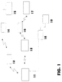
- FIG. 1 to 4 The invention is further illustrated by an embodiment with FIG. 1 to 4 described.
- the description below is an exemplary implementation of the invention.
- the description is pure exemplary character.
- FIG. 1 is a monitoring network, which consists of a central office 13, several Sub-centers 12, 14, 16, 18, a control unit 11 and the Surveillance camera units 15, 17 and 19 exist.
- control unit 11 shown in detail consists of a Display unit 21, a computing unit 22, input units 23, 24, 25 and a transmitting and receiving unit 26.
- the in FIG. 4 surveillance camera unit 17 shown in more detail consists of a camera unit 41, a positioning unit 44, a control unit 42 and a transmitting and receiving unit 43.
- the in FIG. 3 is shown in more detail in several areas divided up.
- the computing unit 22 controls and defines the display unit 21 on the display unit 21 a display area 31.
- this Display area 31 shows computing unit 22 one video signal at a time of the surveillance camera units 15, 17 or 19.
- About each one Control unit 23, 24, 25 can be any Surveillance camera units 15, 17, 19 selected and their current Video signal can be displayed.
- the leg units 23, 24, 25 are redundant.
- areas 32, 33, 34a, 34b are in the form of Scroll bars arranged on the edge of the display area 31.
- the surveillance camera unit 17 selected and their video signal is in the display area 31 of the Display unit 21 of the control unit 11 from the computing unit 22 of the Control unit 11 shown.
- the scroll bar 32 is at the bottom of the display area 31 Display unit 21 of the control unit 11 arranged and sets the horizontal Adjustment possibility of the positioning unit 44 of the Surveillance camera unit 17.
- the scroll bar 33 is on the left edge of the display area 31 of the display unit 21 of the control unit 11 arranged and provides the vertical adjustment of the Positioning unit 44 of the surveillance camera unit 17.
- Die Scroll bar 34a is on the right edge of the display area 31 Display unit 21 of the control unit 11 arranged and implemented in a visual Way the zoom option of the surveillance camera unit 17.
- Die Scroll bar 34b is also on the right edge of the display area 31 the display unit 21 of the control unit 11 arranged and implemented in visual way of focusing the surveillance camera unit 17.
- On the scroll bars 32, 33, 34a, 34b there are markings 35, 36, 37a, 37b arranged.
- marks 38 and 39 are in the Display area 31 of the display unit 21 of the control unit 11 is present.
- computing unit 22 at the same time displays multiple video signals from surveillance camera units.
- the camera unit 41 of the surveillance camera unit 17 detects one Part of the field of view to be monitored.
- the control unit 42 of the Surveillance camera unit 17 compresses the video signal of the Camera unit 41 of the surveillance camera unit 17 and the transmitting and Receiving unit 43 of surveillance camera unit 17 transmits this to the sub-center 16. This transmits the compressed video signal to the center 13, which the compressed video signal to the Control unit 11 transmitted.
- the transmit and receive Receiving unit 26 the compressed video signal and forwards it to the Computing unit 22 further.
- the computing unit 22 decompresses this Video signal and displays the video signal on the display unit 21 in Display area 31.
- To visualize the current settings of the Surveillance camera unit 17 transmits the control unit 42 of the Surveillance camera unit 17 after each change in the setting of the Positioning unit 44 of the surveillance camera unit 17 and / or the Zoomes and / or the focus of the camera unit 41 of the Surveillance camera unit 17 to the current setting data Control unit 11.
- the computing unit 22 evaluates this data and provides the current settings of the surveillance camera unit 17 via the Scroll bars 32, 33, 34a, 34b and the markings 35, 36, 37a, 37b in for is easily recognizable to the user.
- the scroll bar 32 with the marking 35 located on it represents the current positioning range of the surveillance camera unit 17, which can be defined within an entire positioning range, in the horizontal direction, regardless of how large the associated angle actually is.
- the marker 35 shows the current position of the surveillance camera unit 17 in the horizontal direction.
- the scroll bar 33 with the marking 36 located on it represents the positioning range of the surveillance camera unit 17, which can be defined within an entire positioning range, in the vertical direction, irrespective of how large the associated angle actually is.
- the marker 36 shows the current position of the surveillance camera unit 17 in the vertical direction.
- the scroll bar 34a with the marking 37a on it represents the entire adjustment range of the zoom setting of the surveillance camera unit 17, regardless of how large it is.
- the marking 37a shows the current setting of the zoom of the surveillance camera unit 17.
- the scroll bar 34b with the marking 37b located on it represents the entire adjustment range of the focusing of the surveillance camera unit 17, regardless of how large it is.
- the marking 37b shows the current setting of the focus of the surveillance camera unit 17.
- the computing unit 22 represents the marking 38 in the center of the display area 31. This visualizes the current center of the current scene captured by the surveillance camera unit 17.
- the computing unit 22 displays the marking 39 in the display area 31 of the display unit 21.
- the marking 39 is controlled by means of one of the input units 23, 24, 25 or more of the input units 23, 24, 25 and can be moved freely over the entire display area 31.
- the user of the control unit 11 receives the scene currently recorded by the surveillance camera unit 17 in the display area 31. If the orientation of the surveillance camera unit 17 is to be changed, the operator uses the input units 23, 24, 25 to control the marking 39 to that point on the display area 31 of the display unit 21 which is to be the new center of the scene. Once this selection has been made, it fixes the marking 39 via one of the input units 23, 24, 25 and the control unit 11 indicates the positioning of the surveillance camera unit 17 on the newly selected scene center. This is done in such a way that the computing unit 22 of the control unit 11 detects and calculates the distance between the markings 39 and 38 in the horizontal and vertical directions in the display area 31.
- the computing unit 22 detects the location values assigned to the markings 38 and 39 in the display area 31 and calculates the relative distance between the two markings. The calculation is carried out in relation to the image width and the image height of the display areas 31 of the display unit 21.
- the computing unit 22 of the control unit 11 compresses the determined distance data and transmits the distance data to the transmission and reception unit 26 of the control unit 11.
- the transmission and reception unit 26 transmits the data to the control center 13, which then sub-control center 16 and this conducts the compressed data to the surveillance camera unit 17. In the surveillance camera unit 17, these data are received by the transmitting and receiving unit 43, forwarded to the control unit 42 of the surveillance camera unit 17 and decompressed.
- the control unit 42 of the surveillance camera unit 17 calculates the absolute values for position control from these data and the current settings of the camera unit 41 of the surveillance camera unit 17, in particular the opening angle of the lens, and the positioning unit 44 of the surveillance camera unit 17.
- the control unit 42 of the surveillance camera unit 17 now controls the positioning unit 44 with the absolute data.
- the positioning unit 44 now moves the camera unit 41 into the new position at maximum speed.
- the video signals of the camera unit 41 continue to be in above described manner, transmitted to the control unit 11 and there on the Display unit 21 shown in the display area 31.
- the processing unit of the surveillance camera unit 17 calculates the computing unit 22 of the control unit 11 the new positioning of the markings 36 and 35 on the roller bars 33 and 32, based on the new position of the Surveillance camera unit 17.
- the user can use one of the input units 23, 24, 25 Positioning of the markings 35, 36 on the assigned Scroll bars 32, 33 move and thus the Surveillance camera unit 17 in a larger area than that Align display area 31.
- the mark 36 is on the scroll bar 33 moved all the way up, this evaluates the Computing unit 22 and transmits to surveillance camera unit 17 the command that the control unit 42 the positioning unit 44 with the Align camera unit 41 to the maximum vertical position still above.
- the marking 37a is moved on the scroll bar 34a.
- the marking 37a is selected via the input units 23, 24, 25 and postponed. In this way the zoom factor of the camera is increased or reduced.
- the image section is reduced or enlarged corresponding.
- the computing unit 22 detects the change in position the marking 37a on the scroll bar 34a to the previous position and determines a relative change in the marking to the previous one Position.
- This data about the relative change is transmitted by the Computing unit 22 via the transmission and reception unit 26 of the Control unit 11, via the center 13 and the sub-center 16 to the Surveillance camera unit 17.
- the transmitting and receiving unit 43 of the Surveillance camera unit 17 receives this data and guides it the control unit 42 of the surveillance camera unit 17.
- the Control unit 42 calculates the absolute data from the relative data Change the zoom of the camera unit 41 and represents the zoom of the Camera unit 41 to the new value.
- the Scroll bar 34b and mark 37b is on the Scroll bar 34b selected using one of the input units 23, 24, 25 and changed. The rest of the procedure corresponds to that for the zoom setting described procedure.
- the conversion of the relative data calculated by the computing unit 22 of the control unit 11 takes place in the control unit 42 of the surveillance camera unit 17 as follows:
- the relative data are calculated as the ratio of the current image width and image height of the display area 31 of the display unit 21 to the position of the marking 39 relative to the marking 38 on the display area 31 of the display unit 21.
- the width of the entire display area 31 is defined as 1, as is the height. If the marking 39 is changed, the new position of the marking 39 on the display area 31 of the display unit 21 of the control unit 11 can be specified in relation to the image width and height of the display area 31 and the marking 38 and in each case in a value range from -0.5 to +0.5 lie.
- the marking 39 is shifted from the marking 38 on the display area 31 to the top left onto a point of the display area 31 such that the ratio to the image width is -0.2 and the ratio to the image height is +0.3 by the computing unit 22 is determined, these values, namely -0.2 for the image width and +0.3 for the image height, are transmitted to the surveillance camera unit 17 as relative values.
- the control unit 42 of the surveillance camera unit 17 uses these relative data and the settings of the surveillance camera unit 17, in particular the opening angle of the lens, to calculate the new position values to which the positioning unit 44 of the surveillance camera unit 17 must be activated in order to assume the new position. In principle, this process also applies to zoom and focus.
- the track 32 is in shape a ring or an arc.
- this ring shows the Control unit 22 marks 35; the mark 35 is only on the Slidable ring. This creates the visual reference to the fact that the camera moves in a horizontal direction on a circular path because the Positioning unit 44 of surveillance camera unit 17 in a horizontal position Plane performs a circular movement and the camera unit 41 Surveillance camera unit 17 rotated and not linearly shifted.
- the scroll bar 33 and the scroll bar 32 applied a grid, which the absolute values of the Control shows in degrees-inclination angle. This is the user immediately clear at which point the camera is located.
- control unit 11 is replaced by a commercially available PC.
- the display unit 21 is formed by a screen monitor, the computing unit 22 is the CPU with memory, the transmitting and receiving unit 26 is implemented by a data interface and the input unit 23 by a mouse, the input unit 24 by a joystick and the input unit 25 by a commercially available one Keyboard. It is also conceivable to present the display unit 21 as a touch-sensitive screen, as a result of which the input units 23 to 25 can be dispensed with completely, since these are then directly integrated in the display unit 21.
- the camera control can also be used for automatic offender tracking.
- the user assigns an existing object, for example a person, to the marking 39 in the display area 31.
- the computing unit 22 analyzes the object, in particular the displayed shape of the object, and assigns the marking 39 to it, centered on the assigned object. If the object moves, this is determined by the computing unit 22.
- the computing unit 22 moves the marking 39 in accordance with the movement of the marked object. If the marking 39 moves, the computing unit 22 immediately calculates the relative change in the distance of the marking 39 from the marking 38 and transmits this data to the surveillance camera unit 17 in the manner described above.
- the surveillance camera unit guides the camera unit by means of the control unit 42 and the positioning unit 44 41 according to the object. In this way, the object is tracked continuously as long as it is in the area of the surveillance camera unit (visible area).
- the computing unit 22 recognizes the relative reduction in the size of the object and sends this relative data to the surveillance camera unit 17.
- the latter now controls the zoom and the focus based on the current settings of the camera unit 41 and the relative data, so that the object is displayed on the display area 31 in unchanged size and sharpness.
- the user able and detected by the surveillance camera unit 17 the scene shown in the display area 31 by means of one of the Input units 23, 24, 25 to zoom.
- the user defines one using one of the input units 23, 24, 25 rectangular area.
- the Computing unit 22 and the new display area 31 approaches, by giving the new relative data to the surveillance camera unit 17 transmitted.
- the control unit 42 of the surveillance camera unit 17 controls the camera unit 41 with the absolute setting data, calculated from the transferred relative data and the current settings of the Surveillance camera unit 17.
- the selected section is zoomed and shown in the display area 31 of the display unit 21.
- the Surveillance camera unit 15 wired to sub-center 14 connected.
- the sub-center 14 is, however, over a radio link with the Central 13 connected.
- the surveillance camera unit 19 is with the Sub-centers 18 connected via a line and the sub-center 18 is directly connected to the control unit 11.
- Surveillance camera unit to connect directly to the control unit 11. This causes the time delay in the transmission of the video signals the surveillance camera unit and in the transmission of the control data shortened. This makes real-time control easier.
- the Positioning unit 44 of surveillance camera unit 17 by a Swivel head or a so-called dome realized.
- the pan and tilt head and the dome have a serial interface Data transfer to.
- the Surveillance camera unit 17 equipped with an auto focus. Of the The focus automatically becomes the one currently being monitored by the surveillance camera unit 17 adapted scene.
- the Scroll bars 34a, 34b are automatically hidden if longer No changes in focus or zoom in the time period Surveillance camera unit 17 have been made.
Landscapes
- Engineering & Computer Science (AREA)
- Multimedia (AREA)
- Signal Processing (AREA)
- Human Computer Interaction (AREA)
- Closed-Circuit Television Systems (AREA)
- Studio Devices (AREA)
Abstract
Description
Das Überwachungsnetzwerk besteht beispielsweise aus einem Netzwerk von Zentrale und Unterzentralen einer Alarmanlage, einem Telefonnetzwerk auf digitaler Basis oder einem Kommunikationsnetz. Das Kommunikationsnetz kann sowohl ein analoges, als auch ein digitales Netz: sein
- FIG. 1
- eine schematische Darstellung eines Funkalarmnetzes mit Unterzentralen,
- FIG. 2
- einen schematischen Aufbau einer Steuereinheit;
- FIG. 3
- eine schematische Darstellung der Aufteilung der Bildoberfläche einer Anzeigeeinheit und
- FIG. 4
- einen schematischen Aufbau einer Überwachungskameraeinheit.
Die Bildlaufleiste 34b mit der auf ihr befindlichen Markierung 37b stellt den gesamten Verstellbereich der Fokusierung der Überwachungskameraeinheit 17 dar, unabhängig davon, wie groß dieser tatsächlich ist. Die Markierung 37b zeigt die aktuelle Einstellung des Fokus der Überwachungskameraeinheit 17.
Im weiteren stellt die Recheneinheit 22 die Markierung 38 im Zentrum des Anzeigebereiches 31 dar. Diese visualisiert den aktuellen Mittelpunkt der von der Überwachungskameraeinheit 17 erfaßten aktuellen Szene. Außerdem stellt die Recheneinheit 22 die Markierung 39 im Anzeigebereich 31 der Anzeigeeinheit 21 dar. Die Markierung 39 wird mittels einer der Eingabeeinheiten 23, 24, 25 oder mehrerer der Eingabeeinheiten 23, 24, 25 gesteuert und kann über den gesamten Anzeigebereich 31 frei verschoben werden.
Die Recheneinheit 22 der Steuereinheit 11 komprimiert die ermittelten Abstandsdaten und überträgt die Abstandsdaten an die Sende- und Empfangseinheit 26 der Steuereinheit 11. Die Sende- und Empfangseinheit 26 überträgt die Daten an die Zentrale 13, diese an die Unterzentrale 16 und diese leitet die komprimierten Daten an die Überwachungskameraeinheit 17 weiter. In der Überwachungskameraeinheit 17 werden diese Daten von der Sende- und Empfangseinheit 43 empfangen, an die Steuereinheit 42 der Überwachungskameraeinheit 17 weitergeleitet und entkomprimiert. Die Steuereinheit 42 der Überwachungskameraeinheit 17 errechnet aus diesen Daten und den aktuellen Einstellungen der Kameraeinheit 41 der Überwachungskameraeinheit 17, insbesondere des Öffnungswinkels des Objektivs, und der Positionierungseinheit 44 der Überwachungskameraeinheit 17 die Absolutwerte zur Positionssteuerung. Die Steuereinheit 42 der Überwachungskameraeinheit 17 steuert nunmehr die Positionierungseinheit 44 mit den Absolutdaten an. Die Positonierungseinheit 44 verfährt nun die Kameraeinheit 41 mit maximaler Geschwindigkeit in die neue Position.
Die Relativdaten werden als Verhältnis der aktuellen Bildbreite und Bildhöhe des Anzeigebereiches 31 der Anzeigeeinheit 21 zur Position der Markierung 39 gegenüber der Markierung 38 auf dem Anzeigebereich 31 der Anzeigeeinheit 21 errechnet. Die Breite des gesamten Anzeigebereiches 31 wird als 1 definiert, ebenso die Höhe. Wird die Markierung 39 verändert, so kann die neue Position der Markierung 39 auf dem Anzeigebereich 31 der Anzeigeeinheit 21 der Steuereinheit 11 im Verhältnis zur Bildbreite und Bildhöhe des Anzeigebereiches 31 und der Markierung 38 angegebene werden und jeweils in einem Wertebereich von -0,5 bis +0,5 liegen. Wird die Markierung 39 beispielsweise von der Markierung 38 ausgehend auf dem Anzeigebereich 31 derart nach links oben auf einen Punkt des Anzeigebereiches 31 verschoben, daß das Verhältnis zur Bildbreite mit -0,2 und das Verhältnis zur Bildhöhe mit +0,3 von der Recheneinheit 22 bestimmt wird, so werden diese Werte, nämlich -0,2 für die Bildbreite und +0,3 für die Bildhöhe als Relativwerte an die Überwachungskameraeinheit 17 übertragen. Die Steuereinheit 42 der Überwachungskameraeinheit 17 errechnet aus diesen Relativdaten und den Einstellungen der Überwachungskameraeinheit 17, insbeondere des Öffnungswinkels des Objektivs, die neuen Positionswerte, auf welche die Positionierungseinheit 44 der Überwachungskameraeinheit 17 angesteuert werden muß, um die neue Position einzunehmen. Dieser Ablauf gilt prinzipiell auch für Zoom und Fokus.
In einer modifizierten Ausgestaltung der Erfindung kann die Kamerasteuerung auch zur automatischen Täterverfolgung eingesetzt werden Hierzu weist der Benutzer der Markierung 39 im Anzeigebereich 31 ein vorhandenes Objekt, beispeilsweise eine Person, zu. Die Recheneinheit 22 analysiert das Objekt, insbesondere die angezeigte Form des Objektes und weist diesem, jeweils auf das zugewiesene Objekt zentriert, die Markierung 39 zu. Bewegt sich das Objekt, so wird dies von der Recheneinheit 22 ermittelt. Die Recheneinheit 22 bewegt die Markierung 39 entsprechend der Bewegung des markierten Objekts. Im Fall einer Bewegung der Markierung 39 errechnet die Recheneinheit 22 sofort die relative Veränderung des Abstandes der Markierung 39 von der Markierung 38 und überträgt diese Daten in oben beschriebener Weise an die Überwachungskameraeinheit 17. Die Überwachungskameraeinheit führt mittels der Steuereinheit 42 und der Positionierungseinheit 44 die Kameraeinheit 41 dem Objekt nach. Auf diese Weise wird das Objekt stetig verfolgt, so lange es im Bereich der Überwachungskameraeinheit (sichtbarer Bereich) ist. Entfernt sich das Objekt von der Überwachungskameraeinheit 17 und wird es auf dem Anzeigebereich 31 kleiner, so erkennt die Recheneinheit 22 die relative Verkleinerung des Objektes und übersendet diese Relativdaten an die Überwachungskameraeinheit 17. Diese regelt nun den Zoom und den Fokus anhand der aktuellen Einstellungen der Kameraeinheit 41 und den Relativdaten nach, sodaß das Objekt auf dem Anzeigebereich 31 in unveränderter Größe und Schärfe angezeigt wird.
Claims (15)
- Kamerasteuerung, insbesondere für Überwachungskameras, mit einer Steuereinheit (11), bestehend aus einer Recheneinheit (22), einer Anzeigeeinheit (21), Eingabeeinheiten (23, 24, 25) und einer Sende- und Empfangseinheit (26), wobei die Steuereinheit (11) mit einer Überwachungskameraeinheit (17), welche aus einer Sende- und Empfangseinheit (43), einer Steuereinheit (42), einer Positioniereinheit (44) und einer Kameraeinheit (41) besteht, über eine Übertragungsstecke verbunden ist,die Sende- und Empfangseinheit (43) der Überwachungskameraeinheit (17) das Videosignal der Kameraeinheit (41) der Überwachungskameraeinheit (17) über die Übertragungsstrecke zur Sende- und Empfangseinheit (26) der Steuereinheit (11) überträgt,die Recheneinheit (22) der Steuereinheit (11) das Videosignal auf der Anzeigeeinheit (21) der Steuereinheit (11) dargestellt,
dadurch gekennzeichnet,daß die Steuereinheit (11) anhand von Benutzereingaben über die Anzeigeeinheit (21) der Steuereinheit (11) relavie Positionsdaten zur Steuerung der Überwachungskameraeinheit (17) errechnet,daß die Steuereinheit (11) diese relativen Positionsdaten an die Überwachungskameraeinheit (17) überträgt und diese die relativen Positionsdaten in Absolutdaten zur Positionssteuerung umrechnet und die Positionssteuerung durchführt. - Kamerasteuerung nach Anspruch 1,
dadurch gekennzeichnet,daß die Recheneinheit (22) der Steuereinheit (11) die Anzeigeeinheit (21) der Steuereinheit (11) in Bereiche aufteilt,daß die Recheneinheit (22) der Steuereinheit (11) einen Anzeigebereich (31) auf der Anzeigeeinheit (21) der Steuereinheit (11) definiert, in welchem die Recheneinheit (22) der Steuereinheit (11) das Videosignal der Kameraeinheit (41) der Überwachungskameraeinheit (17) dargestellt,daß die Recheneinheit (22) der Steuereinheit (11) eine Markierung (38) im Anzeigebereich (31) der Anzeigeeinheit (21) der Steuereinheit (11) dargestellt, welche die Mitte der aktuellen Szenenaufnahme der Überwachungskameraeinheit (17) darstellt,daß die Recheneinheit (22) der Steuereinheit (11) eine weitere Markierung (39) im Anzeigebereich (31) der Anzeigeeinheit (21) der Steuereinheit (11) anzeigt,daß die Markierung (39) mittels jeweils einer der Eingabeeinheiten (23, 24, 25) über den Anzeigebereich (31) der Anzeigeeinheit (21) der Steuereinheit (11) verschiebbar ist,daß die Markierung (39) den neuen Ausrichtungspunkt der Überwachungskameraeinheit 17 darstellt,daß durch Aktivierung der Markierung (39) über eine der Eingabeeinheiten (23, 24, 25) die Recheneinheit (22) der Steuereinheit (11) den Abstand in horizontaler und vertikaler Richtung zwischen den Markierungen (38) und (39) auf dem Anzeigebereich (31) der Anzeigeeinheit (21) der Steuereinheit (11) errechnet,daß die Recheneinheit (22) der Steuereinheit (11) diese relativen Abstandsdaten an die Sende- und Empfangseinheit (26) der Steuereinheit (11) leitet und die Sende- und Empfangseinheit (26) der Steuereinheit (11) die relativen Abstandsdaten an die Überwachungskameraeinheit (17) überträgt,daß die Sende- und Empfangseinheit (43) der Überwachungskameraeinheit (17) die relativen Abstandsdaten empfängt und an die Steuereinheit (42) der Überwachungskameraeinheit (17) weiterleitetdaß die Steuereinheit (42) der Überwachungskameraeinheit (17) aus den relativen Abstandsdaten die Absolutdaten zur Steuerung der Positionierungseinheit (44) der Überwachungskameraeinheit (17), anhand der aktuellen Einstellungen der Kameraeinheit (41) der Überwachungskameraeinheit (17), insbesondere des Öffnungswinkels des Objektivs, und der Positionierungseinheit (44) der Überwachungskameraeinheit (17) errechnet unddaß die Steuereinheit (42) der Überwachungskameraeinheit (17) die Positionierungseinheit (44) der Überwachungskameraeinheit (17) mit den Absolutdaten ansteuert und die Kameraeinheit (41) der Überwachungskameraeinheit (17) auf die neue Position einstellt. - Kamerasteuerung nach Anspruch 2,
dadurch gekennzeichnet,daß die Recheneinheit (22) der Steuereinheit (11) auf der Anzeigeeinheit (21) der Steuereinheit (11) Bereiche (32, 33, 34a, 34b) anzeigt,daß die Recheneinheit (22) der Steuereinheit (11) diesen Bereichen Einstelldaten der Überwachungskameraeinheit (17) zuordnet und diese Einstelldaten visuell darstellt. - Kamerasteuerung nach Anspruch 3,
dadurch gekennzeichnet,daß die Recheneinheit (22) der Steuereinheit (11) auf der Anzeigeeinheit (21) der Steuereinheit (11) dem Bereich (32) den horizontalen Einstellungsbereich der Überwachungskameraeinheit (17) zuordnet,daß die Recheneinheit (22) der Steuereinheit (11) auf der Anzeigeeinheit (21) der Steuereinheit (11) dem Bereich (33) den vertikalen Einstellungsbereich der Überwachungskameraeinheit (17) zuordnet,daß die Recheneinheit (22) auf der Anzeigeeinheit (21) der Steuereinheit (11) dem Bereich (34a) den Zoombereich der Überwachungskameraeinheit (17) zuordnet unddaß die Recheneinheit (22) auf der Anzeigeeinheit (21) der Steuereinheit (11) dem Bereich (34b) die Einstellung des Fokus der Überwachungskameraeinheit (17) zuordnet. - Kamerasteuerung nach Anspruch 3 oder 4,
dadurch gekennzeichnet,daß die Recheneinheit (22) der Steuereinheit (11) auf den Bereichen (32, 33, 34a, 34b) der Anzeigeeinheit (21) der Steuereinheit (11) jeweils eine Markierung (35, 36, 37a, 37b) darstellt und daß die Recheneinheit (22) die Markierungen (35, 36, 37a, 37b) in den Bereichen (32, 33, 34a, 34b) der Anzeigeeinheit (21) der Steuereinheit (11) derart positioniert, daß diese die aktuellen relativen Positionen der Überwachungskameraeinheit (17) bzw. die aktuellen Einstellungen der Überwachungskameraeinheit (17), bezogen auf die Endstellungen der Überwachungskameraeinheit (17) visuallisieren. - Kamerasteuerung nach einem der Ansprüche 2 bis 5,
dadurch gekennzeichnet,daß die Recheneinheit (22) der Steuereinheit (11) die Bereiche (32, 33, 34a, 34b) der Anzeigeeinheit (21) der Steuereinheit (11) in Form von Bildlaufleisten darstellt. - Kamerasteuerung nach einem der Ansprüche 2 bis 6,
dadurch gekennzeichnet,daß die Steuereinheit (42) der Überwachungskameraeinheit (17) die Videosignale der Kameraeinheit (41) der Überwachungskameraeinheit (17) komprimiert und die Sende- und Empfangseinheit (43) der Überwachungskameraeinheit (17) die komprimierten Videosignale überträgt. - Kamerasteuerung nach einem der Ansprüche 2 bis 7,
dadurch gekennzeichnet,daß die Sende- und Empfangseinheit (26) der Steuereinheit (11) die von der Steuereinheit (42) der Überwachungskameraeinheit (17) komprimierten Videosignale der Kameraeinheit (41) der Überwachungskameraeinheit (17) empfängt und die Recheneinheit (22) der Steuereinheit (11) die komprimierten Videosignale entkomprimiert. - Kamerasteuerung nach einem der Ansprüche 2 bis 8,
dadurch gekennzeichnet,daß die Recheneinheit (22) der Steuereinheit (11) die Relativdaten zur Positionssteuerung komprimiert und die Sende- und Empfangseinheit (26) der Steuereinheit (11) diese komprimierten Daten sendet. - Kamerasteuerung nach einem der Ansprüche 2 bis 9,
dadurch gekennzeichnet,daß die Sende- und Empfangseinheit (43) der Überwachungskameraeinheit (17) die komprimierten Daten empfängt, die Steuereinheit (42) der Überwachungskameraeinheit (17) diese Relativdaten entkomprimiert und die Relativdaten anhand der aktuellen Einstellungen der Kameraeinheit (41) der Überwachungskameraeinheit (17) und der Positionierungseinheit (44) der Überwachungskameraeinheit (17) in Absolutdaten umrechnet und mit den Absolutdaten die Positionierungseinheit (44) der Überwachungskameraeinheit (17) die Kameraeinheit (41) der Überwachungskameraeinheit (17) ansteuert. - Kamerasteuerung nach einem der Ansprüche 7 oder 8,
dadurch gekennzeichnet,daß die Steuereinheit (42) der Überwachungskameraeinheit (17) und die Recheneinheit (22) der Steuereinheit (11) die Komprimierung und Entkomprimierung der Videosignale nach dem MPEG Standard durchführen. - Kamerasteuerung nach einem der Ansprüche 2 bis 11,
dadurch gekennzeichnet,daß die Recheneinheit (22) der Steuereinheit (11) die Markierung (39) mit einem im Anzeigebereich (31) der Anzeigeeinheit (21) der Steuereinheit (11) dargestellten Objekt verknüpft, das von der Markierung (39) markiert wird,daß die Recheneinheit (22) der Steuereinheit (11) das Objekt analysiert und die Markierung (39) dem Objekt nachführt, sobald das Objekt seine Position verändert, daß die Recheneinheit (22) der Steuereinheit (11) die Überwachungskameraeinheit 17 mit Relativdaten der Veränderung des Abstandes der Markierungen (38) und (39) ansteuert und die Steuereinheit (42) der Überwachungskameraeinheit 17 die Kameraeinheit (41) der Überwachungskameraeinheit 17 und die Positionierungseinheit (44) der Überwachungskameraeinheit 17 ansteuert, daß die Überwachungskameraeinheit 17 dem Objekt nachgeführt wird. - Kamerasteuerung nach einem der Ansprüche 2 bis 12,
dadurch gekennzeichnet,daß die Eingabeeinheiten (23, 24, 25) durch Trackballs, Computermäuse, Tastaturen, Grafiktabletts realisiert sind. - Kamerasteuerung nach Anspruch 2,
dadurch gekennzeichnet,daß die Recheneinheit (22) die relativen Abstandsdaten in Bezug zur Breite und Höhe des Anzeigebereichs (31) der Anzeigeeinheit (21) ermittelt. - Kamerasteuerung nach einem der Ansprüche 3 bis 6,
dadurch gekennzeichnet,daß die Recheneinheit (22) eine Aktivierung und Verschiebung einer der Markierungen (35, 36, 37a, 37b) auf der zugehörigen Bildlaufleisten (32, 33, 34a, 34b) erfaßt und daß die Recheneinheit (22) diese Verschiebung der Markierungen relativ zur vorherigen Position der Markierung auf der zugehörigen Bildlaufleiste erfaßt und die Relativdaten der Verschiebung, bezogen auf die Endstellungen, errechnet und an die Steuereinheit (42) der Überwachungskameraeinheit (17) überträgt.
Applications Claiming Priority (2)
| Application Number | Priority Date | Filing Date | Title |
|---|---|---|---|
| DE19811286A DE19811286C2 (de) | 1998-03-16 | 1998-03-16 | Kamerabewegungssteuerung |
| DE19811286 | 1998-03-16 |
Publications (2)
| Publication Number | Publication Date |
|---|---|
| EP0944259A2 true EP0944259A2 (de) | 1999-09-22 |
| EP0944259A3 EP0944259A3 (de) | 2000-08-02 |
Family
ID=7861017
Family Applications (1)
| Application Number | Title | Priority Date | Filing Date |
|---|---|---|---|
| EP99104240A Withdrawn EP0944259A3 (de) | 1998-03-16 | 1999-03-03 | Kamerabewegungssteuerung |
Country Status (3)
| Country | Link |
|---|---|
| EP (1) | EP0944259A3 (de) |
| JP (1) | JPH11331824A (de) |
| DE (1) | DE19811286C2 (de) |
Cited By (2)
| Publication number | Priority date | Publication date | Assignee | Title |
|---|---|---|---|---|
| EP1274231A3 (de) * | 2001-07-06 | 2004-06-30 | plettac AG | Verfahren und Vorrichtung zur Steuerung von Schwenk-Neige-Bewegungen einer Kamera |
| EP1696383A3 (de) * | 2005-02-25 | 2006-10-11 | Psion Teklogix Systems Inc. | Automatische Detektion und Korrektur von Perspektivenverzerrung für Dokumentabbildungen |
Families Citing this family (5)
| Publication number | Priority date | Publication date | Assignee | Title |
|---|---|---|---|---|
| DE19958634A1 (de) * | 1999-12-04 | 2001-06-21 | Alcatel Sa | Verfahren zum Erkennen von Hindernissen auf Bahnstrecken |
| DE10033652A1 (de) * | 2000-07-11 | 2002-01-24 | Messer Griesheim Gmbh | Überwachungssystem und Verfahren zur fernüberwachten Kontrolle von Lagerbeständen |
| DE20208160U1 (de) | 2002-05-24 | 2002-09-12 | Hwg Telekommunikations Systeme | Überwachungskamera mit Funksender |
| DE10341125B4 (de) * | 2003-09-06 | 2005-09-01 | Jeromin, Günter E., Prof. Dr. | Beobachtungsgerät |
| CN114670981B (zh) * | 2022-03-24 | 2023-05-26 | 阿里云计算有限公司 | 用于控制相机的方法和装置 |
Family Cites Families (9)
| Publication number | Priority date | Publication date | Assignee | Title |
|---|---|---|---|---|
| US4720805A (en) * | 1985-12-10 | 1988-01-19 | Vye Scott R | Computerized control system for the pan and tilt functions of a motorized camera head |
| US4992866A (en) * | 1989-06-29 | 1991-02-12 | Morgan Jack B | Camera selection and positioning system and method |
| US5164827A (en) * | 1991-08-22 | 1992-11-17 | Sensormatic Electronics Corporation | Surveillance system with master camera control of slave cameras |
| DE4233137C1 (de) * | 1992-10-02 | 1994-01-05 | Ibm | Verfahren und Vorrichtung zur Steuerung einer Kamera |
| JP3382276B2 (ja) * | 1993-01-07 | 2003-03-04 | キヤノン株式会社 | 電子機器及びその制御方法 |
| US5473369A (en) * | 1993-02-25 | 1995-12-05 | Sony Corporation | Object tracking apparatus |
| JPH09506217A (ja) * | 1993-10-20 | 1997-06-17 | ヴィデオコンファレンスィング システムズ インコーポレイテッド | 適応型テレビ会議システム |
| CA2155719C (en) * | 1994-11-22 | 2005-11-01 | Terry Laurence Glatt | Video surveillance system with pilot and slave cameras |
| US6768563B1 (en) * | 1995-02-24 | 2004-07-27 | Canon Kabushiki Kaisha | Image input system |
-
1998
- 1998-03-16 DE DE19811286A patent/DE19811286C2/de not_active Expired - Lifetime
-
1999
- 1999-03-03 EP EP99104240A patent/EP0944259A3/de not_active Withdrawn
- 1999-03-15 JP JP11068106A patent/JPH11331824A/ja not_active Withdrawn
Cited By (2)
| Publication number | Priority date | Publication date | Assignee | Title |
|---|---|---|---|---|
| EP1274231A3 (de) * | 2001-07-06 | 2004-06-30 | plettac AG | Verfahren und Vorrichtung zur Steuerung von Schwenk-Neige-Bewegungen einer Kamera |
| EP1696383A3 (de) * | 2005-02-25 | 2006-10-11 | Psion Teklogix Systems Inc. | Automatische Detektion und Korrektur von Perspektivenverzerrung für Dokumentabbildungen |
Also Published As
| Publication number | Publication date |
|---|---|
| DE19811286C2 (de) | 2003-06-26 |
| JPH11331824A (ja) | 1999-11-30 |
| EP0944259A3 (de) | 2000-08-02 |
| DE19811286A1 (de) | 1999-09-23 |
Similar Documents
| Publication | Publication Date | Title |
|---|---|---|
| DE69835185T2 (de) | Kamerasteuersystem | |
| DE69332282T2 (de) | Verfahren und Gerät für Benutzersteuerung durch Ermittlung der nächsten Prozesszustände aus dem aktuellen Zustand und durch visuelle Darstellung der abgeleiteten nächsten Zustände | |
| DE69216005T2 (de) | Fernseh-Überwachungsanlage, bei der Nebenkameras durch die Hauptkamera gesteuert werden | |
| DE69727095T2 (de) | Kamerasteuerung durch Steuerung eines Kamerasymbols auf einem Hintergrundbild | |
| DE60001631T2 (de) | Interaktives anzeigesystem | |
| EP3985964B1 (de) | Fernsteuereinrichtung für eine bewegtbildkamera | |
| DE102015016848A1 (de) | System zur zentralen Steuerung von ein oder mehreren Kranen | |
| DE19811286C2 (de) | Kamerabewegungssteuerung | |
| WO2007104367A1 (de) | Video-überwachungssystem | |
| DE10012629A1 (de) | Ferngesteuertes Schwenkkopfsystem | |
| DE69418111T2 (de) | Steuergerät und Steuerverfahren für Bildeingabevorrichtung | |
| DE10132929B4 (de) | Verfahren und Vorrichtung zur Steuerung von Schwenk-Neige-Bewegungen einer Kamera | |
| EP1936583B1 (de) | Flughafenverkehrsinformations-Anzeigesystem | |
| EP2898666B1 (de) | Client-einrichtung zur darstellung von kamerabildern einer steuerbaren kamera, verfahren, computerprogramm sowie überwachungssystem mit der client-einrichtung | |
| EP1434184B1 (de) | Steuerung eines Multikamera-Systems | |
| WO2006032552A1 (de) | Folgekamerasteuerung | |
| EP1296213A1 (de) | Verfahren und Vorrichtung zum Führen eines unbemannten Fluggerätes | |
| EP0851448B1 (de) | Gestaltbare Bedienungseinheit zur Steuerung elektronischer Geräte | |
| EP2424225B1 (de) | Bilderfassungssystem und Verfahren zum Erfassen eines Objekts | |
| EP1460383B1 (de) | Kameravorrichtung für ein Fahrzeug | |
| EP3826954B1 (de) | Fernsteuerungsanordnung, verfahren zum betrieb der fernsteuerungsanordnung, und computerprogrammprodukt | |
| DE9421861U1 (de) | Vorrichtung zur Überwachung von zu sichernden Bereichen | |
| DE10141521C1 (de) | Darstellung von Anwenderinformationen | |
| DE102023206951A1 (de) | Verfahren zum Betreiben eines Kransystems und Kamerasystem | |
| DE10210949A1 (de) | Vorrichtung und Verfahren zur Überwachung von Arealen |
Legal Events
| Date | Code | Title | Description |
|---|---|---|---|
| PUAI | Public reference made under article 153(3) epc to a published international application that has entered the european phase |
Free format text: ORIGINAL CODE: 0009012 |
|
| AK | Designated contracting states |
Kind code of ref document: A2 Designated state(s): AT BE CH DE DK ES FI FR GB GR IE IT LI NL PT SE |
|
| AX | Request for extension of the european patent |
Free format text: AL;LT;LV;MK;RO;SI |
|
| PUAL | Search report despatched |
Free format text: ORIGINAL CODE: 0009013 |
|
| AK | Designated contracting states |
Kind code of ref document: A3 Designated state(s): AT BE CH CY DE DK ES FI FR GB GR IE IT LI LU MC NL PT SE |
|
| AX | Request for extension of the european patent |
Free format text: AL;LT;LV;MK;RO;SI |
|
| 17P | Request for examination filed |
Effective date: 20010108 |
|
| AKX | Designation fees paid |
Free format text: AT BE CH DE DK ES FI FR GB GR IE IT LI NL PT SE |
|
| RAP1 | Party data changed (applicant data changed or rights of an application transferred) |
Owner name: FUNKWERK PLETTAC ELECTRONIC GMBH |
|
| 17Q | First examination report despatched |
Effective date: 20050203 |
|
| GRAP | Despatch of communication of intention to grant a patent |
Free format text: ORIGINAL CODE: EPIDOSNIGR1 |
|
| STAA | Information on the status of an ep patent application or granted ep patent |
Free format text: STATUS: THE APPLICATION IS DEEMED TO BE WITHDRAWN |
|
| 18D | Application deemed to be withdrawn |
Effective date: 20060210 |