EP0944542B1 - Wickelmaschine für ein flaches endloses element zur bildung von bahnwickeln - Google Patents
Wickelmaschine für ein flaches endloses element zur bildung von bahnwickeln Download PDFInfo
- Publication number
- EP0944542B1 EP0944542B1 EP97951329A EP97951329A EP0944542B1 EP 0944542 B1 EP0944542 B1 EP 0944542B1 EP 97951329 A EP97951329 A EP 97951329A EP 97951329 A EP97951329 A EP 97951329A EP 0944542 B1 EP0944542 B1 EP 0944542B1
- Authority
- EP
- European Patent Office
- Prior art keywords
- sheet
- cutting
- spindle
- tension
- contact
- Prior art date
- Legal status (The legal status is an assumption and is not a legal conclusion. Google has not performed a legal analysis and makes no representation as to the accuracy of the status listed.)
- Expired - Lifetime
Links
- 238000005520 cutting process Methods 0.000 claims abstract description 51
- 238000011144 upstream manufacturing Methods 0.000 claims abstract description 5
- 238000004804 winding Methods 0.000 claims description 38
- 238000006073 displacement reaction Methods 0.000 claims 1
- 238000004519 manufacturing process Methods 0.000 description 17
- 238000005259 measurement Methods 0.000 description 5
- 238000000034 method Methods 0.000 description 5
- 238000002242 deionisation method Methods 0.000 description 3
- -1 plates Substances 0.000 description 3
- 230000008569 process Effects 0.000 description 3
- 230000008859 change Effects 0.000 description 2
- 238000010924 continuous production Methods 0.000 description 2
- 239000004033 plastic Substances 0.000 description 2
- 229920003023 plastic Polymers 0.000 description 2
- 239000002985 plastic film Substances 0.000 description 2
- 239000004698 Polyethylene Substances 0.000 description 1
- 239000004743 Polypropylene Substances 0.000 description 1
- 239000002390 adhesive tape Substances 0.000 description 1
- 238000013459 approach Methods 0.000 description 1
- 239000004744 fabric Substances 0.000 description 1
- 239000010408 film Substances 0.000 description 1
- 230000006872 improvement Effects 0.000 description 1
- 239000007788 liquid Substances 0.000 description 1
- 238000012423 maintenance Methods 0.000 description 1
- 239000000463 material Substances 0.000 description 1
- 239000002184 metal Substances 0.000 description 1
- 238000012986 modification Methods 0.000 description 1
- 230000004048 modification Effects 0.000 description 1
- 230000035515 penetration Effects 0.000 description 1
- 229920006255 plastic film Polymers 0.000 description 1
- 229920000728 polyester Polymers 0.000 description 1
- 229920000573 polyethylene Polymers 0.000 description 1
- 229920001155 polypropylene Polymers 0.000 description 1
- 229920000915 polyvinyl chloride Polymers 0.000 description 1
- 238000012545 processing Methods 0.000 description 1
- 230000000750 progressive effect Effects 0.000 description 1
- 239000010409 thin film Substances 0.000 description 1
- 238000012549 training Methods 0.000 description 1
- 230000009466 transformation Effects 0.000 description 1
Images


Classifications
-
- B—PERFORMING OPERATIONS; TRANSPORTING
- B65—CONVEYING; PACKING; STORING; HANDLING THIN OR FILAMENTARY MATERIAL
- B65H—HANDLING THIN OR FILAMENTARY MATERIAL, e.g. SHEETS, WEBS, CABLES
- B65H19/00—Changing the web roll
- B65H19/22—Changing the web roll in winding mechanisms or in connection with winding operations
- B65H19/2207—Changing the web roll in winding mechanisms or in connection with winding operations the web roll being driven by a winding mechanism of the centre or core drive type
- B65H19/2215—Turret-type with two roll supports
-
- B—PERFORMING OPERATIONS; TRANSPORTING
- B65—CONVEYING; PACKING; STORING; HANDLING THIN OR FILAMENTARY MATERIAL
- B65H—HANDLING THIN OR FILAMENTARY MATERIAL, e.g. SHEETS, WEBS, CABLES
- B65H19/00—Changing the web roll
- B65H19/22—Changing the web roll in winding mechanisms or in connection with winding operations
- B65H19/28—Attaching the leading end of the web to the replacement web-roll core or spindle
-
- B—PERFORMING OPERATIONS; TRANSPORTING
- B65—CONVEYING; PACKING; STORING; HANDLING THIN OR FILAMENTARY MATERIAL
- B65H—HANDLING THIN OR FILAMENTARY MATERIAL, e.g. SHEETS, WEBS, CABLES
- B65H23/00—Registering, tensioning, smoothing or guiding webs
- B65H23/04—Registering, tensioning, smoothing or guiding webs longitudinally
- B65H23/18—Registering, tensioning, smoothing or guiding webs longitudinally by controlling or regulating the web-advancing mechanism, e.g. mechanism acting on the running web
- B65H23/195—Registering, tensioning, smoothing or guiding webs longitudinally by controlling or regulating the web-advancing mechanism, e.g. mechanism acting on the running web in winding mechanisms or in connection with winding operations
-
- B—PERFORMING OPERATIONS; TRANSPORTING
- B65—CONVEYING; PACKING; STORING; HANDLING THIN OR FILAMENTARY MATERIAL
- B65H—HANDLING THIN OR FILAMENTARY MATERIAL, e.g. SHEETS, WEBS, CABLES
- B65H2301/00—Handling processes for sheets or webs
- B65H2301/40—Type of handling process
- B65H2301/41—Winding, unwinding
- B65H2301/414—Winding
- B65H2301/41419—Starting winding process
- B65H2301/41421—Starting winding process involving electrostatic means
-
- B—PERFORMING OPERATIONS; TRANSPORTING
- B65—CONVEYING; PACKING; STORING; HANDLING THIN OR FILAMENTARY MATERIAL
- B65H—HANDLING THIN OR FILAMENTARY MATERIAL, e.g. SHEETS, WEBS, CABLES
- B65H2301/00—Handling processes for sheets or webs
- B65H2301/50—Auxiliary process performed during handling process
- B65H2301/51—Modifying a characteristic of handled material
- B65H2301/515—Cutting handled material
- B65H2301/5151—Cutting handled material transversally to feeding direction
-
- B—PERFORMING OPERATIONS; TRANSPORTING
- B65—CONVEYING; PACKING; STORING; HANDLING THIN OR FILAMENTARY MATERIAL
- B65H—HANDLING THIN OR FILAMENTARY MATERIAL, e.g. SHEETS, WEBS, CABLES
- B65H2408/00—Specific machines
- B65H2408/20—Specific machines for handling web(s)
- B65H2408/23—Winding machines
- B65H2408/231—Turret winders
- B65H2408/2315—Turret winders specified by number of arms
- B65H2408/23152—Turret winders specified by number of arms with two arms
-
- Y—GENERAL TAGGING OF NEW TECHNOLOGICAL DEVELOPMENTS; GENERAL TAGGING OF CROSS-SECTIONAL TECHNOLOGIES SPANNING OVER SEVERAL SECTIONS OF THE IPC; TECHNICAL SUBJECTS COVERED BY FORMER USPC CROSS-REFERENCE ART COLLECTIONS [XRACs] AND DIGESTS
- Y10—TECHNICAL SUBJECTS COVERED BY FORMER USPC
- Y10S—TECHNICAL SUBJECTS COVERED BY FORMER USPC CROSS-REFERENCE ART COLLECTIONS [XRACs] AND DIGESTS
- Y10S242/00—Winding, tensioning, or guiding
- Y10S242/906—Static charger or discharger
Definitions
- the present invention relates to a winding machine, or winder, of a continuous flat element to form coils.
- Winders are used in a very large number of branches of industry where the machines and processes used result in the continuous production of a flat element more or less large width and variable thickness.
- the flat elements produced by the production lines must be wound up so that they can be easily transported to further processing steps.
- Winders for this type of application have all a number of common elements which are:
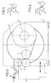
- rewinder pins (1) are each provided with their device drive, and are mounted integrally on a rotary assembly called barrel (2) mounted on a frame (3).
- Each spindle (1) with its associated drive device receives at a given time the sheet (F) arriving continuously from the line of production, the drive system and its regulation delivering on the spindle the torque necessary for the sheet to be driven at speed desired and under the desired tension.
- the devices necessary for torque regulation are either dancer rollers or electronic voltage gauge located upstream of the spindle (1) and loaded continuously measure the tension of the sheet (F) so as to control the motor according to a winding law established in advance.
- the spindle itself is not driven, but it is a contact roller (4), itself driven, which delivers the necessary torque to the winding.
- this device is made up depends a lot on the how the elements that precede the whole are made up barrel / pin and whose function is to feed the product to be wound up convenient way while allowing regulation of the devices drive.
- These training devices generally consist of one or more cylinders each fulfilling well-defined functions and which are generally integral with a mobile carriage (5) allowing the cylinders indicated above to maintain a geometric arrangement constant as the diameter of the coil increases as winding measurement.
- FIG. 2 represents a variant of the machine of FIG. 1.
- Such machines are used when winding wide plastic sheets (up to 8 and 9 meters wide), for thin films with a thickness between 5 and 100 microns, but generally between 10 and 30, and at speeds of several hundreds of meters per minute.
- a second cylinder called contact cylinder (4)
- contact winding Two types windings are frequently used, the so-called contact winding, as shown in Figure 3, during which the contact cylinder exerts a light pressure on the reel in the process of winding, so that evacuate the air which would otherwise risk being trapped in large quantities in the reel due to the winding speed of the sheet, and the so-called "gap" winding, as shown in FIG. 4, in which the contact cylinder (4) is at a short distance and is maintained at near constant to the winding point.
- This type of winding is preferred when the speed is low because the risk of air entrapment is then low, or when the thickness of the product to be wound up is not very regular and contact type operation would be likely damage the rolled up product.
- the horizontally fed sheet may pass either above or below the set of mounted cylinders on the cart. This choice has very important consequences for the nature of the cutting system.
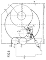
- Figure 5 shows a reel equipped with a cutting.
- This cutting device must be implemented automatically when the cut is desired, the cut in front be insured in such a way that it disturbs the least possible unwinding of the sheet, the cutting point to be chosen in such a way so that the sheet, immediately after cutting, or in the case a progressive cut, the point corresponding to the beginning of the cut out, can easily be wrapped around the spindle (1) to be re-supplied so as to ensure the starting of the coil.
- the cutting device provides for tying rollers (9) bringing the sheet (F) close to the spindle (1) to feed.
- the device must provide, in addition to the cutting system by fixed blade (10) or by movable knives, means for guiding the sheet against the new spindle and which are either air jets or brush systems, or so-called electrostatic systems (11) generating the surface of the sheet of electrostatic charges ensuring the contact of the sheet cut with the metal pin to be re-fed.
- means for guiding the sheet against the new spindle which are either air jets or brush systems, or so-called electrostatic systems (11) generating the surface of the sheet of electrostatic charges ensuring the contact of the sheet cut with the metal pin to be re-fed.
- adhesive tapes or possibly jets of vaporized liquid are used to ensure reliable contact.
- the multiplicity of functions to be fulfilled by the cutting makes it generally complex, heavy and its functioning is ensured only on condition that the arrangement in the space of all the elements that make up the spindle to re-supply the sheet and the cutting system itself are fine defined.
- This aspect can be further increased if, what happens unfortunately sometimes a second break occurs again before the new coil has reached a diameter economically valid. In this case, it is the entire production corresponding to two coils started, but insufficiently completed, which is lost.
- the object of the invention is to provide a winding machine having a device to avoid production losses by allowing automatic cutting of a sheet at the end of winding of a coil and for its winding on an empty spindle intended for support another coil, and also allowing a start not on an empty spindle, as is the case with existing devices, but on a coil already started, whatever the diameter of the coil considered.
- the cutting device being located between the measuring cylinder of tension and the contact cylinder, i.e. before the point winding on the spindle or on the coil to be re-supplied, the position of the cutting sheet is perfectly defined, whatever the diameter of the spindle or spool on which the sheet is to be fed.
- the cylinders of voltage and contact measurement are motorized.
- the sheet is therefore perfectly controlled in tension of the made of the proximity of the tension cylinder, and is well pressed against the spindle or the coil to be re-supplied by the contact cylinder.
- the machine is equipped with means for commands which cause, before cutting, an increase in the sheet tension in the area between the measuring cylinder tension and the winding point by acting on the drive speed of the tension measuring spindle and / or cylinder, and an increase the contact cylinder application pressure on the spindle or coil.
- the cutting and winding conditions on the new support are perfectly filled thanks to the increased tension of the sheet and increasing the application pressure of the cylinder contact against the spindle or the coil to be re-supplied.
- the leaf presents itself thus perfectly flat with a slight overpressure conducive to good penetration of knives and a clean and quick cut.
- the point cut driven by the leaf's own speed, penetrates very quickly between the two cylinders.
- a deionization device which is activated just before cutting, to remove electrical charges from the surface of the contact cylinder.
- the cutting device has, near the knife guide, an ionization bar extending transversely to the sheet, activated just before cutting to electrostatically charge the sheet and create an attraction between the cut out part and the winding spindle.
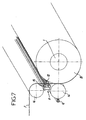
- Figure 6 shows a reel of the same type as those described above, and in which the same elements are designated by the same references as above.
- the carriage 5 is equipped with a horizontal cylinder 16 for measuring tension, on which sheet F arrives substantially horizontal.
- the carriage 5 also carries a cylinder horizontal 14, which is a contact cylinder with the coil B formed on pin 1 or with pin 1, before forming the coil.
- the cylinder 14 is parallel to the cylinder 16, arranged below the latter, and substantially vertical to this cylinder.
- a cutting device 11 This cutting device comprises a rail on which are movable mounted knives 12 for cutting the sheet.
- an ionization bar 15 is intended to be activated just before cutting to load electrostatically sheet F and create an attraction between the part cut from it and the winding pin 1 or the coil B according to the case.
- a deionization bar 13 which is activated just before cutting, to remove electrical charges from the surface of the contact cylinder.
- the cutting is carried out on a taut surface, allowing a clean cut, the end cut tending, taking into account the speed of the sheet, the proximity to cylinder 14 and pin 1, and electrical charges cylinder 14 and sheet, to be wound on the spindle or on the coil, insofar as it involves re-supplying a coil already started.
- the invention provides a great improvement to the existing technique by providing a machine winding of a continuous element to constitute coils, allowing continuous cutting of the winding, and allowing also to make a start of winding, not only on a empty spindle, but also on a spool on which the winding has already started.
Landscapes
- Replacement Of Web Rolls (AREA)
- Winding Of Webs (AREA)
- Controlling Rewinding, Feeding, Winding, Or Abnormalities Of Webs (AREA)
- Auxiliary Devices For And Details Of Packaging Control (AREA)
- Windings For Motors And Generators (AREA)
Claims (7)
- Maschine zum Aufwickeln eines durchgehenden Elementes in Form eines Flächenkörpers zur Ausbildung von Spulen, die mit einer Schneidvorrichtung für den von einer Rolle zu einer anderen übergehenden Flächenkörper ausgestattet ist, von der Bauart, die einen Rahmen (3) aufweist, auf dem eine Trommel (2) gelagert ist, die mit mindestens zwei Dornen (1) ausgestattet ist, die parallel angeordnet und jeweils an an sich bekannte Drehantriebseinrichtungen angeschlossen sind, wobei die Drehung der Trommel zugleich den Austrag einer vollen Spule und die Zuführung eines leeren Dornes zur Aufwickelstation ermöglicht, und einen senkrecht zur Achse der Dorne verfahrbaren Schlitten (5) aufweist, der seinerseits Zylinder für die Versorgung der Maschine mit einem aufzuwickelnden Flächenkörper trägt, wobei der Schlitten (5) einen Zylinder (16) für die Messung der Spannung aufweist, bei dem der Flächenkörper (5) im wesentlichen in der Horizontalen ankommt, und wobei eine Schneidvorrichtung (11) stromaufwärts von dem Aufwickelpunkt an dem Dorn oder der auszubildenden Spule vorgesehen ist,
dadurch gekennzeichnet, daß ein Zylinder (14) für die Herstellung eines Kontaktes mit der Spule auf dem Schlitten (5) vorgesehen ist, und zwar unterhalb des Zylinders (16) für die Messung der Spannung, im wesentlichen vertikal zu diesem,
und daß die Schneidvorrichtung (11) zwischen den beiden Zylindern (16, 14) für die Messung der Spannung bzw. für die Kontaktherstellung angeordnet ist. - Maschine nach Anspruch 1,
dadurch gekennzeichnet, daß die Zylinder (16, 14) für die Messung der Spannung bzw. für die Kontaktherstellung mit Motoren versehen sind. - Maschine nach Anspruch 1 oder 2,
dadurch gekennzeichnet, daß die Schneidvorrichtung bewegliche Messer (12) aufweist, die quer zur Vorschubrichtung des Flächenkörpers verschiebbar sind. - Maschine nach Anspruch 3,
dadurch gekennzeichnet, daß die Verschiebungsgeschwindigkeit der beweglichen Messer (12) im wesentlichen gleich der Durchlaufgeschwindigkeit des Flächenkörpers (F) ist. - Maschine nach einem der Ansprüche 1 bis 4,
dadurch gekennzeichnet, daß ihre Steuereinrichtungen vor dem Schneidvorgang eine Vergrößerung der Spannung des Flächenkörpers in der Zone bewirken, die sich zwischen dem Zylinder (16) für die Messung der Spannung und dem Aufwickelpunkt befindet, indem sie auf die Antriebsgeschwindigkeit des Dornes (1) und/oder des Zylinders (16) für die Messung der Spannung einwirken, sowie eine Vergrößerung des Anpreßdruckes des Zylinders (14) für die Kontaktherstellung gegen den Dorn (1) oder die Spule bewirken. - Maschine nach einem der Ansprüche 1 bis 5,
dadurch gekennzeichnet, daß sie in der Nähe des Zylinders (14) für die Kontaktherstellung eine Entionisierungseinrichtung (13) aufweist, die unmittelbar vor dem Schneidvorgang aktiviert wird, um elektrische Ladungen auf der Oberfläche des Zylinders für die Kontaktherstellung zu beseitigen. - Maschine nach einem der Ansprüche 1 bis 6,
dadurch gekennzeichnet, daß die Schneidvorrichtung (11) in der Nähe der Führung der Messer (12) eine Ionisierungsstange (15) aufweist, die sich quer zu dem Flächenkörper erstreckt und die unmittelbar vor dem Schneidvorgang aktiviert wird, um den Flächenkörper elektrostatisch aufzuladen und eine Anziehung zwischen dem abgeschnittenen Teil und dem Aufwickeldorn (1) zu erzeugen.
Applications Claiming Priority (3)
| Application Number | Priority Date | Filing Date | Title |
|---|---|---|---|
| FR9615527A FR2757141B1 (fr) | 1996-12-12 | 1996-12-12 | Machine d'enroulement d'un element plat continu pour former des bobines |
| FR9615527 | 1996-12-12 | ||
| PCT/FR1997/002292 WO1998025844A1 (fr) | 1996-12-12 | 1997-12-12 | Machine d'enroulement d'un element plat continu pour former des bobines |
Publications (2)
| Publication Number | Publication Date |
|---|---|
| EP0944542A1 EP0944542A1 (de) | 1999-09-29 |
| EP0944542B1 true EP0944542B1 (de) | 2002-06-05 |
Family
ID=9498778
Family Applications (1)
| Application Number | Title | Priority Date | Filing Date |
|---|---|---|---|
| EP97951329A Expired - Lifetime EP0944542B1 (de) | 1996-12-12 | 1997-12-12 | Wickelmaschine für ein flaches endloses element zur bildung von bahnwickeln |
Country Status (7)
| Country | Link |
|---|---|
| US (1) | US6308908B1 (de) |
| EP (1) | EP0944542B1 (de) |
| JP (1) | JP4031050B2 (de) |
| AT (1) | ATE218491T1 (de) |
| DE (1) | DE69713137T2 (de) |
| FR (1) | FR2757141B1 (de) |
| WO (1) | WO1998025844A1 (de) |
Families Citing this family (11)
| Publication number | Priority date | Publication date | Assignee | Title |
|---|---|---|---|---|
| GB2379924A (en) * | 2001-09-22 | 2003-03-26 | Ashe Controls Ltd | Winding method and apparatus |
| US7055776B2 (en) * | 2001-10-24 | 2006-06-06 | Windmoeller And Hoelscher | Device for continuous winding of webs |
| US8757533B2 (en) * | 2002-02-28 | 2014-06-24 | Kimberly-Clark Worldwide, Inc. | Center/surface rewinder and winder |
| US6908525B2 (en) * | 2002-06-11 | 2005-06-21 | 3M Innovative Properties Company | Apparatus for forming a roll of contaminant removal tape and methods of forming rolls of contaminant removal tape |
| ES2274150T3 (es) * | 2003-08-07 | 2007-05-16 | REIFENHAUSER GMBH & CO. MASCHINENFABRIK | Dispositivo de corte transversal para una banda de material. |
| US7655542B2 (en) * | 2006-06-23 | 2010-02-02 | Applied Materials, Inc. | Methods and apparatus for depositing a microcrystalline silicon film for photovoltaic device |
| FR2922810B1 (fr) | 2007-10-24 | 2013-05-31 | Darlet Marchante Technologie | Procede d'etirage d'un film en matiere synthetique se presentant sous la forme d'une bande allongee. |
| CN102248751A (zh) * | 2011-05-09 | 2011-11-23 | 广东汕樟轻工机械有限公司 | 一种直线运动贴近辊式自动裁刀机构 |
| DE102015221919A1 (de) * | 2015-11-09 | 2017-05-11 | Koenig & Bauer Ag | Wickelvorrichtung für bahnförmiges Material und Verfahren zum Einziehen zumindest einer Materialbahn in zumindest eine Wickelvorrichtung |
| CN107117484B (zh) * | 2017-05-06 | 2018-12-11 | 南京航空航天大学 | 一种自动切换的卷棉装置及操作方法 |
| CN120081234B (zh) * | 2024-08-02 | 2025-11-25 | 苏州金纬片板膜智能装备有限公司 | 落地式大卷径全自动收卷设备 |
Family Cites Families (23)
| Publication number | Priority date | Publication date | Assignee | Title |
|---|---|---|---|---|
| US2969930A (en) * | 1958-09-22 | 1961-01-31 | Mercury Engineering Corp | Continuous rewinder for web material |
| US3383062A (en) * | 1965-06-30 | 1968-05-14 | Black Clawson Co | Method and apparatus for continuously winding web material with constant tension |
| DE1774101B1 (de) * | 1968-04-08 | 1971-11-04 | Weser Lenze Stahlkontor | Vorrichtung zum rollenwechsel und querschneiden von mit hoher geschwindigkeit laufenden bahnen bei mehrfach wickel maschinen |
| JPS5134545B1 (de) * | 1970-12-29 | 1976-09-27 | ||
| DE2218939A1 (de) * | 1972-04-19 | 1973-10-31 | Beloit Corp | Vorrichtung zum fuehren, spleissen und spannen einer materialbahn in einem aufoder abwickelstand |
| US4458852A (en) * | 1981-06-05 | 1984-07-10 | American Hoechst Corporation | Web transfer apparatus |
| US4431140A (en) * | 1981-11-27 | 1984-02-14 | The Black Clawson Company | Continuous pressure roll winder |
| SE452739B (sv) * | 1982-05-26 | 1987-12-14 | Amals Mekaniska Verkstad | Sett och anordning att kontinuerligt rulla upp en materialbana |
| US4529141A (en) * | 1984-01-13 | 1985-07-16 | Imd Corporation | Method and apparatus for rewinding, severing and transferring web-like material |
| JPS6133453A (ja) * | 1984-07-25 | 1986-02-17 | Toray Ind Inc | シ−ト状物の巻取方法 |
| US4541583A (en) * | 1985-01-09 | 1985-09-17 | Mobil Oil Corporation | Continuous layon roller film winder |
| JPH0238433Y2 (de) * | 1985-01-25 | 1990-10-17 | ||
| DE3611895A1 (de) * | 1986-04-09 | 1987-10-15 | Jagenberg Ag | Verfahren und vorrichtung zum automatischen trennen und anwickeln einer warenbahn |
| JPS6382272A (ja) * | 1986-09-19 | 1988-04-13 | Fuji Tekkosho:Kk | 巻取機のウエブ引取装置 |
| JP2528681B2 (ja) * | 1987-12-26 | 1996-08-28 | 株式会社片岡機械製作所 | タ―レット式ウエブ巻取装置のタッチロ―ラ支持装置 |
| CH676113A5 (en) * | 1988-01-06 | 1990-12-14 | Electronova Sa | Storage-roll mechanism with automatic material starting |
| JPH0286532A (ja) * | 1988-09-22 | 1990-03-27 | Fuji Kikai Kogyo Kk | ウェブ搬送機におけるウェブ裁断装置 |
| JPH0678140B2 (ja) * | 1990-01-19 | 1994-10-05 | 株式会社不二鉄工所 | 多軸タレット巻取機の巻方向自動切替装置及び巻取自動切替方法 |
| JPH03102549U (de) * | 1990-02-09 | 1991-10-24 | ||
| JPH0611629B2 (ja) * | 1990-04-09 | 1994-02-16 | 株式会社不二鉄工所 | 多軸ターレット型巻取機 |
| FI915432L (fi) * | 1991-11-18 | 1993-05-19 | Valmet Paper Machinery Inc | Foerfarande vid rullning av en bana |
| DE19507799C2 (de) * | 1995-03-06 | 1997-04-30 | Kleinewefers Ramisch Gmbh | Vorrichtung zum kontinuierlichen Aufwickeln von bahnförmigem Wickelgut |
| DE19607349A1 (de) * | 1996-02-27 | 1997-08-28 | Voith Sulzer Papiermasch Gmbh | Verfahren und Vorrichtung zum Aufwickeln einer Papierbahn zu einer Rolle |
-
1996
- 1996-12-12 FR FR9615527A patent/FR2757141B1/fr not_active Expired - Fee Related
-
1997
- 1997-12-12 JP JP52632498A patent/JP4031050B2/ja not_active Expired - Fee Related
- 1997-12-12 US US09/319,010 patent/US6308908B1/en not_active Expired - Fee Related
- 1997-12-12 WO PCT/FR1997/002292 patent/WO1998025844A1/fr not_active Ceased
- 1997-12-12 EP EP97951329A patent/EP0944542B1/de not_active Expired - Lifetime
- 1997-12-12 DE DE69713137T patent/DE69713137T2/de not_active Expired - Lifetime
- 1997-12-12 AT AT97951329T patent/ATE218491T1/de active
Also Published As
| Publication number | Publication date |
|---|---|
| JP4031050B2 (ja) | 2008-01-09 |
| WO1998025844A1 (fr) | 1998-06-18 |
| FR2757141B1 (fr) | 1999-03-26 |
| DE69713137T2 (de) | 2003-01-16 |
| DE69713137D1 (de) | 2002-07-11 |
| FR2757141A1 (fr) | 1998-06-19 |
| ATE218491T1 (de) | 2002-06-15 |
| US6308908B1 (en) | 2001-10-30 |
| JP2001505860A (ja) | 2001-05-08 |
| EP0944542A1 (de) | 1999-09-29 |
Similar Documents
| Publication | Publication Date | Title |
|---|---|---|
| FR2672878A1 (fr) | Dispositif de bobinage de matieres en bande ou en ruban. | |
| EP2205369B1 (de) | Vorrichtung zur prüfung eines blechstreifens | |
| FR2623176A1 (fr) | Appareillage et procede pour traiter la partie d'extremite d'une feuille de papier en rouleau disposee en un emplacement de raccordement | |
| FR2496615A1 (fr) | Procede et dispositif pour remplacer une premiere bobine vide de materiau en bande, par une seconde bobine pleine | |
| EP0944542A1 (de) | Wickelmaschine für ein flaches endloses element zur bildung von bahnwickeln | |
| FR2528023A1 (fr) | Procede et dispositif pour la reprise de produits plats se presentant en disposition en ecailles, en particulier pour la reprise de feuilles imprimees | |
| FR2660641A1 (fr) | Procede de changement de bande sur une machine de fabrication. | |
| EP0283339B1 (de) | Grafische Vorrichtung mit Annahmeeinheit für einen ununterbrochenen Träger | |
| EP0878425B1 (de) | Maschine zum Wickeln von Folie, Verfahren zum Herstellen von Rollen aus vorgedehnter Folie und mit diesem Verfahren hergestellte Rollen | |
| EP1379457B1 (de) | Verfahren zum rüsten einer einwickelmaschine mit folie, und einwickelmaschine zur durchführung des verfahrens | |
| EP1036026B1 (de) | Wickelmaschine für bahnen, zum wickeln von rollen | |
| FR2625485A3 (fr) | Enrouleur avec dispositif automatique de coupe et de fixation | |
| FR2930243A1 (fr) | Dispositif de fourniture et installation de depose d'une bande de gomme. | |
| FR2888763A1 (fr) | Procede d'inspection et installation associee | |
| FR2839005A1 (fr) | Procede pour la manutention de produits en bande en vue de leur utilisation pour la fabrication d'une enveloppe de pneumatique | |
| FR2867453A1 (fr) | Dispositif de pose sur un fardeau d'une poignee preparee | |
| EP3870430B1 (de) | Automatische vorrichtung und automatisches verfahren zum querwickeln von streifen von einer gewickelten bahn | |
| EP1711423B1 (de) | Aufwickelvorrichtung mit zwei antriebsrollen für durchlaufaufwickelmaschine mit gesteuerter anlegelast der antriebsrollen | |
| EP1940712B1 (de) | Wickelverfahren und maschine für die lagerung von flachen elementen | |
| FR2794445A1 (fr) | Dispositif d'approvisionnement en papier, en particulier pour une ligne de fabrication de carton | |
| EP0044814A1 (de) | Maschine zum Herstellen von Rollen aus einer Papierbahn | |
| FR2497781A1 (fr) | Procede pour changer les bobines et les mandrins des machines d'enroulement sans axe | |
| FR2989668A1 (fr) | Table d'injection de film pour fardeleuse | |
| EP0190531A1 (de) | Verfahren und Anordnung zum Lagern, Transferieren und Verteilen von Gegenstände | |
| FR2528007A1 (fr) | Procede et appareil d'emballage d'une bobine de bande metallique |
Legal Events
| Date | Code | Title | Description |
|---|---|---|---|
| PUAI | Public reference made under article 153(3) epc to a published international application that has entered the european phase |
Free format text: ORIGINAL CODE: 0009012 |
|
| 17P | Request for examination filed |
Effective date: 19990708 |
|
| AK | Designated contracting states |
Kind code of ref document: A1 Designated state(s): AT BE CH DE DK ES FI FR GB GR IE IT LI LU MC NL PT SE |
|
| 17Q | First examination report despatched |
Effective date: 20001030 |
|
| GRAG | Despatch of communication of intention to grant |
Free format text: ORIGINAL CODE: EPIDOS AGRA |
|
| GRAG | Despatch of communication of intention to grant |
Free format text: ORIGINAL CODE: EPIDOS AGRA |
|
| GRAH | Despatch of communication of intention to grant a patent |
Free format text: ORIGINAL CODE: EPIDOS IGRA |
|
| GRAH | Despatch of communication of intention to grant a patent |
Free format text: ORIGINAL CODE: EPIDOS IGRA |
|
| GRAA | (expected) grant |
Free format text: ORIGINAL CODE: 0009210 |
|
| AK | Designated contracting states |
Kind code of ref document: B1 Designated state(s): AT BE CH DE DK ES FI FR GB GR IE IT LI LU MC NL PT SE |
|
| PG25 | Lapsed in a contracting state [announced via postgrant information from national office to epo] |
Ref country code: NL Free format text: LAPSE BECAUSE OF FAILURE TO SUBMIT A TRANSLATION OF THE DESCRIPTION OR TO PAY THE FEE WITHIN THE PRESCRIBED TIME-LIMIT Effective date: 20020605 Ref country code: IT Free format text: LAPSE BECAUSE OF FAILURE TO SUBMIT A TRANSLATION OF THE DESCRIPTION OR TO PAY THE FEE WITHIN THE PRE;WARNING: LAPSES OF ITALIAN PATENTS WITH EFFECTIVE DATE BEFORE 2007 MAY HAVE OCCURRED AT ANY TIME BEFORE 2007. THE CORRECT EFFECTIVE DATE MAY BE DIFFERENT FROM THE ONE RECORDED.SCRIBED TIME-LIMIT Effective date: 20020605 Ref country code: IE Free format text: LAPSE BECAUSE OF FAILURE TO SUBMIT A TRANSLATION OF THE DESCRIPTION OR TO PAY THE FEE WITHIN THE PRESCRIBED TIME-LIMIT Effective date: 20020605 Ref country code: GR Free format text: LAPSE BECAUSE OF FAILURE TO SUBMIT A TRANSLATION OF THE DESCRIPTION OR TO PAY THE FEE WITHIN THE PRESCRIBED TIME-LIMIT Effective date: 20020605 Ref country code: FI Free format text: LAPSE BECAUSE OF FAILURE TO SUBMIT A TRANSLATION OF THE DESCRIPTION OR TO PAY THE FEE WITHIN THE PRESCRIBED TIME-LIMIT Effective date: 20020605 Ref country code: AT Free format text: LAPSE BECAUSE OF FAILURE TO SUBMIT A TRANSLATION OF THE DESCRIPTION OR TO PAY THE FEE WITHIN THE PRESCRIBED TIME-LIMIT Effective date: 20020605 |
|
| REF | Corresponds to: |
Ref document number: 218491 Country of ref document: AT Date of ref document: 20020615 Kind code of ref document: T |
|
| REG | Reference to a national code |
Ref country code: GB Ref legal event code: FG4D Free format text: NOT ENGLISH |
|
| REG | Reference to a national code |
Ref country code: CH Ref legal event code: EP |
|
| REG | Reference to a national code |
Ref country code: IE Ref legal event code: FG4D Free format text: FRENCH |
|
| REF | Corresponds to: |
Ref document number: 69713137 Country of ref document: DE Date of ref document: 20020711 |
|
| PG25 | Lapsed in a contracting state [announced via postgrant information from national office to epo] |
Ref country code: SE Free format text: LAPSE BECAUSE OF FAILURE TO SUBMIT A TRANSLATION OF THE DESCRIPTION OR TO PAY THE FEE WITHIN THE PRESCRIBED TIME-LIMIT Effective date: 20020905 Ref country code: PT Free format text: LAPSE BECAUSE OF FAILURE TO SUBMIT A TRANSLATION OF THE DESCRIPTION OR TO PAY THE FEE WITHIN THE PRESCRIBED TIME-LIMIT Effective date: 20020905 Ref country code: DK Free format text: LAPSE BECAUSE OF FAILURE TO SUBMIT A TRANSLATION OF THE DESCRIPTION OR TO PAY THE FEE WITHIN THE PRESCRIBED TIME-LIMIT Effective date: 20020905 |
|
| NLV1 | Nl: lapsed or annulled due to failure to fulfill the requirements of art. 29p and 29m of the patents act | ||
| PG25 | Lapsed in a contracting state [announced via postgrant information from national office to epo] |
Ref country code: LU Free format text: LAPSE BECAUSE OF NON-PAYMENT OF DUE FEES Effective date: 20021212 |
|
| PG25 | Lapsed in a contracting state [announced via postgrant information from national office to epo] |
Ref country code: ES Free format text: LAPSE BECAUSE OF FAILURE TO SUBMIT A TRANSLATION OF THE DESCRIPTION OR TO PAY THE FEE WITHIN THE PRESCRIBED TIME-LIMIT Effective date: 20021220 |
|
| PG25 | Lapsed in a contracting state [announced via postgrant information from national office to epo] |
Ref country code: LI Free format text: LAPSE BECAUSE OF NON-PAYMENT OF DUE FEES Effective date: 20021231 Ref country code: CH Free format text: LAPSE BECAUSE OF NON-PAYMENT OF DUE FEES Effective date: 20021231 Ref country code: BE Free format text: LAPSE BECAUSE OF NON-PAYMENT OF DUE FEES Effective date: 20021231 |
|
| REG | Reference to a national code |
Ref country code: IE Ref legal event code: FD4D Ref document number: 0944542E Country of ref document: IE |
|
| PLBE | No opposition filed within time limit |
Free format text: ORIGINAL CODE: 0009261 |
|
| STAA | Information on the status of an ep patent application or granted ep patent |
Free format text: STATUS: NO OPPOSITION FILED WITHIN TIME LIMIT |
|
| 26N | No opposition filed |
Effective date: 20030306 |
|
| BERE | Be: lapsed |
Owner name: S.A. *DARLET MARCHANTE TECHNOLOGIE Effective date: 20021231 |
|
| PG25 | Lapsed in a contracting state [announced via postgrant information from national office to epo] |
Ref country code: MC Free format text: LAPSE BECAUSE OF NON-PAYMENT OF DUE FEES Effective date: 20030701 |
|
| REG | Reference to a national code |
Ref country code: CH Ref legal event code: PL |
|
| REG | Reference to a national code |
Ref country code: FR Ref legal event code: TP |
|
| REG | Reference to a national code |
Ref country code: GB Ref legal event code: 732E Free format text: REGISTERED BETWEEN 20100204 AND 20100211 |
|
| REG | Reference to a national code |
Ref country code: GB Ref legal event code: 732E Free format text: REGISTERED BETWEEN 20101216 AND 20101222 |
|
| REG | Reference to a national code |
Ref country code: FR Ref legal event code: TP |
|
| REG | Reference to a national code |
Ref country code: DE Ref legal event code: R081 Ref document number: 69713137 Country of ref document: DE Owner name: ANDRITZ AG, AT Free format text: FORMER OWNER: DARLET MARCHANTE TECHNOLOGIE S.A., LE BOURGET DU LAC, FR Effective date: 20110216 |
|
| REG | Reference to a national code |
Ref country code: DE Ref legal event code: R082 Ref document number: 69713137 Country of ref document: DE Representative=s name: KOEPE & PARTNER, DE |
|
| REG | Reference to a national code |
Ref country code: FR Ref legal event code: TP Owner name: ANDRITZ BIAX SAS, FR Effective date: 20120927 |
|
| PGFP | Annual fee paid to national office [announced via postgrant information from national office to epo] |
Ref country code: GB Payment date: 20121220 Year of fee payment: 16 |
|
| PGFP | Annual fee paid to national office [announced via postgrant information from national office to epo] |
Ref country code: DE Payment date: 20121220 Year of fee payment: 16 Ref country code: FR Payment date: 20130130 Year of fee payment: 16 |
|
| REG | Reference to a national code |
Ref country code: DE Ref legal event code: R119 Ref document number: 69713137 Country of ref document: DE |
|
| GBPC | Gb: european patent ceased through non-payment of renewal fee |
Effective date: 20131212 |
|
| REG | Reference to a national code |
Ref country code: FR Ref legal event code: ST Effective date: 20140829 |
|
| REG | Reference to a national code |
Ref country code: DE Ref legal event code: R119 Ref document number: 69713137 Country of ref document: DE Effective date: 20140701 |
|
| PG25 | Lapsed in a contracting state [announced via postgrant information from national office to epo] |
Ref country code: DE Free format text: LAPSE BECAUSE OF NON-PAYMENT OF DUE FEES Effective date: 20140701 |
|
| PG25 | Lapsed in a contracting state [announced via postgrant information from national office to epo] |
Ref country code: FR Free format text: LAPSE BECAUSE OF NON-PAYMENT OF DUE FEES Effective date: 20131231 Ref country code: GB Free format text: LAPSE BECAUSE OF NON-PAYMENT OF DUE FEES Effective date: 20131212 |