EP0944794B1 - Raccord pour fluides - Google Patents
Raccord pour fluides Download PDFInfo
- Publication number
- EP0944794B1 EP0944794B1 EP97947789A EP97947789A EP0944794B1 EP 0944794 B1 EP0944794 B1 EP 0944794B1 EP 97947789 A EP97947789 A EP 97947789A EP 97947789 A EP97947789 A EP 97947789A EP 0944794 B1 EP0944794 B1 EP 0944794B1
- Authority
- EP
- European Patent Office
- Prior art keywords
- aperture
- tube
- substrate
- substance
- fluid flow
- Prior art date
- Legal status (The legal status is an assumption and is not a legal conclusion. Google has not performed a legal analysis and makes no representation as to the accuracy of the status listed.)
- Expired - Lifetime
Links
Images


Classifications
-
- B—PERFORMING OPERATIONS; TRANSPORTING
- B29—WORKING OF PLASTICS; WORKING OF SUBSTANCES IN A PLASTIC STATE IN GENERAL
- B29C—SHAPING OR JOINING OF PLASTICS; SHAPING OF MATERIAL IN A PLASTIC STATE, NOT OTHERWISE PROVIDED FOR; AFTER-TREATMENT OF THE SHAPED PRODUCTS, e.g. REPAIRING
- B29C65/00—Joining or sealing of preformed parts, e.g. welding of plastics materials; Apparatus therefor
- B29C65/48—Joining or sealing of preformed parts, e.g. welding of plastics materials; Apparatus therefor using adhesives, i.e. using supplementary joining material; solvent bonding
- B29C65/52—Joining or sealing of preformed parts, e.g. welding of plastics materials; Apparatus therefor using adhesives, i.e. using supplementary joining material; solvent bonding characterised by the way of applying the adhesive
- B29C65/54—Joining or sealing of preformed parts, e.g. welding of plastics materials; Apparatus therefor using adhesives, i.e. using supplementary joining material; solvent bonding characterised by the way of applying the adhesive between pre-assembled parts
-
- B—PERFORMING OPERATIONS; TRANSPORTING
- B01—PHYSICAL OR CHEMICAL PROCESSES OR APPARATUS IN GENERAL
- B01J—CHEMICAL OR PHYSICAL PROCESSES, e.g. CATALYSIS OR COLLOID CHEMISTRY; THEIR RELEVANT APPARATUS
- B01J19/00—Chemical, physical or physico-chemical processes in general; Their relevant apparatus
- B01J19/0093—Microreactors, e.g. miniaturised or microfabricated reactors
-
- B—PERFORMING OPERATIONS; TRANSPORTING
- B29—WORKING OF PLASTICS; WORKING OF SUBSTANCES IN A PLASTIC STATE IN GENERAL
- B29C—SHAPING OR JOINING OF PLASTICS; SHAPING OF MATERIAL IN A PLASTIC STATE, NOT OTHERWISE PROVIDED FOR; AFTER-TREATMENT OF THE SHAPED PRODUCTS, e.g. REPAIRING
- B29C65/00—Joining or sealing of preformed parts, e.g. welding of plastics materials; Apparatus therefor
- B29C65/02—Joining or sealing of preformed parts, e.g. welding of plastics materials; Apparatus therefor by heating, with or without pressure
- B29C65/14—Joining or sealing of preformed parts, e.g. welding of plastics materials; Apparatus therefor by heating, with or without pressure using wave energy, i.e. electromagnetic radiation, or particle radiation
- B29C65/1429—Joining or sealing of preformed parts, e.g. welding of plastics materials; Apparatus therefor by heating, with or without pressure using wave energy, i.e. electromagnetic radiation, or particle radiation characterised by the way of heating the interface
- B29C65/1435—Joining or sealing of preformed parts, e.g. welding of plastics materials; Apparatus therefor by heating, with or without pressure using wave energy, i.e. electromagnetic radiation, or particle radiation characterised by the way of heating the interface at least passing through one of the parts to be joined, i.e. transmission welding
-
- B—PERFORMING OPERATIONS; TRANSPORTING
- B29—WORKING OF PLASTICS; WORKING OF SUBSTANCES IN A PLASTIC STATE IN GENERAL
- B29C—SHAPING OR JOINING OF PLASTICS; SHAPING OF MATERIAL IN A PLASTIC STATE, NOT OTHERWISE PROVIDED FOR; AFTER-TREATMENT OF THE SHAPED PRODUCTS, e.g. REPAIRING
- B29C65/00—Joining or sealing of preformed parts, e.g. welding of plastics materials; Apparatus therefor
- B29C65/02—Joining or sealing of preformed parts, e.g. welding of plastics materials; Apparatus therefor by heating, with or without pressure
- B29C65/14—Joining or sealing of preformed parts, e.g. welding of plastics materials; Apparatus therefor by heating, with or without pressure using wave energy, i.e. electromagnetic radiation, or particle radiation
- B29C65/1477—Joining or sealing of preformed parts, e.g. welding of plastics materials; Apparatus therefor by heating, with or without pressure using wave energy, i.e. electromagnetic radiation, or particle radiation making use of an absorber or impact modifier
- B29C65/1483—Joining or sealing of preformed parts, e.g. welding of plastics materials; Apparatus therefor by heating, with or without pressure using wave energy, i.e. electromagnetic radiation, or particle radiation making use of an absorber or impact modifier coated on the article
-
- B—PERFORMING OPERATIONS; TRANSPORTING
- B29—WORKING OF PLASTICS; WORKING OF SUBSTANCES IN A PLASTIC STATE IN GENERAL
- B29C—SHAPING OR JOINING OF PLASTICS; SHAPING OF MATERIAL IN A PLASTIC STATE, NOT OTHERWISE PROVIDED FOR; AFTER-TREATMENT OF THE SHAPED PRODUCTS, e.g. REPAIRING
- B29C65/00—Joining or sealing of preformed parts, e.g. welding of plastics materials; Apparatus therefor
- B29C65/02—Joining or sealing of preformed parts, e.g. welding of plastics materials; Apparatus therefor by heating, with or without pressure
- B29C65/14—Joining or sealing of preformed parts, e.g. welding of plastics materials; Apparatus therefor by heating, with or without pressure using wave energy, i.e. electromagnetic radiation, or particle radiation
- B29C65/1487—Joining or sealing of preformed parts, e.g. welding of plastics materials; Apparatus therefor by heating, with or without pressure using wave energy, i.e. electromagnetic radiation, or particle radiation making use of light guides
-
- B—PERFORMING OPERATIONS; TRANSPORTING
- B29—WORKING OF PLASTICS; WORKING OF SUBSTANCES IN A PLASTIC STATE IN GENERAL
- B29C—SHAPING OR JOINING OF PLASTICS; SHAPING OF MATERIAL IN A PLASTIC STATE, NOT OTHERWISE PROVIDED FOR; AFTER-TREATMENT OF THE SHAPED PRODUCTS, e.g. REPAIRING
- B29C65/00—Joining or sealing of preformed parts, e.g. welding of plastics materials; Apparatus therefor
- B29C65/02—Joining or sealing of preformed parts, e.g. welding of plastics materials; Apparatus therefor by heating, with or without pressure
- B29C65/40—Applying molten plastics, e.g. hot melt
- B29C65/42—Applying molten plastics, e.g. hot melt between pre-assembled parts
-
- B—PERFORMING OPERATIONS; TRANSPORTING
- B29—WORKING OF PLASTICS; WORKING OF SUBSTANCES IN A PLASTIC STATE IN GENERAL
- B29C—SHAPING OR JOINING OF PLASTICS; SHAPING OF MATERIAL IN A PLASTIC STATE, NOT OTHERWISE PROVIDED FOR; AFTER-TREATMENT OF THE SHAPED PRODUCTS, e.g. REPAIRING
- B29C65/00—Joining or sealing of preformed parts, e.g. welding of plastics materials; Apparatus therefor
- B29C65/48—Joining or sealing of preformed parts, e.g. welding of plastics materials; Apparatus therefor using adhesives, i.e. using supplementary joining material; solvent bonding
- B29C65/4805—Joining or sealing of preformed parts, e.g. welding of plastics materials; Apparatus therefor using adhesives, i.e. using supplementary joining material; solvent bonding characterised by the type of adhesives
- B29C65/483—Reactive adhesives, e.g. chemically curing adhesives
- B29C65/4845—Radiation curing adhesives, e.g. UV light curing adhesives
-
- B—PERFORMING OPERATIONS; TRANSPORTING
- B29—WORKING OF PLASTICS; WORKING OF SUBSTANCES IN A PLASTIC STATE IN GENERAL
- B29C—SHAPING OR JOINING OF PLASTICS; SHAPING OF MATERIAL IN A PLASTIC STATE, NOT OTHERWISE PROVIDED FOR; AFTER-TREATMENT OF THE SHAPED PRODUCTS, e.g. REPAIRING
- B29C66/00—General aspects of processes or apparatus for joining preformed parts
- B29C66/01—General aspects dealing with the joint area or with the area to be joined
- B29C66/05—Particular design of joint configurations
- B29C66/10—Particular design of joint configurations particular design of the joint cross-sections
- B29C66/11—Joint cross-sections comprising a single joint-segment, i.e. one of the parts to be joined comprising a single joint-segment in the joint cross-section
- B29C66/112—Single lapped joints
- B29C66/1122—Single lap to lap joints, i.e. overlap joints
-
- B—PERFORMING OPERATIONS; TRANSPORTING
- B29—WORKING OF PLASTICS; WORKING OF SUBSTANCES IN A PLASTIC STATE IN GENERAL
- B29C—SHAPING OR JOINING OF PLASTICS; SHAPING OF MATERIAL IN A PLASTIC STATE, NOT OTHERWISE PROVIDED FOR; AFTER-TREATMENT OF THE SHAPED PRODUCTS, e.g. REPAIRING
- B29C66/00—General aspects of processes or apparatus for joining preformed parts
- B29C66/01—General aspects dealing with the joint area or with the area to be joined
- B29C66/32—Measures for keeping the burr form under control; Avoiding burr formation; Shaping the burr
- B29C66/322—Providing cavities in the joined article to collect the burr
-
- B—PERFORMING OPERATIONS; TRANSPORTING
- B29—WORKING OF PLASTICS; WORKING OF SUBSTANCES IN A PLASTIC STATE IN GENERAL
- B29C—SHAPING OR JOINING OF PLASTICS; SHAPING OF MATERIAL IN A PLASTIC STATE, NOT OTHERWISE PROVIDED FOR; AFTER-TREATMENT OF THE SHAPED PRODUCTS, e.g. REPAIRING
- B29C66/00—General aspects of processes or apparatus for joining preformed parts
- B29C66/01—General aspects dealing with the joint area or with the area to be joined
- B29C66/32—Measures for keeping the burr form under control; Avoiding burr formation; Shaping the burr
- B29C66/324—Avoiding burr formation
-
- B—PERFORMING OPERATIONS; TRANSPORTING
- B29—WORKING OF PLASTICS; WORKING OF SUBSTANCES IN A PLASTIC STATE IN GENERAL
- B29C—SHAPING OR JOINING OF PLASTICS; SHAPING OF MATERIAL IN A PLASTIC STATE, NOT OTHERWISE PROVIDED FOR; AFTER-TREATMENT OF THE SHAPED PRODUCTS, e.g. REPAIRING
- B29C66/00—General aspects of processes or apparatus for joining preformed parts
- B29C66/50—General aspects of joining tubular articles; General aspects of joining long products, i.e. bars or profiled elements; General aspects of joining single elements to tubular articles, hollow articles or bars; General aspects of joining several hollow-preforms to form hollow or tubular articles
- B29C66/51—Joining tubular articles, profiled elements or bars; Joining single elements to tubular articles, hollow articles or bars; Joining several hollow-preforms to form hollow or tubular articles
- B29C66/52—Joining tubular articles, bars or profiled elements
- B29C66/522—Joining tubular articles
-
- B—PERFORMING OPERATIONS; TRANSPORTING
- B29—WORKING OF PLASTICS; WORKING OF SUBSTANCES IN A PLASTIC STATE IN GENERAL
- B29C—SHAPING OR JOINING OF PLASTICS; SHAPING OF MATERIAL IN A PLASTIC STATE, NOT OTHERWISE PROVIDED FOR; AFTER-TREATMENT OF THE SHAPED PRODUCTS, e.g. REPAIRING
- B29C66/00—General aspects of processes or apparatus for joining preformed parts
- B29C66/50—General aspects of joining tubular articles; General aspects of joining long products, i.e. bars or profiled elements; General aspects of joining single elements to tubular articles, hollow articles or bars; General aspects of joining several hollow-preforms to form hollow or tubular articles
- B29C66/51—Joining tubular articles, profiled elements or bars; Joining single elements to tubular articles, hollow articles or bars; Joining several hollow-preforms to form hollow or tubular articles
- B29C66/54—Joining several hollow-preforms, e.g. half-shells, to form hollow articles, e.g. for making balls, containers; Joining several hollow-preforms, e.g. half-cylinders, to form tubular articles
-
- B—PERFORMING OPERATIONS; TRANSPORTING
- B29—WORKING OF PLASTICS; WORKING OF SUBSTANCES IN A PLASTIC STATE IN GENERAL
- B29C—SHAPING OR JOINING OF PLASTICS; SHAPING OF MATERIAL IN A PLASTIC STATE, NOT OTHERWISE PROVIDED FOR; AFTER-TREATMENT OF THE SHAPED PRODUCTS, e.g. REPAIRING
- B29C66/00—General aspects of processes or apparatus for joining preformed parts
- B29C66/50—General aspects of joining tubular articles; General aspects of joining long products, i.e. bars or profiled elements; General aspects of joining single elements to tubular articles, hollow articles or bars; General aspects of joining several hollow-preforms to form hollow or tubular articles
- B29C66/61—Joining from or joining on the inside
- B29C66/612—Making circumferential joints
-
- B—PERFORMING OPERATIONS; TRANSPORTING
- B81—MICROSTRUCTURAL TECHNOLOGY
- B81B—MICROSTRUCTURAL DEVICES OR SYSTEMS, e.g. MICROMECHANICAL DEVICES
- B81B1/00—Devices without movable or flexible elements, e.g. microcapillary devices
-
- F—MECHANICAL ENGINEERING; LIGHTING; HEATING; WEAPONS; BLASTING
- F15—FLUID-PRESSURE ACTUATORS; HYDRAULICS OR PNEUMATICS IN GENERAL
- F15C—FLUID-CIRCUIT ELEMENTS PREDOMINANTLY USED FOR COMPUTING OR CONTROL PURPOSES
- F15C5/00—Manufacture of fluid circuit elements; Manufacture of assemblages of such elements integrated circuits
-
- F—MECHANICAL ENGINEERING; LIGHTING; HEATING; WEAPONS; BLASTING
- F16—ENGINEERING ELEMENTS AND UNITS; GENERAL MEASURES FOR PRODUCING AND MAINTAINING EFFECTIVE FUNCTIONING OF MACHINES OR INSTALLATIONS; THERMAL INSULATION IN GENERAL
- F16L—PIPES; JOINTS OR FITTINGS FOR PIPES; SUPPORTS FOR PIPES, CABLES OR PROTECTIVE TUBING; MEANS FOR THERMAL INSULATION IN GENERAL
- F16L13/00—Non-disconnectable pipe joints, e.g. soldered, adhesive, or caulked joints
- F16L13/10—Adhesive or cemented joints
- F16L13/11—Adhesive or cemented joints using materials which fill the space between parts of a joint before hardening
-
- B—PERFORMING OPERATIONS; TRANSPORTING
- B01—PHYSICAL OR CHEMICAL PROCESSES OR APPARATUS IN GENERAL
- B01J—CHEMICAL OR PHYSICAL PROCESSES, e.g. CATALYSIS OR COLLOID CHEMISTRY; THEIR RELEVANT APPARATUS
- B01J2219/00—Chemical, physical or physico-chemical processes in general; Their relevant apparatus
- B01J2219/00781—Aspects relating to microreactors
- B01J2219/00783—Laminate assemblies, i.e. the reactor comprising a stack of plates
-
- B—PERFORMING OPERATIONS; TRANSPORTING
- B01—PHYSICAL OR CHEMICAL PROCESSES OR APPARATUS IN GENERAL
- B01J—CHEMICAL OR PHYSICAL PROCESSES, e.g. CATALYSIS OR COLLOID CHEMISTRY; THEIR RELEVANT APPARATUS
- B01J2219/00—Chemical, physical or physico-chemical processes in general; Their relevant apparatus
- B01J2219/00781—Aspects relating to microreactors
- B01J2219/00819—Materials of construction
- B01J2219/00824—Ceramic
- B01J2219/00828—Silicon wafers or plates
-
- B—PERFORMING OPERATIONS; TRANSPORTING
- B01—PHYSICAL OR CHEMICAL PROCESSES OR APPARATUS IN GENERAL
- B01J—CHEMICAL OR PHYSICAL PROCESSES, e.g. CATALYSIS OR COLLOID CHEMISTRY; THEIR RELEVANT APPARATUS
- B01J2219/00—Chemical, physical or physico-chemical processes in general; Their relevant apparatus
- B01J2219/00781—Aspects relating to microreactors
- B01J2219/00819—Materials of construction
- B01J2219/00831—Glass
-
- B—PERFORMING OPERATIONS; TRANSPORTING
- B29—WORKING OF PLASTICS; WORKING OF SUBSTANCES IN A PLASTIC STATE IN GENERAL
- B29C—SHAPING OR JOINING OF PLASTICS; SHAPING OF MATERIAL IN A PLASTIC STATE, NOT OTHERWISE PROVIDED FOR; AFTER-TREATMENT OF THE SHAPED PRODUCTS, e.g. REPAIRING
- B29C65/00—Joining or sealing of preformed parts, e.g. welding of plastics materials; Apparatus therefor
- B29C65/02—Joining or sealing of preformed parts, e.g. welding of plastics materials; Apparatus therefor by heating, with or without pressure
- B29C65/14—Joining or sealing of preformed parts, e.g. welding of plastics materials; Apparatus therefor by heating, with or without pressure using wave energy, i.e. electromagnetic radiation, or particle radiation
- B29C65/1403—Joining or sealing of preformed parts, e.g. welding of plastics materials; Apparatus therefor by heating, with or without pressure using wave energy, i.e. electromagnetic radiation, or particle radiation characterised by the type of electromagnetic or particle radiation
- B29C65/1406—Ultraviolet [UV] radiation
-
- B—PERFORMING OPERATIONS; TRANSPORTING
- B29—WORKING OF PLASTICS; WORKING OF SUBSTANCES IN A PLASTIC STATE IN GENERAL
- B29C—SHAPING OR JOINING OF PLASTICS; SHAPING OF MATERIAL IN A PLASTIC STATE, NOT OTHERWISE PROVIDED FOR; AFTER-TREATMENT OF THE SHAPED PRODUCTS, e.g. REPAIRING
- B29C65/00—Joining or sealing of preformed parts, e.g. welding of plastics materials; Apparatus therefor
- B29C65/48—Joining or sealing of preformed parts, e.g. welding of plastics materials; Apparatus therefor using adhesives, i.e. using supplementary joining material; solvent bonding
-
- B—PERFORMING OPERATIONS; TRANSPORTING
- B29—WORKING OF PLASTICS; WORKING OF SUBSTANCES IN A PLASTIC STATE IN GENERAL
- B29C—SHAPING OR JOINING OF PLASTICS; SHAPING OF MATERIAL IN A PLASTIC STATE, NOT OTHERWISE PROVIDED FOR; AFTER-TREATMENT OF THE SHAPED PRODUCTS, e.g. REPAIRING
- B29C65/00—Joining or sealing of preformed parts, e.g. welding of plastics materials; Apparatus therefor
- B29C65/48—Joining or sealing of preformed parts, e.g. welding of plastics materials; Apparatus therefor using adhesives, i.e. using supplementary joining material; solvent bonding
- B29C65/52—Joining or sealing of preformed parts, e.g. welding of plastics materials; Apparatus therefor using adhesives, i.e. using supplementary joining material; solvent bonding characterised by the way of applying the adhesive
- B29C65/54—Joining or sealing of preformed parts, e.g. welding of plastics materials; Apparatus therefor using adhesives, i.e. using supplementary joining material; solvent bonding characterised by the way of applying the adhesive between pre-assembled parts
- B29C65/548—Joining or sealing of preformed parts, e.g. welding of plastics materials; Apparatus therefor using adhesives, i.e. using supplementary joining material; solvent bonding characterised by the way of applying the adhesive between pre-assembled parts by capillarity
-
- B—PERFORMING OPERATIONS; TRANSPORTING
- B29—WORKING OF PLASTICS; WORKING OF SUBSTANCES IN A PLASTIC STATE IN GENERAL
- B29K—INDEXING SCHEME ASSOCIATED WITH SUBCLASSES B29B, B29C OR B29D, RELATING TO MOULDING MATERIALS OR TO MATERIALS FOR MOULDS, REINFORCEMENTS, FILLERS OR PREFORMED PARTS, e.g. INSERTS
- B29K2709/00—Use of inorganic materials not provided for in groups B29K2703/00 - B29K2707/00, for preformed parts, e.g. for inserts
- B29K2709/08—Glass
-
- B—PERFORMING OPERATIONS; TRANSPORTING
- B29—WORKING OF PLASTICS; WORKING OF SUBSTANCES IN A PLASTIC STATE IN GENERAL
- B29L—INDEXING SCHEME ASSOCIATED WITH SUBCLASS B29C, RELATING TO PARTICULAR ARTICLES
- B29L2031/00—Other particular articles
- B29L2031/756—Microarticles, nanoarticles
-
- G—PHYSICS
- G01—MEASURING; TESTING
- G01N—INVESTIGATING OR ANALYSING MATERIALS BY DETERMINING THEIR CHEMICAL OR PHYSICAL PROPERTIES
- G01N30/00—Investigating or analysing materials by separation into components using adsorption, absorption or similar phenomena or using ion-exchange, e.g. chromatography or field flow fractionation
- G01N30/02—Column chromatography
- G01N30/60—Construction of the column
- G01N30/6034—Construction of the column joining multiple columns
-
- G—PHYSICS
- G01—MEASURING; TESTING
- G01N—INVESTIGATING OR ANALYSING MATERIALS BY DETERMINING THEIR CHEMICAL OR PHYSICAL PROPERTIES
- G01N30/00—Investigating or analysing materials by separation into components using adsorption, absorption or similar phenomena or using ion-exchange, e.g. chromatography or field flow fractionation
- G01N30/02—Column chromatography
- G01N30/60—Construction of the column
- G01N30/6095—Micromachined or nanomachined, e.g. micro- or nanosize
Definitions
- the present invention relates to fluid connections, in particular to a fluid connection between an inlet capillary or other small bore tube and a microengineered fluidic structure.
- small bore tube is taken to include capillary tubes and non-capillary tubes.
- WO96/12541 describes and claims method and apparatus for carrying out a diffusive transfer process between first and second immiscible fluids, wherein first and second flow paths communicate with one another in a region which is such as to permit the fluids to form a stable open interface therein, and wherein the flow paths in the interface region have a width normal to the interface within the range 10 to 500 micrometers.
- the apparatus is typically constructed by etching grooves in the surface of a silicon sheet, to form fluid flow channels, and to bond a cover layer of glass onto the silicon sheet.
- connection to capillary tubes are extremely well documented and are very diverse, depending on the specific application.
- an end of the glass capillary may be surrounded by a plastic sheath for fixing securely in an inlet aperture of an apparatus, see for example EP-A-0698789 which describes a connection of capillary tubing to high pressure liquid chromatography apparatus.
- EP-A-0698789 which describes a connection of capillary tubing to high pressure liquid chromatography apparatus.
- making a force fit with a flexible sheath or other insert would not be suitable for such a delicate microengineered structure as described in our above copending application.
- microengineered structures is intended to mean structures formed with one or more than one stacked substrates, each substrate being of generally planar form and of a thickness preferably 2 mm or less, and having fluid flow channels formed therein, at least parts of such channels having a cross-sectional diameter less than 1000 micrometers. It will be understood that diameter is intended to mean the thickness or width for non-circular cross sectional channels. It will further be appreciated that such channels may be extended in specific regions to form chambers etc. within the structure with dimensions greater than 1000 micrometers.
- the substrates are commonly formed from silicon, glass, ceramics, plastics or metal.
- capillary tubes commonly having dimensions between 50 and 1000, desirably between 100 and 300 micrometers external diameter
- microengineered structures especially those formed by bonding planar etched or formed substrates
- High temperature processes such as required to weld metals, ceramics, or glasses may generate damage such as substrate cracking or delamination.
- substrate cracking or delamination Within relatively thin (generally ⁇ 2mm) substrates, especially in ceramics or glass, the formation and maintenance of threaded, interference, or compression joints is not well established. Sealing of joints usually therefore requires use of sealing material.
- Another problem with such an arrangement is that the length of capillary tube enclosed within the substrate is limited to the thickness of the substrate, and that the length of adhesive bond supported intimately by the outer wall of the capillary tube and bore through the substrate is similarly limited to the thickness of the substrate. This can result in a relatively weak and fragile seal.
- Application of further adhesive around the capillary and onto the outer surface of the substrate may improve seal quality, but the improvement is often limited by poor bonding to planar substrate surfaces.
- Application of further adhesive around the capillary and onto the outer surface of the substrate may also be undesirable due to the resultant increase in unit volume and interference with packing together of units into a system.
- bonding of conventional capillary connectors onto the substrate surface over a via may give poor seal quality, increase the area required for individual devices, and interferes with device packing and stacking
- Another problem with such arrangements is that feeding adhesive materials into the region between the capillary tube outer wall and the sides of the via bore sufficiently well to form a seal, but without adhesive entering and blocking or contaminating the fluidic channels and the capillary tube itself, can be difficult. It is generally necessary to use adhesive formulations of sufficiently high viscosity to prevent rapid flow of adhesive by capillary action into the fluidic channels. It is, however, generally difficult to observe or monitor and control how well the adhesive has fed into the via regions desired.
- a further problem with such arrangement is, particularly for gases, that the fluid must flow into the microengineered structure in a direction perpendicular to the direction of the fluid channels within the structure and that the movement of the fluid through a right angle may create turbulence or other recirculating or mixing processes and create flow conditions which are difficult to predict.
- the present invention provides a method of connecting a capillary or other small bore tube to a microengineered structure to serve as a fluid flow port therefor, comprising: (1) providing a microengineered structure having at least a first planar substrate with fluid flow channels formed therein, the or each substrate having first and second opposite side surfaces extending substantially in the same direction as the plane of the or each substrate and end surfaces substantially normal to the plane of the or each substrate, and wherein an end surface of the at least one substrate has an aperture therein communicating with a said fluid flow channel; (2) providing a capillary tube or other small bore tube and inserting an end thereof into said aperture in said end surface; and (3) flowing within the aperture around the tube a sealant material, which is then hardened in order to seal the tube within the aperture.
- the present invention provides in a further aspect a fluid connection according to claim 15.
- the invention provides an apparatus comprising a microengineered structure according to claim 16.
- the diameter of said aperture is sufficient to allow insertion of the tube (which may be 1000 micrometers diameter) together with sealant material around the tube, and may be different to the fluid flow channel diameter.
- Said aperture is such that the tube is positioned in the same plane and preferably the same direction as a fluid flow path of the structure, where the aperture is formed by a straight or gently curved guide channel running from a fluid flow channel to a substrate end surface.
- fluid flow channels may be formed in the surface of a first substrate, and a second substrate is stacked on the first substrate in order to seal the fluid flow channels.
- the second substrate may have fluid flow channels formed in its lower surface which may communicate and co-operate with the flow channels in the upper surface of the first substrate.
- the fluid flow channels may be formed within the bulk of the first substrate, and a second substrate is not necessary for defining or sealing the fluid flow channels.
- the fluid flow channels and said aperture may be formed by building successive layers on top of an initial substrate, the substrate with such layers then defining said first substrate, with a second substrate preferably sealing the top of the fluid flow channels.
- Fluidic channels on microengineered structures, and guide channels for tube connections when formed on and between plane substrates will not generally be of circular cross section to match the connecting tubes.
- Etched, milled or sawn channels may generally have cross sections of approximately semicircular, triangular, trapezoid, or rectangular forms.
- Superposition of semicircular channels in first and second substrates may yield approximately circular cross sections, but misalignment and deviations from symmetry of a few micrometers at least are to be expected. It is a requirement therefore that sealant for tubes connected into guide channels in the substrate plane must fill significant spaces around the tubes.
- a means is provided of establishing a fluid flow connection to a microengineered structure, where the fluid may flow directly into the structure in a direction parallel with the fluid flow channels within the structure.
- the seal is created subsequent to insertion of the tube by addition or formation of a sealing material between the outer walls of the capillary tube and the inner wall of a channel section formed to contain the capillary tube, there is no excess pressures or thermal or other stresses created which might fracture the microengineering structure or cause a faulty seal.
- An advantage of the invention is that the capillary tubes connect in the plane of the microengineered device allowing devices to be stacked.
- a further advantage is that the length of seal around the capillary tube within the device can be selected at the design stage without the constraint of the substrate thickness and can be made sufficient to assure a good seal.
- a further advantage where one or more substrates is transparent is that the extent of the seal can be observed and radiation curing low viscosity capillary filling sealant may be employed.
- a further advantage with some embodiments is that through vias do not need to be formed in the substrates. Where vias are proposed as described below for sealant feeding, they may be remote from the microengineered fluidic structures and need not be formed to the precision required for connectors perpendicular to the substrate.
- a means is provided for linking fluid flow channels in separate microfluidic devices which may be on separate substrates or may share one substrate or may be on a series of overlapping substrates bonded together.
- the sealant material may comprise a substance, or mixture of substances, as will become clear below.
- the sealant material will be selected from substances such as adhesives or cementing materials. These most generally will be organic materials such as epoxy resins, but may include other polymeric or polymerisable materials including inorganic materials or components.
- the seal is formed by a method as described and claimed in our European Patent Number EP-B-319175 (our Ref PA1314); the patent describes and claims a method of forming a solid article of predetermined shape from a liquid which can be cured by exposure to radiation, the method comprising the steps of providing a surface upon which the article is to be formed; exposing a predetermined region of the surface to a beam of radiation; supplying the liquid to an unexposed region of the surface such that a solid barrier, defining a surface of the solid article, is created at the interface of the liquid and the beam, and curing the liquid which has been supplied but not yet cured to form said solid article.
- EP-B-319175 our Ref PA1314
- a microengineered structure with fluidic channels in the substrate plane is fabricated with fluidic channels connecting as desired with straight or gently curved guide channels also in the substrate plane which run to a substrate edge.
- the cross section of the guide channels is large enough to allow tube insertion at the aperture formed at a substrate edge and for the capillary tube to be fed into the structure to connect with the fluidic channels.
- a beam of, for example, ultra violet radiation is applied through a transparent substrate material adjacent to the end of a capillary tube positioned within an end aperture in a microengineered structure at the end limits of the desired position of the sealing substance.
- a radiation curing sealing substance is then fed into the open end of the guide channel so that the liquid sealant flows around the tube and into the aperture.
- the flow of liquid sealant may be driven by hydrostatic or other applied pressure or by capillary forces or a combination of these forces. When it reaches the beam of radiation, it is hardened and cured. When a solid plug is created at the end, the beam may then be moved through the uncured substance so as to create a completely hardened plug. Alternatively, the remainder of the substance may be cured by broad exposure to UV or light, or by the application of heat.
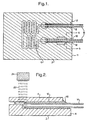
- First substrate 2 has a serpentine fluid flow channel 6 formed in the upper surface thereof extending from an inlet port 8 to an outlet port 10, both formed in an end surface 11 of the substrate.
- Fluid flow channel 6 may take various forms, depending upon the application, for example, large area chambers etc.
- Fluid flow channel 6 has a diameter, width or thickness less than 1000 micrometers, typically 100 micrometers, and may be of any suitable shape, for example triangular cross section.
- Fluid inlet port 8 and fluid outlet port 10 are both formed with apertures 12 formed in end surface 11 and having the form of bores, having a width, as shown more than twice that of channel 6.
- Apertures 12 receive capillary tubes 14 which may have a variety of sizes, for example 300 micrometers external diameter, 200 micrometers internal diameter, or 200 external, 150 internal, or 100 external 50 micrometers in diameter.
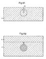
- the cross sectional shape of bores 12 may take a variety of forms as shown in Figure 6 namely (a) triangular, (b) truncated triangular, (c) semi circular, (d) rectangular, and (e) circular.
- bore 12 and fluid flow channels 6 are formed on the upper surface of base substrate 2 by building, by any suitable microengineering technique (defined by printing, photolithography, lamination, and modified by etching if required), layers 20 which define the side walls of the bore and fluid flow channels.
- the lower surface of the bore is defined by the upper surface of base substrate 2 and the upper surface of the bore is defined by the lower surface of substrate 4 which is subsequently bonded to layers 20.
- the upper surface of the layers 20 define, in part, the upper surface of said first substrate.
- the fluid coupling to inlet port 8 is formed differently from that to outlet port 10.
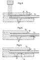
- capillary tube 14 is first inserted in to bore 12 close to a point where bore 12 merges with flow channel 6 at a shoulder 16.
- Capillary tube 14 may be formed of silica, but may be glass, polymer or even metal.
- a radiation curable material 18 is flowed into the open end of bore 12 and is such as to wick along bore 12 towards the end of tube 14.
- a beam of ultra violet radiation 22 is directed at the end of tube 14 from a light source 24 through transparent glass substrate 4 so that when the liquid reaches the beam it is hardened. Once a solid plug has been formed at the end of the tube 14, the light source may be moved along the length of the tube so as to cure and harden the remainder of liquid 18. Alternatively a second light source (not shown) is provided for general exposure of the liquid 18.
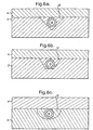
- a through aperture or via 30 is provided into which the radiation curable material is flowed. Otherwise the method is similar to that shown in Figure 2.
- the advantage of having a separate inlet via 30 for the radiation curable material is where the material is not sufficiently fluid to permit it to be flown from the end of fluid inlet port 8.
- FIG. 5 an alternative arrangement is shown for injecting a smaller amount of material, wherein a second via 50 is provided communicating with the bore and positioned adjacent to via 30.
- a second via 50 is provided communicating with the bore and positioned adjacent to via 30.
- an observer observes the ingress of sealant material into via 50, as shown by swelling 52, and at that point will appreciate that a sufficient amount of sealant material has been inserted and has reached the inner end of tube 14.
- the radiation curing material may most generally be a UV or light curing polymeric material.
- a variety of UV curing acrylic materials with a range of viscosities are available commercially (Norland UV Sealants, Norland Products Inc., New Brunswick, N.J. 08902, USA) and examples from that range (e.g. high viscosity Norland 91, low viscosity Norland 81) or similar materials may be selected for use in the methods described below where one or more of the substrate materials is transparent to the radiation.
- Feeding sealant into the aperture at a substrate edge is particularly convenient for low viscosity sealant which feeds into the guide channel by capillary action.
- low viscosity sealant it is necessary to provide a means of curing the sealant at the desired position in the guide channel by, for example, UV radiation so as to prevent the sealant running beyond the tube end and into the tube and the fluidic structure.
- curing may also be by radiation, but use of non-radiation curing sealant is also possible.
- a sufficiently viscous sealant especially a viscoelastic formulation
- flow within the guide channel is insignificant under capillary action but may be produced by pressure applied to the sealant at the aperture at a substrate edge, or by vacuum applied within the microengineered structure
- flow may be stopped by removing the pressure differential and the sealant cured or allowed to cure.
- An example is high viscosity two part epoxy which may be applied in e.g. Ciba Geigy Araldite 2005.
- the removal of the pressure differential may be in response to observation of the sealant front in the guide channel, or by observing sealant extruding from the channel, possibly automated with the aid of a vision system, or after a known time determined to produce the required amount of flow.
- the arrangements of Figures 4 and 5 would be particularly suitable.
- a molten sealant material may be used which solidifies at the desired position within the guide channel.
- Figure 7 and 8 show a modification of the method of Figure 4 wherein an insert rod member 70 is inserted into tube 14 so as to project beyond the end thereof into fluid flow channel 6.
- the insert 70 e.g. rod, fibre (possibly optical), wire, or narrower tube, is passed through tube 14 and into fluid channel 6.
- the sealant is allowed to flow beyond end of connection tube 14 and around insert 70 before curing.
- the insert is removed by pulling out (e.g. for tungsten wire, or optical fibre, possibly coated with release agent), or melting (e.g. for polypropylene or PMMA fibre or rod, or Indium wire), or dissolving (e.g. for Cu or Ni tubes).
- the substrates 2, 4 are of an opaque material.
- the radiation beam 90 is carried into the structure by an optical fibre 92 which is passed inside tube 14 which is transparent.
- the fibre could be passed through the flow channels 6.
- Radiation curing sealant 18 flows up the guide channel towards the end of the tube and is cured by the radiation, thus preventing sealant passing into tube and fluidic channels.
- the fibre optic is withdrawn slowly irradiating the rest of the sealant through the tube wall.
- this shows a method for precipitant sealing by flowing two liquids into the system which react to form a solid.
- concentrated viscous sodium silicate solution 100 is fed in though via 102, while a much less viscous solution 104 of for example a calcium or magnesium salt (e.g. CaCl 2 ) is fed in through tube 14.
- An insoluble silicate precipitate is formed at region 108 at the end of the tube.
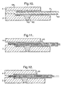
- both substrates 2, 4 are opaque and it is therefore necessary to use a viscous, preferably viscoelastic material 110 which can be injected into via 30 under pressure and which sets upon the release of pressure and/or the application of heat.
- a viscous, preferably viscoelastic material 110 which can be injected into via 30 under pressure and which sets upon the release of pressure and/or the application of heat.
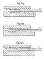
- FIGs 13a to 13 c show an eighth embodiment of the invention wherein a tube 14 has a preformed sleeve insert 130 formed around its inner end and of an external diameter less than that of bore 12. This allows free insertion of tube 14 within the bore as shown in Figure 13a. When fully positioned in the bore, heat is applied which causes the insert material to melt and form a seal between the tube 14 and the inner walls of the bore 12 as shown in Figure 13b.
- a sleeve insert material material 132 which expands after insertion by application of a chemical reactant to change the composition of the material, e.g. iron expanding to iron oxide.. Upon the removal of heat, the sealant material remains in the position shown in Figure 13c. It will be appreciated that in the embodiments of Figure 13 and 10, in particular, that where a plug is formed at the end of the tube, the remainder of the bore may subsequently be filled with a sealant material injected and hardened in accordance with any of the other embodiments, for example that in Figure2.
- sealants to radiation curable sealants may be employed.
- an anaerobic curing sealant which cures within the bore around the tube could be used, in which case sufficient control on the sealant flow rate and/or cure time is needed, and also, possibly a flush device with nitrogen or other oxygen free gas.
- the sealant material could be a viscous ceramic cement inserted by way of a via, as described with reference to Figure 3.
- Ceramic cements are Portland cement, plaster of Paris paste (hydrating gypsum CaSO 4 ), or phosphate cement (e.g., based on aluminium orthosposphate solution and MgO.
Landscapes
- Engineering & Computer Science (AREA)
- Mechanical Engineering (AREA)
- General Engineering & Computer Science (AREA)
- Physics & Mathematics (AREA)
- Electromagnetism (AREA)
- Chemical & Material Sciences (AREA)
- Toxicology (AREA)
- Health & Medical Sciences (AREA)
- Chemical Kinetics & Catalysis (AREA)
- Computer Hardware Design (AREA)
- Microelectronics & Electronic Packaging (AREA)
- Organic Chemistry (AREA)
- Theoretical Computer Science (AREA)
- Fluid Mechanics (AREA)
- General Chemical & Material Sciences (AREA)
- Physical Or Chemical Processes And Apparatus (AREA)
- Micromachines (AREA)
Abstract
Claims (17)
- Procédé pour la fabrication d'une connexion de fluide entre un tube à petit diamètre (14) et une structure micro-usinée pour servir de port d'écoulement de fluide à celui-ci, comprenant les étapes de : 1) fournir une structure micro-usinée présentant au moins un premier substrat plan (2, 4) avec des canaux (6) formés dans le substrat, le ou chaque substrat (2, 4) présentant des première et seconde surfaces latérales opposées, s'étendant sensiblement dans la même direction que le plan du ou de chaque substrat (2, 4) et des surfaces terminales (11) sensiblement normales au plan du ou de chaque substrat, une surface terminale (11) du au moins un substrat présentant une ouverture (12) dans celle-ci communiquant avec un canal d'écoulement de fluide (6) ; 2) fournir un tube capillaire ou autre tube à petit diamètre (14) et insérer une extrémité de celui-ci dans la libre ouverture (12) dans ladite surface terminale (11) ; et 3) provoquer l'écoulement dans l'ouverture (12) autour du tuyau (14) d'un matériau de scellement (18), qui est ensuite durci afin de sceller le tube (14) dans l'ouverture (12).
- Procédé selon la revendication 1, caractérisé en ce que la substance (18) comporte un matériau qui durci par radiation, et un faisceau de radiation (22) est dirigé à l'extrémité intérieure du tube dans l'ouverture (12), de manière que lorsque le matériau vulcanisable (18) est introduit dans l'ouverture (12), il durcit dès qu'il est atteint par le faisceau de radiation (22).
- Procédé selon la revendication 2, caractérisé en ce qu'une fois qu'un bouchon solide est formé à l'extrémité du tube (14), le faisceau (22) est déplacé le long du tube (14) pour durcir le reste du matériau (18) dans l'ouverture (12).
- Procédé selon la revendication 3, caractérisé en ce qu'un substrat (2, 4) est un matériau transparent et le faisceau de radiation (22) est dirigé au travers du substrat (2, 4) ou le tube (14) étant en un matériau transparent à la radiation, et la radiation est dirigée sur le matériau vulcanisable (18), via le tube (14).
- Procédé selon la revendication 1, caractérisé en ce que le substrat (18) est visqueux, de préférence viscoélastique ou pseudoplastique, et provoque son écoulement dans l'ouverture (12) ou sous pression, suite à l'enlèvement de la pression permettant à la substance (18) de durcir.
- Procédé selon la revendication 1, caractérisé en ce que la substance (18) est insérée dans le tube (14) sous forme fondue, à la suite du refroidissement de la substance (18) qui est ainsi susceptible de durcir.
- Procédé selon la revendication 1, caractérisé en ce que la substance (18) est un ciment inséré dans l'ouverture (12) sous une forme fluide, et subséquemment durci.
- Procédé selon la revendication 1, caractérisé en ce qu'une première substance est introduite dans ladite ouverture (102) et une seconde substance (104) est introduite au travers dudit tube (14), les deux substances (102, 104) se mélangeant et entrant en réaction dans l'extrémité intérieure (108) du tube afin de créer un scellement dans l'ouverture autour du tube (14).
- Procédé selon la revendication 1, caractérisé en ce qu'une substance est formée dans un insert cylindrique (130) à l'extrémité du tube (14) et d'une dimension externe permettant l'insertion libre du tube dans l'ouverture (12), et on fait fondre l'insert (130) lorsque le tube (14) est inséré dans l'ouverture (12) pour sceller le tube sur la surface intérieure de l'ouverture.
- Procédé selon l'une des revendications précédentes, caractérisé en ce qu'une substance (2, 4) présente un pasage (30) formé dans son travers pour communiquer avec ladite ouverture (12), afin de permettre l'écoulement de la substance (18) au travers de ladite ouverture (12).
- Procédé selon l'une des revendications précédentes, caractérisé en ce que la quantité de matériau (18) s'écoulant dans l'ouverture (12) est déterminée par l'observation physique du matériau dans l'ouverture.
- Procédé selon la revendication 11, caractérisé en ce qu'un autre passage (50) est prévu dans un substrat (2, 4) communiquant avec ladite ouverture (12) pour permettre l'observation du matériau de scellement (18) s'écoulant le long de l'ouverture et dans l'autre passage (50), afin de déterminer si la quantité de matériau suffisante s'est écoulée dans l'ouverture.
- Procédé selon l'une des revendications précédentes, caractérisé en ce qu'un membre d'insert (70) est inséré au travers du tube (14) dans le canal (6) d'écoulement de fluide afin de permettre à la substance (18) de s'écouler dans ladite ouverture (12), jusqu'à la connexion avec le canal (6) d'écoulement de fluide, sans bloquer le canal d'écoulement de fluide, la tige (70) étant enlevée du tube (14) après le durcissement de ladite substance (18).
- Procédé selon l'une des revendications précédentes, caractérisé en ce que l'ouverture (12) est formée par un canal de guides droits ou à faible courbure, ou conduits s'étendant depuis un canal d'écoulement de fluide vers la surface d'extrémité (11).
- Connexion de fluide entre le tube à petit diamètre (14) et une structure micro-usinée, ladite structure présentant au moins un premier substrat plan (2, 4) avec un ou plusieurs canal (6) d'écoulement de fluide, formé dans celui-ci, le ou chaque substrat (2, 4) présentant des première et des seconde surfaces latérales opposées s'étendant sensiblement dans la même direction que le plan du ou de chaque substrat (2, 4) et les surfaces d'extrémité (11) sensiblement normales au plan du ou de chaque substrat (2, 4), une surface terminale (11) du au moins un substrat présentant une ouverture, et incluant des moyens d'entrée de fluide comprenant un tube (14) à petit diamètre inséré dans l'ouverture (12), formée dans la surface terminale (11) du au moins un substrat (2, 4), ladite ouverture (12) communiquant avec un canal (6) d'écoulement de fluide, un matériau de scellement (18) étant prévu dans l'ouverture (12), ayant été durci in situ autour du tube dans l'ouverture, après l'insertion du tubage dans l'ouverture.
- Appareil comprenant une structure micro-usinée présentant une connexion de fluide selon la revendication 15.
- Procédé selon la revendication 16, caractérisé en ce que l'ouverture (12) est formée par un canal de guidage droit ou à faible courbure, ou un trou s'étendant depuis un canal d'écoulement de fluide vers ladite surface d'extrémité (11).
Applications Claiming Priority (3)
| Application Number | Priority Date | Filing Date | Title |
|---|---|---|---|
| GBGB9625491.7A GB9625491D0 (en) | 1996-12-07 | 1996-12-07 | Fluid connections |
| GB9625491 | 1996-12-07 | ||
| PCT/GB1997/003363 WO1998025065A1 (fr) | 1996-12-07 | 1997-12-04 | Raccord pour fluides |
Publications (2)
| Publication Number | Publication Date |
|---|---|
| EP0944794A1 EP0944794A1 (fr) | 1999-09-29 |
| EP0944794B1 true EP0944794B1 (fr) | 2002-08-28 |
Family
ID=10804126
Family Applications (1)
| Application Number | Title | Priority Date | Filing Date |
|---|---|---|---|
| EP97947789A Expired - Lifetime EP0944794B1 (fr) | 1996-12-07 | 1997-12-04 | Raccord pour fluides |
Country Status (10)
| Country | Link |
|---|---|
| US (1) | US6290791B1 (fr) |
| EP (1) | EP0944794B1 (fr) |
| JP (1) | JP2001505980A (fr) |
| KR (1) | KR20000057439A (fr) |
| CN (1) | CN1101909C (fr) |
| AU (1) | AU5403198A (fr) |
| CA (1) | CA2273861C (fr) |
| DE (1) | DE69715036T2 (fr) |
| GB (1) | GB9625491D0 (fr) |
| WO (1) | WO1998025065A1 (fr) |
Cited By (2)
| Publication number | Priority date | Publication date | Assignee | Title |
|---|---|---|---|---|
| DE102005000799A1 (de) * | 2005-01-05 | 2006-07-13 | Roche Diagnostics Gmbh | Fluidische Struktur und Verfahren zum Erzeugen einer fluidischen Struktur |
| DE112023000051B4 (de) * | 2022-04-22 | 2025-06-18 | Taisei Kogyo Co., Ltd. | Verfahren zur Herstellung einer Verbindungsstruktur |
Families Citing this family (62)
| Publication number | Priority date | Publication date | Assignee | Title |
|---|---|---|---|---|
| US7225019B2 (en) | 1996-04-30 | 2007-05-29 | Medtronic, Inc. | Method and system for nerve stimulation and cardiac sensing prior to and during a medical procedure |
| US7269457B2 (en) | 1996-04-30 | 2007-09-11 | Medtronic, Inc. | Method and system for vagal nerve stimulation with multi-site cardiac pacing |
| US8036741B2 (en) | 1996-04-30 | 2011-10-11 | Medtronic, Inc. | Method and system for nerve stimulation and cardiac sensing prior to and during a medical procedure |
| US6449507B1 (en) | 1996-04-30 | 2002-09-10 | Medtronic, Inc. | Method and system for nerve stimulation prior to and during a medical procedure |
| US6479523B1 (en) | 1997-08-26 | 2002-11-12 | Emory University | Pharmacologic drug combination in vagal-induced asystole |
| DE19746581A1 (de) | 1997-10-22 | 1999-04-29 | Merck Patent Gmbh | Mikromischer |
| GB9800220D0 (en) | 1998-01-06 | 1998-03-04 | Central Research Lab Ltd | Method of forming interconnections between channels and chambers |
| US6428053B1 (en) * | 1999-03-12 | 2002-08-06 | California Institute Of Technology | Micromachined fluidic coupler and method of making the same |
| US6322683B1 (en) * | 1999-04-14 | 2001-11-27 | Caliper Technologies Corp. | Alignment of multicomponent microfabricated structures |
| CA2376903A1 (fr) | 1999-06-25 | 2001-01-04 | Emory University | Dispositifs et methodes de stimulation du nerf vague |
| GB0011428D0 (en) * | 2000-05-12 | 2000-06-28 | Central Research Lab Ltd | Method of forming a fluid tight seal |
| GB0011575D0 (en) * | 2000-05-12 | 2000-07-05 | Central Research Lab Ltd | An adaptor for receiving a fluidic device |
| US6487446B1 (en) | 2000-09-26 | 2002-11-26 | Medtronic, Inc. | Method and system for spinal cord stimulation prior to and during a medical procedure |
| FR2813073A1 (fr) * | 2000-12-19 | 2002-02-22 | Commissariat Energie Atomique | Dispositif de positionnement et de guidage pour la connexion etanche de capillaires a un micro-composant |
| WO2003031044A2 (fr) * | 2001-10-05 | 2003-04-17 | Vanderbilt University | Pointes d'impression a tubes capillaires pour impression de microreseaux |
| JP3933190B2 (ja) * | 2002-02-25 | 2007-06-20 | 日立化成工業株式会社 | マイクロ流体システム用支持ユニット |
| JP3933058B2 (ja) | 2002-02-25 | 2007-06-20 | 日立化成工業株式会社 | マイクロ流体システム用支持ユニット及びその製造方法 |
| US6926989B2 (en) * | 2002-06-05 | 2005-08-09 | Motorola, Inc. | Interconnect apparatus for fuel cells |
| US20040061257A1 (en) * | 2002-09-27 | 2004-04-01 | The Regents Of The University Of Michigan | Packaging technique for elastomeric microfluidic chips and microfluidic device prepared thereby |
| US7541007B2 (en) * | 2002-12-20 | 2009-06-02 | Lehigh University | Microreactor and method of use to produce hydrogen by methanol reforming |
| DE10308050A1 (de) * | 2003-02-26 | 2004-09-09 | Abb Research Ltd. | Verfahren zum Verbinden von Röhrchen mit Kanälen von Trägerelementen |
| US7011793B2 (en) * | 2003-05-15 | 2006-03-14 | Kionix, Inc. | Reconfigurable modular microfluidic system and method of fabrication |
| EP1628706A1 (fr) * | 2003-06-03 | 2006-03-01 | Mixpac Systems AG | Dispositif pour raccorder une tubule a un melangeur |
| JP4953816B2 (ja) * | 2003-08-06 | 2012-06-13 | ウオーターズ・テクノロジーズ・コーポレイシヨン | 流体端末装置 |
| DE10345817A1 (de) * | 2003-09-30 | 2005-05-25 | Boehringer Ingelheim Microparts Gmbh | Verfahren und Vorrichtung zum Koppeln von Hohlfasern an ein mikrofluidisches Netzwerk |
| WO2005061878A2 (fr) * | 2003-12-19 | 2005-07-07 | Siemens Vdo Automotive Corporation | Injecteurs de carburant a corps polymere, et procede de fabrication correspondant |
| US7351380B2 (en) * | 2004-01-08 | 2008-04-01 | Sandia Corporation | Microfluidic structures and methods for integrating a functional component into a microfluidic device |
| KR100927288B1 (ko) * | 2004-02-18 | 2009-11-18 | 히다치 가세고교 가부시끼가이샤 | 마이크로 유체시스템용 지지유닛 |
| JP5148267B2 (ja) * | 2004-04-02 | 2013-02-20 | エービー サイエックス エルエルシー | 微小溶液の接続 |
| WO2005102509A1 (fr) * | 2004-04-27 | 2005-11-03 | Agilent Technologies, Inc. | Raccord microfluidique |
| WO2006050755A1 (fr) * | 2004-11-11 | 2006-05-18 | Agilent Technologies, Inc. | Collage de deux pieces par arret d'un adhesif liquide |
| US8480970B2 (en) | 2004-11-30 | 2013-07-09 | Hitachi Chemical Co., Ltd. | Analytical pretreatment device |
| KR20070085991A (ko) * | 2004-12-09 | 2007-08-27 | 히다치 가세고교 가부시끼가이샤 | 마이크로 유체 시스템용 지지유닛 및 그 제조방법 |
| US20060249441A1 (en) * | 2005-05-04 | 2006-11-09 | Baur Jeffery W | Nanofluidic connector for hollow microfiber and method for manufacture thereof |
| SE0501053L (sv) * | 2005-05-10 | 2006-05-16 | Kvaerner Power Ab | Insatstub samt ett system av insatstuber |
| WO2007021815A2 (fr) * | 2005-08-11 | 2007-02-22 | Eksigent Technologies, Llc | Appareils, systemes et procedes a puce microfluidique possedant des interconnexions fluidiques et a fibres optiques |
| US8152477B2 (en) | 2005-11-23 | 2012-04-10 | Eksigent Technologies, Llc | Electrokinetic pump designs and drug delivery systems |
| JP2007147456A (ja) | 2005-11-28 | 2007-06-14 | Seiko Epson Corp | マイクロ流体システム、試料分析装置、及び標的物質の検出または測定方法 |
| US7867592B2 (en) | 2007-01-30 | 2011-01-11 | Eksigent Technologies, Inc. | Methods, compositions and devices, including electroosmotic pumps, comprising coated porous surfaces |
| US20100218834A1 (en) * | 2007-01-30 | 2010-09-02 | Diramo A/S | Micro fluid device with a multi lumen hose |
| WO2009076134A1 (fr) | 2007-12-11 | 2009-06-18 | Eksigent Technologies, Llc | Pompe électrocinétique présentant un volume de course fixe |
| US20100199750A1 (en) | 2009-02-06 | 2010-08-12 | Arnold Don W | Microfludic Analysis System and Method |
| US8639327B2 (en) | 2010-04-29 | 2014-01-28 | Medtronic, Inc. | Nerve signal differentiation in cardiac therapy |
| US8406868B2 (en) | 2010-04-29 | 2013-03-26 | Medtronic, Inc. | Therapy using perturbation and effect of physiological systems |
| US8620425B2 (en) | 2010-04-29 | 2013-12-31 | Medtronic, Inc. | Nerve signal differentiation in cardiac therapy |
| GB2486679B (en) * | 2010-12-22 | 2017-10-04 | Agilent Technologies Inc | Dual-material approach for high pressure bioinert flow path components |
| US8781583B2 (en) | 2011-01-19 | 2014-07-15 | Medtronic, Inc. | Vagal stimulation |
| US8725259B2 (en) | 2011-01-19 | 2014-05-13 | Medtronic, Inc. | Vagal stimulation |
| US8706223B2 (en) | 2011-01-19 | 2014-04-22 | Medtronic, Inc. | Preventative vagal stimulation |
| US8781582B2 (en) | 2011-01-19 | 2014-07-15 | Medtronic, Inc. | Vagal stimulation |
| US8718763B2 (en) | 2011-01-19 | 2014-05-06 | Medtronic, Inc. | Vagal stimulation |
| WO2012116753A1 (fr) | 2011-03-03 | 2012-09-07 | Agilent Technologies, Inc. | Capillaire revêtu doté d'un revêtement refondu pour l'étanchéification du côté avant |
| US9791080B2 (en) | 2012-03-12 | 2017-10-17 | Idex Health & Science Llc | Microfluidic interconnect |
| JP2014028343A (ja) * | 2012-07-31 | 2014-02-13 | National Institute Of Advanced Industrial & Technology | マイクロ反応器における外部配管の接合方法並びに該方法により接合された接合構造を有するマイクロ反応器、そのバンドル並びにモジュール構造 |
| EP2719460B1 (fr) * | 2012-10-12 | 2016-12-14 | Sony DADC Austria AG | Dispositifs microfluidiques |
| WO2014132103A1 (fr) * | 2013-02-28 | 2014-09-04 | Agilent Technologies, Inc. | Connexion fluide intégrée de structures planes pour dispositifs de séparation d'échantillons |
| JP2014234411A (ja) * | 2013-05-31 | 2014-12-15 | Jsr株式会社 | マイクロ流路形成用嫌気硬化性樹脂組成物およびマイクロ流路 |
| JP2014210865A (ja) * | 2013-04-19 | 2014-11-13 | Jsr株式会社 | マイクロ流路形成用放射線硬化性樹脂組成物およびマイクロ流路 |
| US20160096353A1 (en) * | 2014-10-07 | 2016-04-07 | The Boeing Company | Structure including a light-curable adhesive and associated method for assembling and curing same |
| WO2017181258A1 (fr) * | 2016-04-21 | 2017-10-26 | Duane Hewitt | Système de flux continu |
| CN111721424A (zh) * | 2019-03-20 | 2020-09-29 | 北京振兴计量测试研究所 | 一种真空低温环境下红外辐射计用温度传感器安装方法 |
| CN113797986B (zh) * | 2021-10-11 | 2023-05-26 | 苏州美翎生物医学科技有限公司 | 一种可微调毛细管同轴排列的微流控芯片 |
Family Cites Families (11)
| Publication number | Priority date | Publication date | Assignee | Title |
|---|---|---|---|---|
| US4390575A (en) * | 1981-12-02 | 1983-06-28 | Baxter Travenol Laboratories, Inc. | Multichanneled diffusion device |
| GB8727902D0 (en) * | 1987-11-28 | 1987-12-31 | Emi Plc Thorn | Method of forming a solid article |
| US4969938A (en) * | 1990-01-03 | 1990-11-13 | The Perkin-Elmer Corporation | Fluid connector for microdevices |
| SE470347B (sv) * | 1990-05-10 | 1994-01-31 | Pharmacia Lkb Biotech | Mikrostruktur för vätskeflödessystem och förfarande för tillverkning av ett sådant system |
| US5601785A (en) * | 1991-12-23 | 1997-02-11 | Microsensor Technology, Inc. | Connector for detachable column cartridge for gas chromatograph |
| US5611846A (en) * | 1994-01-14 | 1997-03-18 | Board Of Supervisors Of Louisiana State University And Agricultural And Mechanical College | Portable gas chromatograph |
| DE9413553U1 (de) | 1994-08-23 | 1994-10-13 | Hewlett-Packard GmbH, 71034 Böblingen | Verbindungskapillare |
| ATE235292T1 (de) | 1994-10-22 | 2003-04-15 | Central Research Lab Ltd | Verfahren und vorichtung fur diffusionsaustausch zwischen nicht mischbare flüssigkeiten |
| EP0789238A1 (fr) * | 1996-02-07 | 1997-08-13 | Chrompack International B.V. | Dispositif d'interface exchangeable entre des composants de système chromatographique et des chromatographes miniaturisés en phase gazeuse |
| US5779868A (en) * | 1996-06-28 | 1998-07-14 | Caliper Technologies Corporation | Electropipettor and compensation means for electrophoretic bias |
| US6149787A (en) * | 1998-10-14 | 2000-11-21 | Caliper Technologies Corp. | External material accession systems and methods |
-
1996
- 1996-12-07 GB GBGB9625491.7A patent/GB9625491D0/en active Pending
-
1997
- 1997-12-04 AU AU54031/98A patent/AU5403198A/en not_active Abandoned
- 1997-12-04 CN CN97181282A patent/CN1101909C/zh not_active Expired - Fee Related
- 1997-12-04 EP EP97947789A patent/EP0944794B1/fr not_active Expired - Lifetime
- 1997-12-04 DE DE69715036T patent/DE69715036T2/de not_active Expired - Fee Related
- 1997-12-04 WO PCT/GB1997/003363 patent/WO1998025065A1/fr not_active Ceased
- 1997-12-04 JP JP52536498A patent/JP2001505980A/ja active Pending
- 1997-12-04 US US09/319,445 patent/US6290791B1/en not_active Expired - Fee Related
- 1997-12-04 CA CA002273861A patent/CA2273861C/fr not_active Expired - Fee Related
- 1997-12-04 KR KR1019990705054A patent/KR20000057439A/ko not_active Withdrawn
Cited By (2)
| Publication number | Priority date | Publication date | Assignee | Title |
|---|---|---|---|---|
| DE102005000799A1 (de) * | 2005-01-05 | 2006-07-13 | Roche Diagnostics Gmbh | Fluidische Struktur und Verfahren zum Erzeugen einer fluidischen Struktur |
| DE112023000051B4 (de) * | 2022-04-22 | 2025-06-18 | Taisei Kogyo Co., Ltd. | Verfahren zur Herstellung einer Verbindungsstruktur |
Also Published As
| Publication number | Publication date |
|---|---|
| DE69715036D1 (de) | 2002-10-02 |
| WO1998025065A1 (fr) | 1998-06-11 |
| CA2273861C (fr) | 2004-06-15 |
| CN1101909C (zh) | 2003-02-19 |
| CN1244239A (zh) | 2000-02-09 |
| EP0944794A1 (fr) | 1999-09-29 |
| KR20000057439A (ko) | 2000-09-15 |
| CA2273861A1 (fr) | 1998-06-11 |
| JP2001505980A (ja) | 2001-05-08 |
| US6290791B1 (en) | 2001-09-18 |
| DE69715036T2 (de) | 2003-04-30 |
| GB9625491D0 (en) | 1997-01-22 |
| AU5403198A (en) | 1998-06-29 |
Similar Documents
| Publication | Publication Date | Title |
|---|---|---|
| EP0944794B1 (fr) | Raccord pour fluides | |
| JP4851698B2 (ja) | マイクロ流体ネットワークにおける中空繊維を結合する方法およびマイクロ流体システム | |
| KR101533854B1 (ko) | 유체 처리용 압출 본체 장치 및 방법 | |
| US5890745A (en) | Micromachined fluidic coupler | |
| EP1855038B1 (fr) | Vanne à transition de phase et procédé de fabrication correspondant | |
| US20070012891A1 (en) | Prototyping methods and devices for microfluidic components | |
| US6626468B2 (en) | Pipe joint, its manufacturing method, and fluid device using the same | |
| US7933012B2 (en) | Microfluidic chip apparatuses, systems and methods having fluidic and fiber optic interconnections | |
| US10160071B2 (en) | Co-extruded microchannel heat pipes | |
| CN106232326A (zh) | 用于形成和用于拆卸气密性密封腔室的方法 | |
| KR20080090410A (ko) | 정밀한 라인 접합 및/또는 밀봉 시스템과 그 방법 | |
| US20090041624A1 (en) | Fluidic structure and method for production of a fluid structure | |
| CN101435808B (zh) | 一种制备三维微管道或腔体的方法与应用 | |
| US8518481B2 (en) | Interconnect for MEMS device including a viscoelastic septum | |
| Hartmann et al. | A low-cost, manufacturable method for fabricating capillary and optical fiber interconnects for microfluidic devices | |
| CN101657260B (zh) | 具有多腔软管的微流体装置 | |
| US6926989B2 (en) | Interconnect apparatus for fuel cells | |
| US8283109B2 (en) | Method for obtaining microfluidic polymer structures | |
| DE102012201714B4 (de) | Verfahren zur herstellung von mikrofluidsystemen | |
| JP2006183818A (ja) | マイクロバルブ装置およびその制御方法 | |
| TWI403359B (zh) | 流體處理過程擠製物體為主裝置及方法 | |
| CN115770630A (zh) | 一种新型三维微混合器的制造工艺方法 | |
| Thompson | Reversible concentric ring microfluidic interconnects |
Legal Events
| Date | Code | Title | Description |
|---|---|---|---|
| PUAI | Public reference made under article 153(3) epc to a published international application that has entered the european phase |
Free format text: ORIGINAL CODE: 0009012 |
|
| 17P | Request for examination filed |
Effective date: 19990707 |
|
| AK | Designated contracting states |
Kind code of ref document: A1 Designated state(s): CH DE ES FR GB IT LI NL |
|
| GRAG | Despatch of communication of intention to grant |
Free format text: ORIGINAL CODE: EPIDOS AGRA |
|
| 17Q | First examination report despatched |
Effective date: 20011106 |
|
| GRAG | Despatch of communication of intention to grant |
Free format text: ORIGINAL CODE: EPIDOS AGRA |
|
| GRAH | Despatch of communication of intention to grant a patent |
Free format text: ORIGINAL CODE: EPIDOS IGRA |
|
| GRAH | Despatch of communication of intention to grant a patent |
Free format text: ORIGINAL CODE: EPIDOS IGRA |
|
| GRAA | (expected) grant |
Free format text: ORIGINAL CODE: 0009210 |
|
| AK | Designated contracting states |
Kind code of ref document: B1 Designated state(s): CH DE ES FR GB IT LI NL |
|
| PG25 | Lapsed in a contracting state [announced via postgrant information from national office to epo] |
Ref country code: LI Free format text: LAPSE BECAUSE OF FAILURE TO SUBMIT A TRANSLATION OF THE DESCRIPTION OR TO PAY THE FEE WITHIN THE PRESCRIBED TIME-LIMIT Effective date: 20020828 Ref country code: CH Free format text: LAPSE BECAUSE OF FAILURE TO SUBMIT A TRANSLATION OF THE DESCRIPTION OR TO PAY THE FEE WITHIN THE PRESCRIBED TIME-LIMIT Effective date: 20020828 |
|
| REG | Reference to a national code |
Ref country code: GB Ref legal event code: FG4D |
|
| REG | Reference to a national code |
Ref country code: CH Ref legal event code: EP |
|
| REF | Corresponds to: |
Ref document number: 69715036 Country of ref document: DE Date of ref document: 20021002 |
|
| PG25 | Lapsed in a contracting state [announced via postgrant information from national office to epo] |
Ref country code: ES Free format text: LAPSE BECAUSE OF FAILURE TO SUBMIT A TRANSLATION OF THE DESCRIPTION OR TO PAY THE FEE WITHIN THE PRESCRIBED TIME-LIMIT Effective date: 20030228 |
|
| REG | Reference to a national code |
Ref country code: CH Ref legal event code: PL |
|
| ET | Fr: translation filed | ||
| PLBE | No opposition filed within time limit |
Free format text: ORIGINAL CODE: 0009261 |
|
| STAA | Information on the status of an ep patent application or granted ep patent |
Free format text: STATUS: NO OPPOSITION FILED WITHIN TIME LIMIT |
|
| 26N | No opposition filed |
Effective date: 20030530 |
|
| REG | Reference to a national code |
Ref country code: GB Ref legal event code: 732E |
|
| REG | Reference to a national code |
Ref country code: GB Ref legal event code: 732E |
|
| PGFP | Annual fee paid to national office [announced via postgrant information from national office to epo] |
Ref country code: NL Payment date: 20080325 Year of fee payment: 11 |
|
| REG | Reference to a national code |
Ref country code: FR Ref legal event code: TP |
|
| NLS | Nl: assignments of ep-patents |
Owner name: BRITISH NUCLEAR FUELS PLC Effective date: 20080522 |
|
| PGFP | Annual fee paid to national office [announced via postgrant information from national office to epo] |
Ref country code: IT Payment date: 20080331 Year of fee payment: 11 |
|
| NLS | Nl: assignments of ep-patents |
Owner name: NUCLEAR DECOMMISSIONING AUTHORITY Effective date: 20090115 |
|
| PGFP | Annual fee paid to national office [announced via postgrant information from national office to epo] |
Ref country code: DE Payment date: 20090212 Year of fee payment: 12 |
|
| PGFP | Annual fee paid to national office [announced via postgrant information from national office to epo] |
Ref country code: GB Payment date: 20090130 Year of fee payment: 12 |
|
| NLV4 | Nl: lapsed or anulled due to non-payment of the annual fee |
Effective date: 20090701 |
|
| PGFP | Annual fee paid to national office [announced via postgrant information from national office to epo] |
Ref country code: FR Payment date: 20090213 Year of fee payment: 12 |
|
| PG25 | Lapsed in a contracting state [announced via postgrant information from national office to epo] |
Ref country code: NL Free format text: LAPSE BECAUSE OF NON-PAYMENT OF DUE FEES Effective date: 20090701 |
|
| GBPC | Gb: european patent ceased through non-payment of renewal fee |
Effective date: 20091204 |
|
| REG | Reference to a national code |
Ref country code: FR Ref legal event code: ST Effective date: 20100831 |
|
| PG25 | Lapsed in a contracting state [announced via postgrant information from national office to epo] |
Ref country code: FR Free format text: LAPSE BECAUSE OF NON-PAYMENT OF DUE FEES Effective date: 20091231 |
|
| PG25 | Lapsed in a contracting state [announced via postgrant information from national office to epo] |
Ref country code: DE Free format text: LAPSE BECAUSE OF NON-PAYMENT OF DUE FEES Effective date: 20100701 |
|
| PG25 | Lapsed in a contracting state [announced via postgrant information from national office to epo] |
Ref country code: GB Free format text: LAPSE BECAUSE OF NON-PAYMENT OF DUE FEES Effective date: 20091204 |
|
| PG25 | Lapsed in a contracting state [announced via postgrant information from national office to epo] |
Ref country code: IT Free format text: LAPSE BECAUSE OF NON-PAYMENT OF DUE FEES Effective date: 20081204 |