EP0944889B1 - Procede pour informer un central sur le chemin parcouru par un vehicule dans un reseau routier, terminal, central - Google Patents
Procede pour informer un central sur le chemin parcouru par un vehicule dans un reseau routier, terminal, central Download PDFInfo
- Publication number
- EP0944889B1 EP0944889B1 EP97953605A EP97953605A EP0944889B1 EP 0944889 B1 EP0944889 B1 EP 0944889B1 EP 97953605 A EP97953605 A EP 97953605A EP 97953605 A EP97953605 A EP 97953605A EP 0944889 B1 EP0944889 B1 EP 0944889B1
- Authority
- EP
- European Patent Office
- Prior art keywords
- terminal
- vehicle
- data
- location
- process according
- Prior art date
- Legal status (The legal status is an assumption and is not a legal conclusion. Google has not performed a legal analysis and makes no representation as to the accuracy of the status listed.)
- Expired - Lifetime
Links
Images




Classifications
-
- G—PHYSICS
- G08—SIGNALLING
- G08G—TRAFFIC CONTROL SYSTEMS
- G08G1/00—Traffic control systems for road vehicles
- G08G1/20—Monitoring the location of vehicles belonging to a group, e.g. fleet of vehicles, countable or determined number of vehicles
-
- G—PHYSICS
- G08—SIGNALLING
- G08G—TRAFFIC CONTROL SYSTEMS
- G08G1/00—Traffic control systems for road vehicles
- G08G1/01—Detecting movement of traffic to be counted or controlled
Definitions
- the invention relates to a method for informing a center of the a vehicle covered in a traffic network, a terminal and a Headquarters.
- the detection of the path of a vehicle is part of the wrong-way detection interactive navigation and to gain geographic referenceable Suitable for traffic information; the latter traffic information from one Central for assigning traffic data, such as vehicle speeds, Travel times etc. to places on the way of the vehicle, i.e. to places in one digital map of the transport network can be used at the headquarters, due to of traffic data from several vehicles in the central traffic status reports, Traffic forecasts and optimal navigation aids for transmission one vehicle each can be generated.
- the path of the vehicle through a Location data relating to the traffic network can be obtained from, in particular, via mobile radio Terminal in the vehicle can be transmitted to a control center.
- the available here standing transmission capacity of the communication channel is limited; in particular, the amount of information transmitted increases Telecommunications costs.
- EP-A-0 731 400 discloses a method for informing a center about a path covered by a vehicle in a transport network, wherein on the vehicle side with a GPS system the vehicle location is repeatedly recorded and on a central support point to be transferred if existing ones apply Criteria regarding the maximum vertical distance of a detected location a vector train.
- Criteria regarding the maximum vertical distance of a detected location a vector train are more common in cornering Exceeding a predeterminable maximum vertical distance to one Vector train set support points more often than during a straight line.
- the object of the invention is to inform a central office about the information provided by one Vehicle covered in a traffic network with as little as possible Amount of information transmitted that shows the path of the vehicle in the vehicle Traffic network in the most efficient and precisely reconstructable way represent.
- the task is carried out by the subjects of the independent Claims resolved.
- the invention optimizes the amount of information transmitted to the path of the Vehicle; nevertheless, the path can be easily reconstructed, since at relevant locations along points of the way of the vehicle are defined, to which information be transmitted.
- the criteria according to which is determined, at which locations along the route of the vehicle is defined by a traffic network, are specified or can be specified in the terminal.
- the criteria can be radio, in particular mobile radio, etc., can be changed by a center for a terminal.
- Support point information is transmitted to the defined support points; this can in particular include the last recorded location of the terminal. Further they can include the current direction of travel of the end device.
- the location is from the terminal with a position detection device, especially with GPS.
- the location of the terminal is thus from independent of a digital card etc.
- From at least two successive locations along the way recorded location data can change the direction of a vehicle between them directional data representing at least two locations are determined.
- directional data representing at least two locations are determined.
- the direction of travel of the terminal at or between at least Direction data representing two locations can be sent from the terminal to the control center be transmitted.
- direction data can also be used as an angle towards a given direction, for example towards one Cardinal points, to be determined, whereby it makes sense to point the cardinal points in the Terminal e.g. through a compass and / or position tracking with a determine digital map.
- From the directional data or from an angle Representing angle data for at least two locations can change the angle can be detected within a predetermined unit of time. With that a Change in direction of the vehicle can be detected. With a suitable choice of Unit of time will be short-term changes in direction, such as when overtaking, etc. filtered out and only relevant changes of direction, such as the Turning into a street, with larger curves of a street, etc., which is recorded for a control center are important and in the terminal for the definition of a support point are usable.
- a memory is provided in the terminal for storing data; Using of a ring buffer is a storage of the last one with a small storage capacity and thus the particularly relevant data is possible.
- the support points can be defined in different ways in the terminal.
- a support point can be defined when the vehicle has been the last base more than a predetermined or predeterminable Minimum distance limit has covered and the vehicle angle within a predefined or predefinable one (especially from a central office via Cellular unit predeterminable) unit of time by more than a predetermined or (from a control center) predeterminable angle limit changes.
- a predefined or predefinable one especially from a central office via Cellular unit predeterminable unit of time by more than a predetermined or (from a control center) predeterminable angle limit changes.
- At least two angles (or directions) of the vehicle at at least two Locations in the terminal and the resulting difference is compared with a Angle limit compared. If the angle is above the angle limit, a support point can be defined.
- a base can also be defined if the vehicle is more than a predetermined or predeterminable Maximum distance limit moved.
- the terminal appropriately detects the Movement of the vehicle based on a vehicle distance meter (Odometer) and / or a location in at least two locations and a difference calculation of these two locations. This becomes a support point definition defined at least in predefinable limit intervals along the way. Thus, even if the direction of travel of the vehicle does not change, at least to these Intervals support point information from the terminal to the control center.
- Useful values are 45 ° for the angle limit and for the distance limit 1000 m.
- a support point definition of one is more current due to the extent Angular changes depending on the stability state.
- One can Stability of the vehicle can be defined in such a way that changes in angle the vehicle by more than an angular stability limit (for example 10 °), which is suitably smaller than the angle limit (45 °), the state is unstable and that the state is stable below the angular stability limit.
- an angular stability limit for example 10 °
- the angle limit 45 °
- a support point definition can be omitted; she can but still take place when the unstable state along a Distance stability value (for example 150 m), which is suitably smaller than is the maximum distance limit. Doing so during an unstable Condition according to a distance stability limit (for example 150 m) Base despite persistent instability (i.e.
- the criteria for defining a base in the terminal are useful changeable and changeable from a central, in particular via mobile radio.
- a central in particular via mobile radio.
- there are in particular the angle limit value and / or the maximum distance limit value and / or the minimum distance limit value and / or the angular stability value and / or the Distance stability limit can be changed. It can also be changeable which data a terminal at a base or to a base to the head office has to be transferred.
- the transmission of data from a terminal to a control center expediently comprises in a transmitted data record, data on several support points, especially to the last support points that drive through the terminal in the vehicle Has.
- support points can be sent from the terminal to the control center other data such as vehicle speed, Vehicle speed variants etc. are transmitted.
- the method according to the invention is in a terminal or in a control center in realizable in a program.
- FIG. 1 shows a vehicle 101 with a terminal device 102, which is different from a Starting position 103 up to its current position by a (here excerpt shown) traffic network 104, 105, 106 moves. That currently at its current Vehicle 101, 102 located in position 112 should control center 107 via its previous route 103, 112 with the smallest possible amount of data transmitted in this way inform that the route in headquarters 107 can be reconstructed as well as possible and for example, can be assigned to a digital map in the central office 107.
- a traffic network 104, 105, 106 moves. That currently at its current Vehicle 101, 102 located in position 112 should control center 107 via its previous route 103, 112 with the smallest possible amount of data transmitted in this way inform that the route in headquarters 107 can be reconstructed as well as possible and for example, can be assigned to a digital map in the central office 107.
- a Location detection device repeats the respective location of the terminal representing representative location data. This can be due to a GPS system, for example done in the terminal.
- Location data representing a detected location can for example, the longitude and latitude of the location in the terminal and in the central predetermined rounding include.
- a location survey can for example, continuously in one-second intervals, etc.
- support points 108, 109, 110, 111, 112 are defined in the terminal lie on the path covered and to which support points 108 to 112 in each case Base information, in particular the location of each base representing location data, from the terminal device 102 to the control center 107 via mobile radio etc. be transferred 13.
- Base information in particular the location of each base representing location data, from the terminal device 102 to the control center 107 via mobile radio etc. be transferred 13.
- the criteria according to which support points are defined are Specified in the terminal and can be changed here from a central station via mobile radio etc. 14.
- the criteria can include, in particular, the type of direction changes and / or the length of the since a last base or since a certain state of the Concern the distance traveled.
- the location of the terminal is recorded with GPS, etc.; a path traveled between two locations, especially since the last base, can e.g. through difference formation the location coordinates can be determined in the terminal.
- the determination of the direction 15 to 19 in which a vehicle is traveling can be based on of location data at least two locations and / or based on one Direction detection device, such as a compass 20, take place in the terminal.
- the direction of travel of a vehicle can be an angle, for example against a compass direction, for example towards north.
- the directions 15 to 19 have, for example, the angles with the numbers 21 to 25 to the north.
- an angle limit (angle-deviation) is exceeded in Fig. 5) from here 45 ° within a predetermined distance or unit of time a support point is defined in any case. This can be a turn in particular of a vehicle can be detected.
- the angle limit is the change in angle of the vehicle between the current position and any other Position within a distance with a predefinable length or within a Time interval.
- the time interval can e.g. be the interval in which the terminal Receives GPS data.
- short-term angle fluctuations of the vehicle can be defined one of these implicit stability criteria or filtered out of stability criteria become. This can be used, for example, to drive around a parked vehicle or a direction of travel fluctuation e.g. hidden due to drunk driving become.
- the definition of a support point within a curve can also be avoided become. This means that changes in angle below the angle limit (here 45 °) and detected above an angle stability limit of, for example, 10 ° become and in this case an unstable state, which is a relatively quick represents the pivoting direction. During an unstable In general, the definition of a support point can be omitted.
- an unstable state of the vehicle can be defined if the Difference in the direction of travel of a vehicle within a distance limit (for example, 30 m) a predetermined number at least once or more of painting is above an angular stability value (10 °).
- a distance limit for example, 30 m
- a predetermined number at least once or more of painting is above an angular stability value (10 °).
- an angular stability value 10 °.
- Support points are defined (except when the distance limit or the Angle limit is exceeded).
- it can also indicate an unstable condition of a vehicle according to a distance stability limit value (stable max wait in FIG. 5) a support point is nevertheless defined.
- All of the above values can be predefined in the terminal or from a central station be changeable for a terminal via mobile radio etc.
- FIG. 3 explains this stability definition and thus criteria as a state diagram, based on which support points are defined.
- state 30 unstable and waiting
- state 31 stable
- state 32 end
- the state 32 (end) is, for example, by pressing a trigger button on the terminal triggered. This can be the case, for example, at the end of a journey Removing an ignition key, etc., happen.
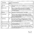
- FIG. 5 shows the implementation of a program, in particular according to the Transition diagram in Figure 3 and the table in Figure 4 suitable for this Parameter definitions. Based on these parameters, criteria for the excitation the definition of a base and additional conditions for the definition of a stimulated support point can be defined.
- the definition (pearl throw) of a base (Pearl) is excited according to lines 1 and 2 in Figure 5 if the vehicle since last support point more than a maximum distance limit (dist-max) from here 1000 m or if the vehicle is currently in a Direction of travel.
- Angle-Abwei angle limit
- distal-min minimum distance limit
- an angle stability limit value (stable angle) of here 10 ° towards you at a certain time or a certain way previous place is available; this can be avoided that a support point on Location of a short-term change in angle or during an angle change. If the condition of the vehicle due to the current exceeding of the Angle limit value (stable angle) of 10 ° here is one even after excitation Support point no support point defined; possibly an assumption of instability a vehicle only if there is another criterion; so can for example an assumption of instability when a Angular stability limit (stable angle) only take place if the Angular stability limit (stabeil angle) at least along one Instability distance limit value (stable path) from here 30 m is exceeded For example, short-term angle fluctuations when driving around a parked Filter out vehicle when changing lanes or when drunk.
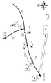
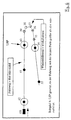
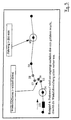
- Figures 6 to 9 illustrate examples of the conditions for stimulating the Definition of a support point and for additional conditions for the definition of a support point.
- a location detection device here GPS
- the route of the vehicle during a stable state, the path of the vehicle is in an unstable state is shown in dashed lines and lighter.
- the place where a support point was defined (or at which a "pearl" was thrown) was shown as a circle.
- the support points are therefore called pearls referred to, because the path of a vehicle marked with pearls is optically here corresponds to a pearl necklace.
- the vehicle 101 moved coming from the top left to the right in FIG. 6, then around the curve and then to the bottom left in Figure 6. It was on the Points 42 to 33 from the location detection device 20 in the vehicle to a terminal one vehicle position reported in the vehicle; the reason why the points in the curve area on the right in FIG. 6, one can see that the vehicle is moving slowly here. Now, in order to get the best possible Reconstruction of the route in a control center to enable it to be determined which support points along the route are location information transmitted. No location information is transmitted in the area of a curve because this have too little information.
- the vehicle accelerates here, which is why the points to which the location detection system in the vehicle delivers data spatially apart.
- the route (between 34 and 33) is below the Angle limit value (angle-different) lying angle change (here no angle change) stable, so that after driving through a maximum distance limit (dist-max) crossing route at the next point, to which location data a support point can be defined.
- the vehicle moves from the top left to the right around the curve and from right to bottom left over the points (with available location data from the Location data acquisition device) 43 to 52.
- point 44 is the maximum distance limit (dist-max) exceeded since the last defined support point and the State (due to below the angle stability limit value (stable-angle) lying change in angle (here no change in angle)) stable, so that at point 44 a base is defined.
- the next crossing of the The maximum distance limit (dist-max) of the route takes place in the area of curve 46 to 50.
- no last stable point is defined at point 45 because of the distance to the last support point 44 is less than dist-min stable.
- a last stable point was defined at point 53 in FIG. However, it will not Reference point definition stimulated, since neither an angle change over an angle limit (angle-off) there was still a distance above a maximum distance limit (dist-max) was covered.
- FIG 9 the vehicle moves from left to right.
- a support point was defined at point 54. This was followed by changes in angle at points 55 to 58 above the angle limit (angle-deviating), so that the condition of the vehicle was defined as unstable.
- no support point was defined at point 59 because a distance below the minimum distance limit (dist-min) was covered between points 54 and 59. From point 54, a distance above the minimum distance limit (dist-min) was only covered between 59 and 60. For this reason, the support point definition which was already excited between 55 and 59 due to the change in angle lying above an angle limit was only carried out at point 60.
- Figure 2 shows a block diagram of a vehicle 101 and a control center 107.
- a communication interface 61 with a transmitter and receiver, a memory 62 for guideway support points, a central computer (for example ZPU) 63, a memory for measurement data (in particular vehicle speeds, etc.) data to be transmitted to the control center) 64, a memory 65 for parameters for the decision on the definition of a support point, a memory 66 for the algorithm (i.e. the program for carrying out the method), a location component 67 which comprises a GPS receiver (which alternatively or additionally, it can also determine the location based on the detected direction of travel, distance and a digital map in the vehicle).
- a location component 67 which comprises a GPS receiver (which alternatively or additionally, it can also determine the location based on the detected direction of travel, distance and a digital map in the vehicle).
- the control center 107 comprises a stored digital map 68 of the traffic network which the vehicle 101 is driving, a device 69 for locating the Vehicle 101 with respect to the vehicle position and possibly the assignment to digital card 68 and for further processing of other vehicle 101 transmitted data (speeds etc.), a receiver 70 and a transmitter 71.
- Route data are transmitted from the vehicle 101 to the control center 107. This can in particular measured speeds, speed changes, Temperatures etc.
- a transmission 73 (from the control center to the Vehicle) are transferred from changed parameters to support point definition, which are stored in memory 65 by vehicle 101 after reception 74 and be taken into account for the algorithm 66.
Landscapes
- Physics & Mathematics (AREA)
- General Physics & Mathematics (AREA)
- Traffic Control Systems (AREA)
- Navigation (AREA)
Claims (21)
- Procédé pour informer (13) une centrale (107) sur un trajet, en particulier pour informer une centrale de trafic sur un trajet parcouru, dans un réseau routier, par un véhicule (101) ayant un terminal, où, par un terminal (102) ayant un dispositif de détection de lieu (20), des données de lieu représentant le lieu respectif du terminal (102) sont détectées de façon répétée, des repères (108 à 112) étant définis par le terminal sur le trajet parcouru, sur la base de critères présents dans le terminal, en plusieurs lieux, des informations concernant ces repères (108 à 112) étant transmises (13) du terminal (102) à la centrale (107), un repère n'étant défini que lorsqu'une définition de repère est engendrée sur la base de conditions prédéfinies ou pouvant être prédéfinies et lorsqu'au moins une condition supplémentaire pour la définition de repère est remplie, et un repère étant défini lorsque la condition supplémentaire est remplie que l'état du véhicule est défini comme stable et, par ailleurs, un repère est défini, pour un état instable du véhicule, lorsque la condition supplémentaire est remplie que, depuis le dernier lieu à état stable, il a été parcouru une étendue dépassant une valeur limite de stabilité de distance (attente stable maximale).
- Procédé selon la revendication 1,
caractérisé en ce que les informations de repère représentent au moins le dernier lieu détecté du terminal et/ou la direction de marche actuelle du véhicule. - Procédé selon la revendication 1 ou 2,
caractérisé en ce que le lieu du terminal est détecté par navigation par satellites, en particulier GPS. - Procédé selon une des revendications précédentes,
caractérisé en ce que des données de direction sont déterminées à partir de données de lieu détectées en à chaque fois au moins deux lieux successivement traversés le long du trajet ou par un dispositif de détection de direction (20). - Procédé selon la revendication 4,
caractérisé en ce que le dispositif de détection de direction dans le terminal utilise une boussole (20). - Procédé selon une des revendications précédentes,
caractérisé en ce que le dispositif de détection de direction dans le terminal détecte la distance et la direction par l'intermédiaire de capteurs de roue. - Procédé selon une des revendications précédentes,
caractérisé en ce que, à partir des données de direction, il est déterminé un angle par rapport à une direction prédéfinie, en particulier par rapport à une direction du ciel. - Procédé selon une des revendications précédentes,
caractérisé en ce que, à partir des données de direction ou à partir de données représentant des angles, des modifications angulaires, à l'intérieur d'une unité de temps prédéfinie ou le long d'une étendue prédéfinie, sont déterminées. - Procédé selon une des revendications précédentes,
caractérisé en ce que l'on fait la moyenne de données de direction ou de données angulaires en plusieurs points le long d'une étendue prédéfinie sur le trajet du véhicule entre deux repères. - Procédé selon une des revendications précédentes,
caractérisé en ce que des données de lieu et/ou des données de direction et/ou des données angulaires sont mémorisées pendant le trajet dans le terminal et/ou transmises à la centrale. - Procédé selon une des revendications précédentes,
caractérisé en ce que des données de vitesse représentant la vitesse du véhicule sont détectées par le terminal. - Procédé selon une des revendications précédentes,
caractérisé en ce que des données dans le terminal sont mémorisées dans une mémoire annulaire. - Procédé selon une des revendications précédentes,
caractérisé en ce qu'une définition de repère est engendrée lorsque, depuis le dernier repère défini, il a été parcouru une étendue dépassant une valeur limite de distance maximale (distance maximale). - Procédé selon une des revendications précédentes,
caractérisé en ce qu'une définition de repère est également engendrée lorsque la différence angulaire entre la direction actuelle et la direction au niveau du dernier repère dépasse une valeur limite angulaire (écart angulaire). - Procédé selon une des revendications précédentes,
caractérisé en ce que l'état d'un véhicule est défini comme stable uniquement lorsque la différence angulaire entre la direction de marche actuelle et une direction en un lieu précédent d'une étendue ou d'un temps déterminé sur l'itinéraire du véhicule est au-dessous d'une valeur limite de stabilité angulaire (angle stable). - Procédé selon une des revendications précédentes,
caractérisé en ce que les critères pour la définition d'un repère dans le terminal sont prédéfinis de façon modifiable, en particulier sont prédéfinis de façon modifiable par une centrale par radiophonie, en particulier radiotéléphonie mobile. - Procédé selon une des revendications précédentes,
caractérisé en ce que, lors d'un transfert du terminal à la centrale, des données sont transmises en plusieurs repères, en particulier au moins les deux derniers repères. - Terminal pour informer une centrale sur un trajet parcouru par un véhicule dans un réseau routier, comportant un dispositif de détection de lieu (20) pour la détection répétée de données de lieu représentant le lieu respectif du terminal, un dispositif de définition de repère, qui est réalisé de sorte que :comportant un dispositif de communication pour transmettre des données concernant des repères à la centrale, et une mémoire pour des données de trajet.des repères sont définis sur le trajet parcouru sur la base de critères mémorisés dans le terminal en plusieurs lieux, etun repère est défini uniquement lorsqu'une définition de repère est engendrée sur la base de conditions prédéfinies ou pouvant être prédéfinies et lorsqu'au moins une condition supplémentaire pour la définition de repère est remplie,et un repère est défini lorsque la condition supplémentaire est remplie que l'état du véhicule est défini comme stable,et un repère, pour un état instable du véhicule, est défini lorsque la condition supplémentaire est remplie que, depuis le dernier lieu à état stable, il a été parcouru une étendue dépassant une valeur limite de stabilité de distance (attente stable maximale),
- Terminal selon la revendication 18,
caractérisé en ce que le dispositif de communication est un dispositif de radiotéléphonie mobile. - Terminal selon la revendication 18 ou 19,
caractérisé en ce que, comme dispositif de détection de position, il est prévu un dispositif GPS. - Terminal selon la revendication 18, 19 ou 20,
caractérisé en ce que, comme mémoire pour des données de lieu (données de trajet résiduel) et/ou d'autres données, il est prévu une mémoire annulaire dans le terminal.
Applications Claiming Priority (5)
| Application Number | Priority Date | Filing Date | Title |
|---|---|---|---|
| DE19653686 | 1996-12-16 | ||
| DE1965368 | 1996-12-16 | ||
| DE19749978A DE19749978A1 (de) | 1996-12-16 | 1997-11-05 | Verfahren zum Informieren einer Zentrale über den von einem Fahrzeug in einem Verkehrsnetz zurückgelegten Weg, Endgerät, Zentrale |
| DE1974997 | 1997-11-05 | ||
| PCT/DE1997/002817 WO1998027524A1 (fr) | 1996-12-16 | 1997-11-26 | Procede pour informer un central sur le chemin parcouru par un vehicule dans un reseau routier, terminal, central |
Publications (2)
| Publication Number | Publication Date |
|---|---|
| EP0944889A1 EP0944889A1 (fr) | 1999-09-29 |
| EP0944889B1 true EP0944889B1 (fr) | 2001-08-16 |
Family
ID=26032618
Family Applications (1)
| Application Number | Title | Priority Date | Filing Date |
|---|---|---|---|
| EP97953605A Expired - Lifetime EP0944889B1 (fr) | 1996-12-16 | 1997-11-26 | Procede pour informer un central sur le chemin parcouru par un vehicule dans un reseau routier, terminal, central |
Country Status (5)
| Country | Link |
|---|---|
| US (1) | US6360162B1 (fr) |
| EP (1) | EP0944889B1 (fr) |
| AT (1) | ATE204401T1 (fr) |
| ES (1) | ES2159410T3 (fr) |
| WO (1) | WO1998027524A1 (fr) |
Families Citing this family (11)
| Publication number | Priority date | Publication date | Assignee | Title |
|---|---|---|---|---|
| GB2361545A (en) * | 2000-01-27 | 2001-10-24 | Trafficmaster Developments Ltd | Traffic monitoring |
| SE521860C2 (sv) | 2000-08-14 | 2003-12-16 | Volvo Teknisk Utveckling Ab | Metod och anordning för att bestämma positionen hos ett rörligt föremål |
| US20020128768A1 (en) * | 2001-03-09 | 2002-09-12 | Nobuyuki Nakano | Route guide information distributing system |
| DE10225782B4 (de) * | 2002-06-10 | 2005-04-07 | Daimlerchrysler Ag | Verfahren zum Informieren von Verkehrsteilnehmern |
| US20040034467A1 (en) * | 2002-08-09 | 2004-02-19 | Paul Sampedro | System and method for determining and employing road network traffic status |
| KR100663027B1 (ko) * | 2004-12-27 | 2006-12-28 | 엘지전자 주식회사 | 네비게이션 시스템에서 이동체의 경로이탈 판단방법 |
| JP4910510B2 (ja) | 2006-06-30 | 2012-04-04 | 株式会社デンソー | 制御用情報記憶装置及びプログラム |
| US8249807B1 (en) * | 2007-08-22 | 2012-08-21 | University Of South Florida | Method for determining critical points in location data generated by location-based applications |
| KR20140062582A (ko) * | 2012-11-13 | 2014-05-26 | 한국전자통신연구원 | 차량 단말 장치 및 상기 차량 단말 장치의 제어 방법 |
| US9644972B2 (en) * | 2015-03-06 | 2017-05-09 | Tallysman Wireless Inc. | Method for tracking a path taken by a vehicle |
| JP7528861B2 (ja) * | 2021-05-20 | 2024-08-06 | トヨタ自動車株式会社 | 方向転換検出装置、車両、方向転換検出方法及びプログラム |
Family Cites Families (5)
| Publication number | Priority date | Publication date | Assignee | Title |
|---|---|---|---|---|
| US5539645A (en) * | 1993-11-19 | 1996-07-23 | Philips Electronics North America Corporation | Traffic monitoring system with reduced communications requirements |
| ES2131268T3 (es) * | 1994-11-28 | 1999-07-16 | Mannesmann Ag | Procedimiento y dispositivo para la reduccion de una cantidad de datos de vehiculos a transmitir por vehiculos de una flota de vehiculos de comprobacion arbitraria. |
| ES2146712T3 (es) * | 1994-11-28 | 2000-08-16 | Mannesmann Ag | Procedimiento y dispositivo para obtener informaciones sobre el entorno de un vehiculo. |
| DE19508486A1 (de) * | 1995-03-09 | 1996-09-12 | Mannesmann Ag | Verfahren und Vorrichtung zur Reduzierung einer aus einem Fahrzeug zu übertragenden Datenmenge |
| US5911773A (en) * | 1995-07-24 | 1999-06-15 | Aisin Aw Co., Ltd. | Navigation system for vehicles |
-
1997
- 1997-11-26 AT AT97953605T patent/ATE204401T1/de not_active IP Right Cessation
- 1997-11-26 US US09/331,090 patent/US6360162B1/en not_active Expired - Lifetime
- 1997-11-26 WO PCT/DE1997/002817 patent/WO1998027524A1/fr not_active Ceased
- 1997-11-26 ES ES97953605T patent/ES2159410T3/es not_active Expired - Lifetime
- 1997-11-26 EP EP97953605A patent/EP0944889B1/fr not_active Expired - Lifetime
Also Published As
| Publication number | Publication date |
|---|---|
| ES2159410T3 (es) | 2001-10-01 |
| EP0944889A1 (fr) | 1999-09-29 |
| ATE204401T1 (de) | 2001-09-15 |
| WO1998027524A1 (fr) | 1998-06-25 |
| US6360162B1 (en) | 2002-03-19 |
Similar Documents
| Publication | Publication Date | Title |
|---|---|---|
| DE10030455B4 (de) | Vorrichtung zum Erzeugen von Straßeninformationen aus einer gespeicherten digitalen Kartendatenbank | |
| EP0902406B1 (fr) | Procédé de transmission de données routières et d'analyse du réseau de circulation routière, unité centrale de mesure du trafic routier et terminal associé | |
| DE102014204892A1 (de) | Verfahren zum Erstellen und Verwenden einer lokalen Karte eines Fahrwegs eines Fahrzeugs | |
| DE102012213048B4 (de) | Vorrichtung zum Aktualisieren einer Fahrzeitabschätzung | |
| EP1017965B1 (fr) | Procede pour actualiser une carte routiere numerique | |
| EP0730726A1 (fr) | Procede de realisation d'une carte routiere numerisee | |
| DE4405771C2 (de) | Navigationssystem mit einem Routenbestimmungsverfahren zum schnellen und genauen Bestimmen einer gewünschten Route | |
| DE102018218436A1 (de) | Fahrzeugparkassistenz | |
| DE19758155A1 (de) | Einrichtung zur Warnung des Fahrers eines Kraftfahrzeugs | |
| EP0944891A1 (fr) | Procede pour transmettre entre un central d'informations routieres et un terminal monte dans un vehicule des informations routieres qui constituent une aide a la navigation et qui definissent un trajet propose d'un vehicule dans un reseau routier, central d'informations routieres et terminal | |
| DE19743258A1 (de) | Sicherstellung eines wechselseitigen Sprechverkehrs und einer Positionserkennung zwischen mobilen Funkstationen mit Navigationseinrichtungen | |
| EP0944895B1 (fr) | Procede pour transmettre d'un central d'informations routieres a un terminal monte dans un vehicule des informations routieres qui definissent un trajet d'un vehicule dans un reseau routier, central d'informations routieres et terminal | |
| DE102015206457A1 (de) | Nutzung von Parkraumkarten zur Unterstützung von Einparksystemen | |
| EP0944889A1 (fr) | Procede pour informer un central sur le chemin parcouru par un vehicule dans un reseau routier, terminal, central | |
| EP0731400B1 (fr) | Méthode et dispositif pour réduire la quantité de données transmise par un véhicule | |
| DE19725075A1 (de) | Einrichtung zur Bereitstellung von Informationen über die jeweils vorgegebene Höchstgeschwindigkeit in einem Kraftfahrzeug | |
| DE102008025707B4 (de) | Verfahren und Vorrichtung zum Bestimmen einer Verkehrsführungsinformation für ein Fahrzeug | |
| DE10201106A1 (de) | Verfahren zum Bestimmen einer Reisezeit | |
| DE19749978A1 (de) | Verfahren zum Informieren einer Zentrale über den von einem Fahrzeug in einem Verkehrsnetz zurückgelegten Weg, Endgerät, Zentrale | |
| DE102021210167A1 (de) | Verfahren zum Erweitern eines Informationsclusters sowie Verfahren zum Betreiben einer Fahrzeugflotte, elektronisches Trajektorienerzeugungssystem, Fahrzeugflottensystem und Computerprogrammprodukt | |
| DE19753172A1 (de) | Verfahren zur rechnergestützten Navigation eines Fahrzeuges mit einem Endgerät, Endgerät und Verkehrszentrale | |
| DE19844289C2 (de) | Verfahren und Vorrichtung zum Zuordnen von von einem fahrzeugseitigen Endgerät ermittelten Stützpunktinformationen | |
| DE112023006477T5 (de) | Informationsverarbeitungseinrichtung, Fahrzeug, Streckenbestimmungsverfahren und Programm | |
| EP1122518B1 (fr) | Procédé pour décodage d'objets de forme linéaire et géographique | |
| EP1779067B1 (fr) | Procede de navigation |
Legal Events
| Date | Code | Title | Description |
|---|---|---|---|
| PUAI | Public reference made under article 153(3) epc to a published international application that has entered the european phase |
Free format text: ORIGINAL CODE: 0009012 |
|
| 17P | Request for examination filed |
Effective date: 19990506 |
|
| AK | Designated contracting states |
Kind code of ref document: A1 Designated state(s): AT BE CH DE ES FI FR GB IT LI NL SE |
|
| 17Q | First examination report despatched |
Effective date: 19991123 |
|
| GRAG | Despatch of communication of intention to grant |
Free format text: ORIGINAL CODE: EPIDOS AGRA |
|
| GRAG | Despatch of communication of intention to grant |
Free format text: ORIGINAL CODE: EPIDOS AGRA |
|
| GRAH | Despatch of communication of intention to grant a patent |
Free format text: ORIGINAL CODE: EPIDOS IGRA |
|
| GRAH | Despatch of communication of intention to grant a patent |
Free format text: ORIGINAL CODE: EPIDOS IGRA |
|
| GRAA | (expected) grant |
Free format text: ORIGINAL CODE: 0009210 |
|
| AK | Designated contracting states |
Kind code of ref document: B1 Designated state(s): AT BE CH DE ES FI FR GB IT LI NL SE |
|
| REF | Corresponds to: |
Ref document number: 204401 Country of ref document: AT Date of ref document: 20010915 Kind code of ref document: T |
|
| REG | Reference to a national code |
Ref country code: CH Ref legal event code: NV Representative=s name: E. BLUM & CO. PATENTANWAELTE Ref country code: CH Ref legal event code: EP |
|
| GBT | Gb: translation of ep patent filed (gb section 77(6)(a)/1977) |
Effective date: 20010816 |
|
| REF | Corresponds to: |
Ref document number: 59704329 Country of ref document: DE Date of ref document: 20010920 |
|
| REG | Reference to a national code |
Ref country code: ES Ref legal event code: FG2A Ref document number: 2159410 Country of ref document: ES Kind code of ref document: T3 |
|
| PGFP | Annual fee paid to national office [announced via postgrant information from national office to epo] |
Ref country code: FI Payment date: 20011106 Year of fee payment: 5 |
|
| REG | Reference to a national code |
Ref country code: GB Ref legal event code: IF02 |
|
| ET | Fr: translation filed | ||
| PLBE | No opposition filed within time limit |
Free format text: ORIGINAL CODE: 0009261 |
|
| 26N | No opposition filed | ||
| PG25 | Lapsed in a contracting state [announced via postgrant information from national office to epo] |
Ref country code: FI Free format text: LAPSE BECAUSE OF NON-PAYMENT OF DUE FEES Effective date: 20021126 |
|
| PGFP | Annual fee paid to national office [announced via postgrant information from national office to epo] |
Ref country code: CH Payment date: 20031030 Year of fee payment: 7 Ref country code: NL Payment date: 20031030 Year of fee payment: 7 |
|
| PGFP | Annual fee paid to national office [announced via postgrant information from national office to epo] |
Ref country code: SE Payment date: 20031103 Year of fee payment: 7 |
|
| PGFP | Annual fee paid to national office [announced via postgrant information from national office to epo] |
Ref country code: AT Payment date: 20031105 Year of fee payment: 7 |
|
| PGFP | Annual fee paid to national office [announced via postgrant information from national office to epo] |
Ref country code: BE Payment date: 20031209 Year of fee payment: 7 |
|
| REG | Reference to a national code |
Ref country code: FR Ref legal event code: CJ Ref country code: FR Ref legal event code: CD |
|
| REG | Reference to a national code |
Ref country code: ES Ref legal event code: PC2A |
|
| REG | Reference to a national code |
Ref country code: GB Ref legal event code: 732E |
|
| PG25 | Lapsed in a contracting state [announced via postgrant information from national office to epo] |
Ref country code: AT Free format text: LAPSE BECAUSE OF NON-PAYMENT OF DUE FEES Effective date: 20041126 |
|
| PG25 | Lapsed in a contracting state [announced via postgrant information from national office to epo] |
Ref country code: SE Free format text: LAPSE BECAUSE OF NON-PAYMENT OF DUE FEES Effective date: 20041127 |
|
| PG25 | Lapsed in a contracting state [announced via postgrant information from national office to epo] |
Ref country code: LI Free format text: LAPSE BECAUSE OF NON-PAYMENT OF DUE FEES Effective date: 20041130 Ref country code: CH Free format text: LAPSE BECAUSE OF NON-PAYMENT OF DUE FEES Effective date: 20041130 Ref country code: BE Free format text: LAPSE BECAUSE OF NON-PAYMENT OF DUE FEES Effective date: 20041130 |
|
| REG | Reference to a national code |
Ref country code: FR Ref legal event code: TP |
|
| BERE | Be: lapsed |
Owner name: *MANNESMANN A.G. Effective date: 20041130 |
|
| PG25 | Lapsed in a contracting state [announced via postgrant information from national office to epo] |
Ref country code: NL Free format text: LAPSE BECAUSE OF NON-PAYMENT OF DUE FEES Effective date: 20050601 |
|
| EUG | Se: european patent has lapsed | ||
| REG | Reference to a national code |
Ref country code: CH Ref legal event code: PL |
|
| NLV4 | Nl: lapsed or anulled due to non-payment of the annual fee |
Effective date: 20050601 |
|
| BERE | Be: lapsed |
Owner name: *MANNESMANN A.G. Effective date: 20041130 |
|
| REG | Reference to a national code |
Ref country code: DE Ref legal event code: R081 Ref document number: 59704329 Country of ref document: DE Owner name: AGERO CONNECTED SERVICES, INC., IRVING, US Free format text: FORMER OWNER: ATX EUROPE GMBH, 40549 DUESSELDORF, DE Effective date: 20110428 |
|
| REG | Reference to a national code |
Ref country code: FR Ref legal event code: TP Owner name: ATX GROUP, INC., US Effective date: 20111219 |
|
| REG | Reference to a national code |
Ref country code: GB Ref legal event code: 732E Free format text: REGISTERED BETWEEN 20120614 AND 20120620 |
|
| REG | Reference to a national code |
Ref country code: ES Ref legal event code: PC2A Owner name: AGERO CONNECTED SERVICES, INC. Effective date: 20121002 |
|
| REG | Reference to a national code |
Ref country code: FR Ref legal event code: CD Owner name: AGERO CONNECTED SERVICES INC., US Effective date: 20121031 |
|
| REG | Reference to a national code |
Ref country code: DE Ref legal event code: R082 Ref document number: 59704329 Country of ref document: DE Representative=s name: MEISSNER & MEISSNER, DE |
|
| REG | Reference to a national code |
Ref country code: DE Ref legal event code: R082 Ref document number: 59704329 Country of ref document: DE Representative=s name: ANWALTSKANZLEI MEISSNER & MEISSNER, DE Effective date: 20130115 Ref country code: DE Ref legal event code: R082 Ref document number: 59704329 Country of ref document: DE Representative=s name: MEISSNER & MEISSNER, DE Effective date: 20130115 Ref country code: DE Ref legal event code: R081 Ref document number: 59704329 Country of ref document: DE Owner name: AGERO CONNECTED SERVICES, INC., IRVING, US Free format text: FORMER OWNER: ATX GROUP, INC., IRVING, TEX., US Effective date: 20130115 Ref country code: DE Ref legal event code: R081 Ref document number: 59704329 Country of ref document: DE Owner name: AGERO CONNECTED SERVICES, INC., US Free format text: FORMER OWNER: ATX GROUP, INC., IRVING, US Effective date: 20130115 |
|
| REG | Reference to a national code |
Ref country code: FR Ref legal event code: PLFP Year of fee payment: 19 |
|
| REG | Reference to a national code |
Ref country code: FR Ref legal event code: PLFP Year of fee payment: 20 |
|
| PGFP | Annual fee paid to national office [announced via postgrant information from national office to epo] |
Ref country code: GB Payment date: 20161122 Year of fee payment: 20 Ref country code: DE Payment date: 20161121 Year of fee payment: 20 Ref country code: FR Payment date: 20161118 Year of fee payment: 20 |
|
| PGFP | Annual fee paid to national office [announced via postgrant information from national office to epo] |
Ref country code: IT Payment date: 20161123 Year of fee payment: 20 Ref country code: ES Payment date: 20161114 Year of fee payment: 20 |
|
| REG | Reference to a national code |
Ref country code: DE Ref legal event code: R071 Ref document number: 59704329 Country of ref document: DE |
|
| REG | Reference to a national code |
Ref country code: GB Ref legal event code: PE20 Expiry date: 20171125 |
|
| PG25 | Lapsed in a contracting state [announced via postgrant information from national office to epo] |
Ref country code: GB Free format text: LAPSE BECAUSE OF EXPIRATION OF PROTECTION Effective date: 20171125 |
|
| REG | Reference to a national code |
Ref country code: ES Ref legal event code: FD2A Effective date: 20180508 |
|
| PG25 | Lapsed in a contracting state [announced via postgrant information from national office to epo] |
Ref country code: ES Free format text: LAPSE BECAUSE OF EXPIRATION OF PROTECTION Effective date: 20171127 |