EP0945652A2 - Dichtungsvorrichtung und Verfharen zu seiner Herstellung - Google Patents
Dichtungsvorrichtung und Verfharen zu seiner Herstellung Download PDFInfo
- Publication number
- EP0945652A2 EP0945652A2 EP99105415A EP99105415A EP0945652A2 EP 0945652 A2 EP0945652 A2 EP 0945652A2 EP 99105415 A EP99105415 A EP 99105415A EP 99105415 A EP99105415 A EP 99105415A EP 0945652 A2 EP0945652 A2 EP 0945652A2
- Authority
- EP
- European Patent Office
- Prior art keywords
- sealing
- harder
- sealing device
- frustoconical
- sealing lip
- Prior art date
- Legal status (The legal status is an assumption and is not a legal conclusion. Google has not performed a legal analysis and makes no representation as to the accuracy of the status listed.)
- Withdrawn
Links
- 238000007789 sealing Methods 0.000 title claims abstract description 277
- 238000000034 method Methods 0.000 title claims description 28
- 238000004519 manufacturing process Methods 0.000 title description 10
- 230000005855 radiation Effects 0.000 claims abstract description 40
- 238000006243 chemical reaction Methods 0.000 claims abstract description 8
- 229920001971 elastomer Polymers 0.000 claims description 47
- 239000005060 rubber Substances 0.000 claims description 40
- 239000000203 mixture Substances 0.000 claims description 36
- 229920002725 thermoplastic elastomer Polymers 0.000 claims description 35
- 238000005086 pumping Methods 0.000 claims description 21
- 238000004132 cross linking Methods 0.000 claims description 13
- 229920001169 thermoplastic Polymers 0.000 claims description 7
- 239000004416 thermosoftening plastic Substances 0.000 claims description 7
- 125000001153 fluoro group Chemical group F* 0.000 claims description 4
- 238000000465 moulding Methods 0.000 claims description 4
- 239000004033 plastic Substances 0.000 claims 1
- 239000000463 material Substances 0.000 abstract description 12
- 230000003068 static effect Effects 0.000 abstract 1
- 239000011347 resin Substances 0.000 description 18
- 229920005989 resin Polymers 0.000 description 18
- 239000012530 fluid Substances 0.000 description 17
- 238000005299 abrasion Methods 0.000 description 11
- 239000002184 metal Substances 0.000 description 11
- 238000005520 cutting process Methods 0.000 description 10
- 239000000806 elastomer Substances 0.000 description 7
- 230000000694 effects Effects 0.000 description 6
- 229920001343 polytetrafluoroethylene Polymers 0.000 description 6
- 239000004810 polytetrafluoroethylene Substances 0.000 description 6
- 238000005452 bending Methods 0.000 description 5
- 239000006229 carbon black Substances 0.000 description 5
- 229920000642 polymer Polymers 0.000 description 5
- -1 Polytetrafluoroethylene Polymers 0.000 description 4
- 238000009826 distribution Methods 0.000 description 4
- 238000010894 electron beam technology Methods 0.000 description 4
- 238000003825 pressing Methods 0.000 description 4
- 238000013461 design Methods 0.000 description 3
- 230000002093 peripheral effect Effects 0.000 description 3
- 238000012545 processing Methods 0.000 description 3
- 239000000654 additive Substances 0.000 description 2
- 229920005601 base polymer Polymers 0.000 description 2
- NTXGQCSETZTARF-UHFFFAOYSA-N buta-1,3-diene;prop-2-enenitrile Chemical compound C=CC=C.C=CC#N NTXGQCSETZTARF-UHFFFAOYSA-N 0.000 description 2
- 239000000356 contaminant Substances 0.000 description 2
- 239000000428 dust Substances 0.000 description 2
- 229920001973 fluoroelastomer Polymers 0.000 description 2
- 229920002313 fluoropolymer Polymers 0.000 description 2
- 230000001939 inductive effect Effects 0.000 description 2
- 238000012360 testing method Methods 0.000 description 2
- BQCIDUSAKPWEOX-UHFFFAOYSA-N 1,1-Difluoroethene Chemical compound FC(F)=C BQCIDUSAKPWEOX-UHFFFAOYSA-N 0.000 description 1
- IJGRMHOSHXDMSA-UHFFFAOYSA-N Atomic nitrogen Chemical compound N#N IJGRMHOSHXDMSA-UHFFFAOYSA-N 0.000 description 1
- 229920002943 EPDM rubber Polymers 0.000 description 1
- 244000043261 Hevea brasiliensis Species 0.000 description 1
- 239000002033 PVDF binder Substances 0.000 description 1
- 229920006172 Tetrafluoroethylene propylene Polymers 0.000 description 1
- 230000001133 acceleration Effects 0.000 description 1
- 229920000800 acrylic rubber Polymers 0.000 description 1
- 238000001311 chemical methods and process Methods 0.000 description 1
- 238000010924 continuous production Methods 0.000 description 1
- 230000001276 controlling effect Effects 0.000 description 1
- 238000002425 crystallisation Methods 0.000 description 1
- 230000008025 crystallization Effects 0.000 description 1
- 238000000354 decomposition reaction Methods 0.000 description 1
- 230000007423 decrease Effects 0.000 description 1
- 230000007812 deficiency Effects 0.000 description 1
- 235000012489 doughnuts Nutrition 0.000 description 1
- HQQADJVZYDDRJT-UHFFFAOYSA-N ethene;prop-1-ene Chemical group C=C.CC=C HQQADJVZYDDRJT-UHFFFAOYSA-N 0.000 description 1
- 229920000840 ethylene tetrafluoroethylene copolymer Polymers 0.000 description 1
- 239000000945 filler Substances 0.000 description 1
- 239000004811 fluoropolymer Substances 0.000 description 1
- 239000007789 gas Substances 0.000 description 1
- 238000002347 injection Methods 0.000 description 1
- 239000007924 injection Substances 0.000 description 1
- 230000005865 ionizing radiation Effects 0.000 description 1
- 229920003049 isoprene rubber Polymers 0.000 description 1
- 238000003754 machining Methods 0.000 description 1
- 230000014759 maintenance of location Effects 0.000 description 1
- 238000010297 mechanical methods and process Methods 0.000 description 1
- 230000005226 mechanical processes and functions Effects 0.000 description 1
- 229920003052 natural elastomer Polymers 0.000 description 1
- 229920001194 natural rubber Polymers 0.000 description 1
- 229920000058 polyacrylate Polymers 0.000 description 1
- 229920002981 polyvinylidene fluoride Polymers 0.000 description 1
- 230000000191 radiation effect Effects 0.000 description 1
- 230000001105 regulatory effect Effects 0.000 description 1
- 239000000126 substance Substances 0.000 description 1
- 229920001897 terpolymer Polymers 0.000 description 1
- 238000012546 transfer Methods 0.000 description 1
- 229920003249 vinylidene fluoride hexafluoropropylene elastomer Polymers 0.000 description 1
Images


Classifications
-
- F—MECHANICAL ENGINEERING; LIGHTING; HEATING; WEAPONS; BLASTING
- F16—ENGINEERING ELEMENTS AND UNITS; GENERAL MEASURES FOR PRODUCING AND MAINTAINING EFFECTIVE FUNCTIONING OF MACHINES OR INSTALLATIONS; THERMAL INSULATION IN GENERAL
- F16J—PISTONS; CYLINDERS; SEALINGS
- F16J15/00—Sealings
- F16J15/16—Sealings between relatively-moving surfaces
- F16J15/32—Sealings between relatively-moving surfaces with elastic sealings, e.g. O-rings
- F16J15/3244—Sealings between relatively-moving surfaces with elastic sealings, e.g. O-rings with hydrodynamic pumping action
Definitions
- the present invention relates to industrial sealing parts which are used in those such as car vehicles, electric instruments, machine tools or the like. More particularly, the present invention relates to sealing devices for establishing a seal between relatively movable shaft and housing. More particularly, the present invention relates to sealing devices with a harder portion on an inner surface of a sealing lip, to provide said sealing lip with hydrodynamic pumping effects to pump back oil or fluid to be sealed to the oil or fluid side.
- the present invention also relates to a process to make a sealing device having a sealing lip comprising harder helical or circular or screw portions on the inner surface of the sealing lip, the hardened portions are made by irradiation of radiation ray.
- FIG. 10 is a fragmentary cross-sectional view showing a conventional sealing device which is mounted on a shaft.
- the sealing device is used to seal a distance or a gap between a housing 500 and a shaft 600, preventing a fluid (oil or the like) to be sealed from leaking from a fluid (oil or the like) side O to an air-side A.
- the sealing device 400 has a rigid (metal) annular casing 401 with a sealing member such as a sealing lip (402, 405) which is formed on the rigid annular casing 401 in one body.
- a sealing member such as a sealing lip (402, 405) which is formed on the rigid annular casing 401 in one body.
- a radially inwardly tip portion of an inner periphery of the sealing lip is urged toward the shaft 600 to make the tip portion slidably and sealingly engage with the shaft 600, by a garter spring 403 in a spring holder 404 (as shown in Fig. 10).
- a secondary sealing lip (dust sealing lip) 405 in Fig. 10 is additionally formed in the air-side A of the sealing device for preventing contaminants from entering into the oil-side O from the air-side A.
- the main sealing lip 402 has an important element, such as a helical pumping rib 406 (as shown in Fig. 11 and 12) on the inner surface of the sealing lip.
- Fig.11 is a fragmentary cross-sectional view showing a conventional sealing device
- Fig. 12 is a cross-sectional view taken along the line Y-Y'.
- a plurarity of helical pumping ribs 406 are formed on the inner surface of the main sealing lip 402 .
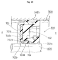
- FIG. 13 Another type of conventional sealing device is shown in Fig. 13. As is shown in Fig. 13, another type of conventional sealing device 700 is designed to seal a distance or a gap between an annular housing 900 and a shaft 800, preventing a fluid (oil or the like) to be sealed from leaking from a fluid (oil or the like) side O to an air-side A.
- the conventional sealing device 700 has a rigid (metal) annular casing 701 with a rubber sealing member 702 in one body, and with a resin sealing member 703 which is placed between and held by the annular rigid casing 701 and the rubber sealing member 702.
- the rubber sealing member 702 comprises a radially outer peripheral sealing portion 702b which firmly contacts with the hausing to seal a fluid, a sealing lip 702a which slides on and seals the shaft 800, and a radially extending portion 702c which connects to the radially outer peripheral sealing portion 702b, in one body.
- the resin sealing member 703 backs up a base portion 702d of the sealing lip 702a of the rubber sealing member 702 to prevent the base portion 702d from over deformation caused by pressure from the oil-side O, and also slides on and seals the shaft 800.
- the resin sealing member 703 is preferably made of a resin material having certain degree of bending resistance (or flexibility) in order to secure the shape thereof and the engagement with the shaft 800.
- resin materials having specific flexibility are fluoro polymers such as PTFE (Polytetrafluoroethylene) or the like.
- the resin sealing member 703 can not give a strong tension to all over the sealing periphery of the surface of the shaft. Oil leakage tends to occur due to the lack of tension in resin sealing member.
- grooves 704 having a pumping property are usually formed on the sealingly engaging surface of the resin sealing member 703.
- the groove 704 has a structure to give the resin sealing member 703 a pumping function to pump oil back to oil-side O at the time there is relative rotational movement between the sealing device 700 and the shaft 800.
- the grooves 704 are preferably formed in a screw type manner, thereby providing the sealing device 700 with one way pumping effect.
- a plurality of grooves 704 are preferably formed in a concentric circular manner, thereby exerting moderate pumping effect on the sealing device even in both normal and reverse rotations of the shaft 800. The distance or the gap between the shaft 800 and the hausing 900 is effectively sealed by the sealing device mentioned above.
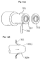
- the resin sealing member 703 has been prepared to form the helical groove by using thread cutting means, on a surface 707 of an end portion of a resin tubular body 705, which has a predetermined inner and outer diameter made of resin material such as PTFE (Polytetrafluoroethylene or the like); and then cutting off the end portion by a cutting means 706 from the resin tubular body 705 to make a washer-like plain sealing member 703 with helical groove (as shown in Fig. 14A).
- Helical groove can be made by press forming processes as well as cutting processes.
- a pressing tool 800J which has an approximately same outer diameter as that of the shaft 800 to be sealed, is inserted, by using a press machine or the like, into an inner hollow bore of the thus obtained washer-like plain sealing member 703, thereby bending a lip portion thereof at a predetermined angle and forming a sealing lip portion 703a which is designed to slide on and seal the shaft 800 (as shown in Fig. 14B).
- washer-like sealing members having large inner bore have a shortcoming in process because the productivity of the conventional sealing members 703 decreases with increasing in wall thickness of the resin tubular body 705, and the material cost also becomes large with increasing in wall thickness.
- resin materials such as PTFE or the like have an extremely low in elastic elongation limit compared with elastomers usually having high elasticity, so the resin sealing member without bending process mentioned above, are prone to be inadvertently distorted or in some cases broken.
- It is therefore an object of the present invention is to provide a sealing device having an excellent anti-abrasion property.
- Another object of the invention is to provide a sealing device having an excellent sealing property in long use.
- a still another object of the present invention is to provide a process of making a sealing device having an excellent anti-abrasion property.
- a further object of the invention is to provide a process of making a sealing device having an excellent anti-abrasion property at low cost.
- a sealing device comprising; a rigid annular casing provided with an elastic rubber like sealing lip disposed in an axial direction of the sealing device, and said sealing lip having a frustoconical air-side surface and having a frustoconical oil-side surface; and a harder helical portion disposed on said frustoconical air-side surface, the hardness of said harder helical portion being harder than the hardness of said sealing lip.
- the harder helical portion on the inner surface of the frustoconical air-side surface is formed by hardness variation making means which forms the harder portion on the surface of elastic rubber or rubber like materials.
- Another objects of the present invention are achieved by providing a process for making a sealing device, comprising the steps of; preparing a foreproduct of said sealing device having a rigid annular casing, a molded elastomeric member bonded to said casing and a sealing lip defined by a frustoconical air-side surface and a frustoconical oil-side surface; radiating radiation ray on said frustoconical surface to form said harder helical portion.
- the harder helical portion or harder portion can be obtained by inducing chemical reaction in rubber compositions. Chemical reactions can be induced by irradiation of radiation ray.
- the thus obtained harder portions have a pumping function to pump back oil or fluid to be sealed to oil or fluid side to give sealing devices excellent sealing properties.
- Said radiation ray is preferably an electron beam.
- Another object of the present invention can be achieved by providing an additional sealing member comprising thermoplastic elastomer placed between a main rubber sealing lip and a rigid annular casing, said additional sealing member having a harder portion on its sealing surface.
- a process for making a sealing device having the additional sealing member comprising the steps of; preparing a sheet or a washer-like annular member made of a composition comprising thermoplastic elastomer;
- the harder portion can be obtained by inducing chemical reaction in thermoplastic elastomer compositions. Chemical reactions can be induced by irradiation of radiation ray.
- the thus obtained harder portion has a pumping function to pump back oil or fluid to be sealed to oil or fluid side to give sealing devices excellent sealing properties.
- Thermoplastic elastomer is used as a material of the additional sealing member in the sealing device. On the specific area of the surface of the additional sealing member, radiation ray is irradiated to change the properties of the surface of the sealing member.
- the properties of the specific area of the surface of the sealing member can be varied selectively and arbitrarily so that, by using these method, the changes in flexibility of the sealing lip portion can be carried out somewhat arbitrarily, or fluid or oil retention can also be achieved by forming minute convexo-concave configuration in the sealing region which contacts with the shaft to be sealed, or seal or drain of oil can also be achieved by designing the shape and configuration of the specific area.
- the specific area of the sealing surface of the sealing member is preferably irradiated by radiation ray.
- convexo-concave configuration is formed on the irradiated sealing surface of the sealing lip.
- Sealing member is a washer-like annular member, which is preferably made of thermoplastic elastomer composition, and the inner diameter of the sealing member is bent in the axial direction thereof at the time the sealing device is mounted on the shaft, and the radially inner peripheral surface of the sealing member is used as a sealing which slide on and seal the shaft.
- Said radiation ray is preferably an electromagnetic wave.
- Said thermoplastic elastomer can preferably be selected from the group of fluorothermoplastic-based elastomers.
- washer-like sealing member is preferably made of a composition comprising thermoplastic elastomer, and radiation ray is radiated on a specific region thereof to cause physical and chemical changes in the elastomer.
- Fig.1 is a fragmentary cross-sectional view showing the sealing device 1 of the present invention and Fig.2 is a cross-sectional view taken along the line X-X' of Fig. 1.
- the sealing device 1 comprises a rigid annular casing (a part of which is shown as numerical reference 2) made, for example, by stamping of a sheet metal blank, and an annular sealing lip 3. Similar to the conventional design as shown in Fig. 10, the rigid annular casing 2 has a tubular mounting portion (not shown) and a bonding flange 2. The annular sealing lip 3 is bonded to the bonding flange 2, and engages with a shaft (not shown) to slide and seal.
- the sealing device 1 also comprises a conventional dust lip 6 which prevents contaminants from entering into oil-side O from air-side A.
- the "oil-side” O is a nearer side to where oil or fluid to be sealed is placed
- the "air-side” A is a nearer side to an opposite direction of the "oil-side” O.
- the frustoconical surface 11 facing to the oil-side O will be referred to as the "oil-side” surface and the opposite surface 10 facing to the air-side A will be referred to as the "air-side” surface.
- the annular sealing lip 3 is, for example, defined by a pair of frustoconical surfaces 10 and 11 meeting with each other to form a sharp sealing edge 12.
- a conventional garter spring 4 is mounted within a spring groove 5 formed on the outer periphery of the annular sealing lip 3, and urges the main annular sealing lip 3 toward the shaft (not shown).
- the sealing lip 3 is made of rubber composition comprising rubber such as, for example, acrylic rubber (acrylic ester-based polymers), fluoro rubber (vinylidene fluoride-based, tetrafluoroethylene-propylene-based, tetrafluoroethylene-perfluoroalkylvinylether-based polymers), NBR (acrylonitrile-butadiene-based rubbers, hydrogenated acrylonitrile-butadiene-based rubbers), EPDM (ethylene-propylene-based rubbers), natural rubber or isoprene rubber or the like. Conventional fillers and additives can also be added in these rubbers. These rubbers or rubber compositions have a tendency to be cross-linked when radiation ray is radiated thereon.
- acrylic rubber acrylic ester-based polymers
- fluoro rubber vinylene fluoride-based, tetrafluoroethylene-propylene-based, tetrafluoroethylene-perfluoroalkylvinylether-based
- Radiation ray includes, in the present invention, all electromagnetic waves and corpuscular beams such as electromagnetic waves or electron beams. Electron beam is preferably used in the present invention. Radiation energy and radiation dose is also chosen so as to induce cross-linking in these rubbers, so as not to induce decomposition in these rubbers.
- the frustoconical air-side surface 10 is irradiated by radiation ray having a predetermined energy and time, to form a harder helical portion 7 on the surface 10 as shown in Fig. 1.
- a mask which has a plurality of helical slits is preferably placed on the frustoconical air-side surface 10 and then radiation ray is irradiated over the mask at a predetermined radiation energy. and at a predetermined exposure dose.
- helical means a shape of the harder portion which has various elongated shapes such as string like, linear, rectangular, triangular, trapezoid, circular, screw or the like.
- the number and the shape of harder helical portions, or its allocation on the surface 10, can be selected freely.
- the angle of the intersection between the long direction of the helical portion 7 and the edge line 12 is also selected freely.
- Fig.3 is a schematic view showing a part of a radially inner surface of the sealing lip 3, which is in a state of using namely there is a relative movement between the sealing lip 3 and the shaft (not shown).
- the softer portion 9 which is non-irradiated is tend to be elongated compared with the harder portion 7, which is irradiated and having a tendency not to be elongated, by the friction, in the circumference direction, between the inner tip 12 of the sealing lip 3 and the shaft (not shown).
- the elongated softer portions 9 become concave shape grooves 8
- the non-elongated harder portions 7 become convex shape ribs.
- These convex shape ribs 7 work like a conventional ribs 406 of Fig. 11, to give the sealing device a pumping effect, to pump oil or fluid back to oil or fluid side O to effectively seal oil or fluid.
- the sealing lip having harder portions is snugly fitted with all around the outer periphery of the shaft to prevent oil from leaking through an interface between the sealing lip and the shaft, because no- or a little deformation or no grooves are there in the surface of the sealing lip, resulting in no oil leak from oil-side to air-side even at the time of no relative movement between the sealing lip and the shaft.
- Hardness of the harder helical portion can be regulated freely by selecting exposure dose, kinds of radiation rays and rubber composition of the sealing lip.
- the irradiated rubber portions have higher in hardness and, thereby, are less susceptible to be abraded when compared to the conventional sealing lip having a convex ribs which have lower in hardness when compared with the irradated rubber portion, and protruding from the surface of the frustoconical air-side surface; giving sealing devices an excellent sealing property in long use. There is also no need to make ribs on molds for molding sealing devices, so manufacturing, designing and processing cost can also be cut substantially.
- portions - harder and softer portions - are provided, but some portions respectively having various degree of hardness can also be provided in accordance with various purposes and usages.
- Fig.4 (Chart Table) shows test results. Vinylidene fluoride-hexafluoropropylene rubber containing conventional MT carbon black and curatives was used as the rubber of sealing lip. The hardness of the rubber was measured using JIS A hardness meter at 25°C. Electron beam having 250 keV was used. As is shown in Chart Table 4, the hardness of the rubber irradiated were higher than that of non-irradiated portion by 6 to 7 points.
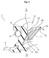
- the configuration of the sealing device of Second Embodiment is similar to the First Embodiment except an additional so-called flat surface in the sealing lip (as shown in Fig.5). Some reference numerals used in Fig.5 are same in Fig.1.
- the sealing lip is made of the same kind of rubber composition mentioned in First Embodiment.
- This type of sealing device 1 has a frustoconical air-side surface 10 and a frustoconical oil-side surface 11, and a third annular substantially frustoconical (or flat) surface 13 placed between the frustoconical air-side surface 10 and the frustoconical oil-side surface 11.
- annular edge lines 14 and 15 which are defined by the frustoconical oil-side surface 11 and the third flat surface 13, and the frustoconical air-side surface 10, respectively as is shown in Fig.5.
- the third annular flat surface 13 has a predetermined width W and slidably and sealingly engages with a shaft (not shown) to be sealed.
- the flat surface 13 is shown like a frustoconical surface having a diameter thereof gradually increasing from the oil-side O to the air-side A.
- the third frustoconical surface 13 has an excellent resistance to abrasion against the shaft because of the surface 13 having, in the surface thereof, higher hardness portions which is harder in abrasion, achieving an excellent sealing properties in its long use.
- all the flat surface 13 is snugly fitted with the surface of the shaft because there is no protruded ribs in the surface 13.
- Said harder portion being harder than the hardness of said thermoplastic elastomer sealing member, and said harder portion acts like a conventional pumping rib when there is a relative movement between said sealing portion and said shaft.
- Third to Fifth Embodiment also relate to the process of the above sealing devices.
- a process of manufacturing a sealing member 101 (in Fig.7A), will be explained.
- the sealing member 101 of Third Embodiment can be used in place of the sealing member 703 of the conventional sealing device 700 in Fig.13. Accordingly, configuration and processing of the sealing device of the present invention is similar to the conventional sealing device as shown in Fig. 13, except the sealing member 703 in Fig. 13.
- the sealing member 101 of the present invention is made of thermoplastic elastomer composition.
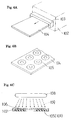
- Thermoplastic elastomer composition can be extruded from a sheet die.
- a sheet 104, from which the sealing member is made, can be continuously manufactured by using both an extruder 102 and a sheet die 103 combined (as shown in Fig.6A).
- Radiation ray is used as the hardness variation making means.
- the radiation ray having an energy of from about 150eV to about 10 MeV can be preferably used.
- radiation ray irradiates the surface of thermoplastic elastomer composition, radiation effects (cross-linking or the like) are induced in thermoplastic elastomer composition, and hardness of thermoplastic elastomer composition irradiated becomes higher than that of non-irradiated portions, due to the cross-linking reaction or the like at the portion the beam is radiated in the shape of helical. circular or the like.
- Exposure dose of radiation ray on the composition is usually in the range of about 5 Mrad to about 100 Mrad, preferably, about 5 Mrad to about 70 Mrad.
- the sheet 104 extruded from the sheet die 103 is cut in a shape of a doughnut (105) by, for example, press cutting process, to make a washer-like annular member 105 (Fig.6).
- annular member 105 is covered with a mask 107 having a plurality of apertures 106 having predetermined pattern, and then radiation ray 109 is irradiated onto the surface of the annular member 105 using radiation irradiator 108, thereby mechanical properties of the irradiated regions of the annular member become to be a different from that of a region non-irradiated (as shown in Fig.6C).
- Shape of the apertures can take various patterns such as helical, spiral or vortical, a plurality of concentric circles, or a screw.
- thermoplastic elastomer composition by irradiation of radiation ray 109.
- Irradiation of radiation ray enables thermoplastic elastomer composition to have higher degree of cross-linking portion (or cross-linking structures) than other portion non-irradiated. With changing these cross-linking structures, hardness and modulus of elasticity of the thermoplastic elastomer composition, which is irradiated by radiation ray 109, is also at the same time led to high.
- Thermoplastic elastomer such as block type fluorothermoplastic elastomer or the like is preferably used as one of a composition for sealing member 101.
- Thermoplastic elasomer has both a soft segment and hard segment in its composition.
- the soft segment (fluoro rubber) in the block type fluoro thermoplasitc elastomer are vinylidenefluoride-hexafluoropropylene-tetrafluoroethylene terpolymer or the like can be used, and examples of the hard segment (fluoro plastic) are polyvinylidene fluoride, tetrafluoroethylene-ethylene copolymer or the like.
- Polymer composition comprising conventional carbon black and/or other additives can be used as a material for the sealing member 101.
- Ionizing radiation having specific frequency band which effectively can cause changes in polymer properties is preferably used in the present invention.
- Electron ray having energy of about 150 eV to about 10 MeV is also preferably used.
- electron ray having high energy is necessary to be used.
- sealing member having thin in thickness is used, electron ray having energy not more than about 300 keV can be used.
- cross-linking reaction can be completed in less than about one (1) second in the case electron ray is used.
- irradiation is carried out in an atmosphere of vacuum or inactive gas such as nitrogen (N 2 ) or the like. Irradiation process can be carried out in a continuous process line, so productivity of the sealing member of the present invention can be extremely improved when compared with such a conventional cutting process as shown in Fig.14A and 14B.
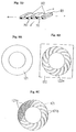
- Fig.7A, 7B, 7C and 7D show a sealing member 101 of the present invention and a sealing device 25.
- Fig.7A is a perspective view showing the sealing member 101 which is irradiated by radiation ray
- Fig.7B is an enlarged perspective view of the portion of D1 in Fig.7A
- Fig.7C is a fragmentary cross sectional view showing a sealing device 25 having the sealing member 101 in place of a conventional sealing member 703 in Fig. 13.
- Fig. 7D is an enlarged perspective view of the portion of D3 in Fig.7C.
- the sealing member 101 has two portions of irradiated portion R1 and non-irradiated portion R2 respectively by irradiation of radiation ray, thereby patterned distribution of a degree of cross-linking, namely, patterned distribution of the elasticity are there on the surface of the sealing member 101.
- each non-irradiated portion R2 is disposed in a shape of a plurality of concentric circles as is shown in Fig.7A and 7B.
- the sealing device 25 is mounted at an annular gap between the housing 350 and the shaft 250.
- radially inner portion 101a of the sealing member 101 bends toward the axial direction with enlarging its radially inner portion, then the portion facing to the shaft 250 becomes a sealing portion 101b (in Fig.7C).
- the sealing member has no need to use conventional pressing prodedure as shown in Fig. 14B, because thermoplastic elastomer composition is easily elongated than the conventional sealing member made of resin such as PTFE.
- the grooves M1 and M1 show pumping function to pump oil back from air-side A to oil-side O, and also have a function to retain oil in the grooves. These functions improve sealing ability of the sealing device 25.
- Sealing members of Fifth Embodiment were made of fluoro thermoplastic elastomer-based composition.
- Diel Thermoplastic T630 manufactured by DAIKIN Co.
- the Diel Thermoplastic flows at under high temperature, but shows rubber like elasticity at under its crystallization temperature.
- Sheets can be continuously obtained using a conventional extruder and sheet (T) die. Washer-like thermoplastic sealing member can be easily manufactured by die cutting or the like from the sheets.
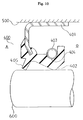
- metal sheet 122 having a plurality of slit patterns as is shown for example in Fig. 8B can be used. Slits 122a are there in the metal sheet 122 as shown in Fig.8B.
- Electron ray can not pass (penetrate) through metal, so a portion of the sealing member 121 covered by the metal sheet is not susceptible to the influence of radiation ray. This phenomena can be effectively used in Fifth Embodiment.
- the cross-hutching regions 121a are highly electron irradiated portions or harder portions by electron ray.
- the regions 121b are non-irradiated portions or softer portions.
- Fig. 9 shows physical (tensile strength at break or the like) properties of the test specimens.
- the specimen were prepared using Diel Thermoplastic T630 (manufactured by DAIKIN Co.) as a fluorothermoplastic elastomer and carbon black (HAF grade carbon black, 30 weight parts based on 100 weight parts of elastomer).
- the specimen were irradiated with various exposure dose. There is no changes in modulus of elasticity at 100 % elongation except strength at break in the case of base polymer as shown in Chart Table 9.
- the thus obtained sealing members 121 have grooves at non- or a little-irradiated portion and show pumping function (sealing function) when the thus obtained sealing members is mounted on the shaft 250.
- the thus obtained sealing member 121 can be used in a sealing device 25 in Fig.7C.
- hardness changing means of changing hardness in rubber materials by using hardness changing means of changing hardness in rubber materials, hardness distribution on a surface of a sealing lip can be made helically.
- a softer portion other than a harder portion tends to deform and elongate larger, to form groove like concave helical portion due to friction between the shaft and the sealing lip; that is, the harder portion becomes convex like helical rib showing such same pumping function as conventional helical ribs show.
- the harder portion of the sealing lip has also more resistance to abrasion against the shaft when compared to a conventional rib which has same hardness of sealing lip.
Landscapes
- Engineering & Computer Science (AREA)
- General Engineering & Computer Science (AREA)
- Physics & Mathematics (AREA)
- Fluid Mechanics (AREA)
- Mechanical Engineering (AREA)
- Sealing With Elastic Sealing Lips (AREA)
- Sealing Material Composition (AREA)
Applications Claiming Priority (2)
| Application Number | Priority Date | Filing Date | Title |
|---|---|---|---|
| JP10094099A JPH11270697A (ja) | 1998-03-23 | 1998-03-23 | オイルシール |
| JP9409998 | 1998-03-23 |
Publications (2)
| Publication Number | Publication Date |
|---|---|
| EP0945652A2 true EP0945652A2 (de) | 1999-09-29 |
| EP0945652A3 EP0945652A3 (de) | 2000-05-31 |
Family
ID=14101010
Family Applications (1)
| Application Number | Title | Priority Date | Filing Date |
|---|---|---|---|
| EP99105415A Withdrawn EP0945652A3 (de) | 1998-03-23 | 1999-03-17 | Dichtungsvorrichtung und Verfharen zu seiner Herstellung |
Country Status (3)
| Country | Link |
|---|---|
| US (3) | US6334618B1 (de) |
| EP (1) | EP0945652A3 (de) |
| JP (1) | JPH11270697A (de) |
Cited By (2)
| Publication number | Priority date | Publication date | Assignee | Title |
|---|---|---|---|---|
| EP1239197A1 (de) * | 2001-03-09 | 2002-09-11 | Stefa S.r.l. | Herstellungsverfahren für einen dynamischen Radialwellendichtring |
| CN102417631A (zh) * | 2011-10-31 | 2012-04-18 | 铜陵新特阀门有限责任公司 | 一种用于生产平行式闸阀端面o型密封圈的橡胶胶料及其制备方法 |
Families Citing this family (19)
| Publication number | Priority date | Publication date | Assignee | Title |
|---|---|---|---|---|
| JP2001317635A (ja) * | 2000-05-02 | 2001-11-16 | Toyota Industries Corp | リップ型シール |
| US7025357B2 (en) * | 2001-06-08 | 2006-04-11 | Freudenberg-Nok General Partnership | Shaft seal having lip supports |
| JP2003035373A (ja) * | 2001-07-23 | 2003-02-07 | Toyota Industries Corp | 軸封装置及び該軸封装置を備えた圧縮機、軸封方法 |
| KR100934527B1 (ko) * | 2003-09-19 | 2009-12-29 | 엔오케이 가부시키가이샤 | 밀봉 장치 |
| US7914006B2 (en) * | 2004-07-09 | 2011-03-29 | Baker Hughes Incorporated | Drilling tool with elastomer seal having graded properties |
| JP2006242373A (ja) * | 2004-09-24 | 2006-09-14 | Nok Corp | 密封装置 |
| CN101802466B (zh) * | 2007-09-04 | 2013-06-12 | 株式会社荒井制作所 | 密封装置 |
| JP2009074602A (ja) * | 2007-09-20 | 2009-04-09 | Nok Corp | オイルシール |
| WO2011111630A1 (ja) * | 2010-03-08 | 2011-09-15 | 本田技研工業株式会社 | 自動車用エンジンオイルシール |
| US9322477B2 (en) * | 2010-03-08 | 2016-04-26 | Honda Motor Co., Ltd. | Vehicle transmission oil seal |
| WO2012132731A1 (ja) * | 2011-03-31 | 2012-10-04 | イーグル工業株式会社 | 密封装置及び密封構造 |
| JP5771118B2 (ja) * | 2011-10-28 | 2015-08-26 | カヤバ工業株式会社 | 密封装置及びこの密封装置を備える懸架装置 |
| DE102012001226A1 (de) * | 2012-01-19 | 2013-07-25 | Kaco Gmbh + Co. Kg | Wellendichtung, insbesondere Radialwellendichtung |
| CN104067036B (zh) * | 2012-01-23 | 2016-09-28 | 大金工业株式会社 | 汽车用油封 |
| JP5637172B2 (ja) * | 2012-04-27 | 2014-12-10 | Nok株式会社 | 密封装置 |
| JP5977665B2 (ja) * | 2012-12-14 | 2016-08-24 | Kyb株式会社 | フロントフォーク |
| JP6809847B2 (ja) * | 2016-09-01 | 2021-01-06 | Nok株式会社 | 密封装置 |
| US11988264B2 (en) * | 2021-10-19 | 2024-05-21 | DRiV Automotive Inc. | Hydraulic damper with a baffle |
| JP7804054B2 (ja) * | 2022-02-24 | 2026-01-21 | Nok株式会社 | 密封装置 |
Citations (1)
| Publication number | Priority date | Publication date | Assignee | Title |
|---|---|---|---|---|
| JPS6056618A (ja) | 1983-09-07 | 1985-04-02 | Showa Mfg Co Ltd | 油圧緩衝器の車高調整装置 |
Family Cites Families (13)
| Publication number | Priority date | Publication date | Assignee | Title |
|---|---|---|---|---|
| US3633927A (en) * | 1970-02-11 | 1972-01-11 | Federal Mogul Corp | Molded-lip hydrodynamic shaft seal |
| US3929341A (en) | 1973-12-19 | 1975-12-30 | Federal Mogul Corp | Method of making polytetrafluoroethylene sealing elements with hydrodynamic action |
| US4300777A (en) * | 1980-06-16 | 1981-11-17 | General Motors Corporation | Fluid seal |
| US4705277A (en) * | 1984-11-08 | 1987-11-10 | Microdot Inc. | Hydrodynamic seal |
| US4822058A (en) * | 1987-10-01 | 1989-04-18 | Federal-Mogul Corporation | Radial lip seal |
| EP0357329A3 (de) * | 1988-08-29 | 1991-05-29 | Minnesota Mining And Manufacturing Company | Fluorkohlenstoff-Elastomere, vernetzt mit ionisierender Strahlung |
| US5013052A (en) * | 1989-05-03 | 1991-05-07 | Federal-Mogul Corporation | Oil seal having attached thereto two aligned polytetrafluoroethylene pieces forming seal lips |
| GB2240592A (en) * | 1990-01-24 | 1991-08-07 | Woodville Polymer Eng | Hydrodynamic shaft seals |
| NL9301601A (nl) * | 1993-09-16 | 1995-04-18 | Skf Ind Trading & Dev | Werkwijze voor de vervaardiging van een afdichting voor een wentellager, afdichting voor een wentellager, alsmede een van een dergelijke afdichting voorzien wentellager. |
| JPH08159294A (ja) | 1994-12-02 | 1996-06-21 | Nok Corp | 密封装置 |
| US5759466A (en) * | 1995-05-25 | 1998-06-02 | Nok Corporation | Method of making lip-type oil seals having improved sealing edge |
| JP3367802B2 (ja) | 1995-09-14 | 2003-01-20 | エヌオーケー株式会社 | シール部材の製造方法及び密封装置 |
| DE19619999C2 (de) * | 1996-05-17 | 2000-02-10 | Reinz Dichtungs Gmbh | Verfahren und Form zum Herstellen lippenförmiger Dichtbereiche auf Dichtungskörpern oder Bauteilen |
-
1998
- 1998-03-23 JP JP10094099A patent/JPH11270697A/ja active Pending
-
1999
- 1999-03-17 EP EP99105415A patent/EP0945652A3/de not_active Withdrawn
- 1999-03-23 US US09/274,346 patent/US6334618B1/en not_active Expired - Fee Related
-
2001
- 2001-10-19 US US09/982,206 patent/US6814919B2/en not_active Expired - Fee Related
-
2004
- 2004-08-31 US US10/929,596 patent/US20050023767A1/en not_active Abandoned
Patent Citations (1)
| Publication number | Priority date | Publication date | Assignee | Title |
|---|---|---|---|---|
| JPS6056618A (ja) | 1983-09-07 | 1985-04-02 | Showa Mfg Co Ltd | 油圧緩衝器の車高調整装置 |
Cited By (2)
| Publication number | Priority date | Publication date | Assignee | Title |
|---|---|---|---|---|
| EP1239197A1 (de) * | 2001-03-09 | 2002-09-11 | Stefa S.r.l. | Herstellungsverfahren für einen dynamischen Radialwellendichtring |
| CN102417631A (zh) * | 2011-10-31 | 2012-04-18 | 铜陵新特阀门有限责任公司 | 一种用于生产平行式闸阀端面o型密封圈的橡胶胶料及其制备方法 |
Also Published As
| Publication number | Publication date |
|---|---|
| US6334618B1 (en) | 2002-01-01 |
| JPH11270697A (ja) | 1999-10-05 |
| US20020043770A1 (en) | 2002-04-18 |
| US20050023767A1 (en) | 2005-02-03 |
| EP0945652A3 (de) | 2000-05-31 |
| US6814919B2 (en) | 2004-11-09 |
Similar Documents
| Publication | Publication Date | Title |
|---|---|---|
| US6814919B2 (en) | Sealing device and process for manufacturing the same | |
| US9261195B2 (en) | Energised seal | |
| CN101208548B (zh) | 动态密封件、旋转密封件及制造高温动态密封件的方法 | |
| US3921987A (en) | Shaft seals | |
| US4723833A (en) | Lens mounting assembly and process | |
| US6286839B1 (en) | Ring seal including a core surrounded by a metal jacket | |
| US3995868A (en) | Polytetrafluoroethylene lip seal | |
| CN100436896C (zh) | 密封装置 | |
| JP3745625B2 (ja) | シリンダヘッドガスケット | |
| EP1895208B1 (de) | Öldichtung und verfahren zu dessen herstellung | |
| JP2007503316A (ja) | 保持具付きガスケットの構造 | |
| US6616146B2 (en) | Radial seal arrangement | |
| JP4147629B2 (ja) | シール付き転がり軸受 | |
| DK144251B (da) | Laebetaetning til en rotorende aksel | |
| JP2002047480A (ja) | シール材 | |
| US3921990A (en) | Shaft seals | |
| US20050035556A1 (en) | Annular seal | |
| JP2005221020A (ja) | 密封装置 | |
| KR102576874B1 (ko) | 밀봉장치 및 밀봉장치의 장착방법 | |
| JP3555428B2 (ja) | 密封装置及び密封装置の製造方法 | |
| GB2029913A (en) | Sealing ring assemblies | |
| CN212509526U (zh) | 核电站流体动压型主泵机械密封的浮动密封装置 | |
| JP7474632B2 (ja) | シール部材 | |
| CN112096873A (zh) | 核电站流体动压型主泵机械密封的浮动密封装置 | |
| JP4204758B2 (ja) | 樹脂被覆ゴムガスケットの製造方法 |
Legal Events
| Date | Code | Title | Description |
|---|---|---|---|
| PUAI | Public reference made under article 153(3) epc to a published international application that has entered the european phase |
Free format text: ORIGINAL CODE: 0009012 |
|
| AK | Designated contracting states |
Kind code of ref document: A2 Designated state(s): DE ES FR GB IT SE |
|
| AX | Request for extension of the european patent |
Free format text: AL;LT;LV;MK;RO;SI |
|
| PUAL | Search report despatched |
Free format text: ORIGINAL CODE: 0009013 |
|
| AK | Designated contracting states |
Kind code of ref document: A3 Designated state(s): AT BE CH CY DE DK ES FI FR GB GR IE IT LI LU MC NL PT SE |
|
| AX | Request for extension of the european patent |
Free format text: AL;LT;LV;MK;RO;SI |
|
| 17P | Request for examination filed |
Effective date: 20000427 |
|
| AKX | Designation fees paid |
Free format text: DE ES FR GB IT SE |
|
| RAP1 | Party data changed (applicant data changed or rights of an application transferred) |
Owner name: CARL FREUDENBERG KG |
|
| 17Q | First examination report despatched |
Effective date: 20030801 |
|
| GRAP | Despatch of communication of intention to grant a patent |
Free format text: ORIGINAL CODE: EPIDOSNIGR1 |
|
| STAA | Information on the status of an ep patent application or granted ep patent |
Free format text: STATUS: THE APPLICATION IS DEEMED TO BE WITHDRAWN |
|
| 18D | Application deemed to be withdrawn |
Effective date: 20040922 |