EP0945666A1 - Support isolé thermiquement et méthode de fabrication - Google Patents
Support isolé thermiquement et méthode de fabrication Download PDFInfo
- Publication number
- EP0945666A1 EP0945666A1 EP98302172A EP98302172A EP0945666A1 EP 0945666 A1 EP0945666 A1 EP 0945666A1 EP 98302172 A EP98302172 A EP 98302172A EP 98302172 A EP98302172 A EP 98302172A EP 0945666 A1 EP0945666 A1 EP 0945666A1
- Authority
- EP
- European Patent Office
- Prior art keywords
- thermal
- insulating member
- thermal insulated
- thermal insulating
- supporting member
- Prior art date
- Legal status (The legal status is an assumption and is not a legal conclusion. Google has not performed a legal analysis and makes no representation as to the accuracy of the status listed.)
- Granted
Links
Images

Classifications
-
- F—MECHANICAL ENGINEERING; LIGHTING; HEATING; WEAPONS; BLASTING
- F16—ENGINEERING ELEMENTS AND UNITS; GENERAL MEASURES FOR PRODUCING AND MAINTAINING EFFECTIVE FUNCTIONING OF MACHINES OR INSTALLATIONS; THERMAL INSULATION IN GENERAL
- F16L—PIPES; JOINTS OR FITTINGS FOR PIPES; SUPPORTS FOR PIPES, CABLES OR PROTECTIVE TUBING; MEANS FOR THERMAL INSULATION IN GENERAL
- F16L59/00—Thermal insulation in general
- F16L59/12—Arrangements for supporting insulation from the wall or body insulated, e.g. by means of spacers between pipe and heat-insulating material; Arrangements specially adapted for supporting insulated bodies
- F16L59/135—Hangers or supports specially adapted for insulated pipes
Definitions
- the present invention relates to improvements in thermal insulated supports used for pipings, tanks, heat exchangers and pumps, for example, when used in conjunction with low temperature liquids, and a method for fabricating the same.
- thermal insulated supports for pipes transporting low temperature liquids have been widely utilized.
- a thermal insulated supporting member formed in a predetermined shape at a predetermined position on an outer peripheral surface of the piping at the job site
- a semicylindrical thermal insulating material in which there is provided a cut-out opening portion formed in accordance with the shape of the thermal insulated supporting member, is mounted at a location adjacent the thermal insulated supporting member.
- a foam system such as a rigid polyurethane foam, is dispensed into a gap between the cut-out opening portion of the semicylindrical thermal insulating material and the thermal insulated support.
- the foam system is subsequently foamed and solidified.
- dispensing, foaming and filling of the foam system into the gap between the cut-out opening portion of the semicylindrical thermal insulating material and the thermal insulated supporting member requires a number of additional steps, such as mounting of dispensing molds, dismounting the molds, trimming of foam, and application of a vapor barrier, for example.
- the foam generating reaction of the foam dispensed into the gap between the cut-out opening portion of the semicylindrical thermal insulating material and the thermal insulated supporting member at the application site is exothermic. Accordingly, cooling to an ambient temperature results in stresses and strains being produced in the foam and remaining therein. Consequently, when the piping is cooled, the foam is exposed to a low temperature and hence the remaining stresses and strains are accentuated and may exceed the tolerance limits, which gives rise to serious problems such as cracking and peeling, for example.
- JU-B-3-17119 there is disclosed a thermal insulated support, around which thermal insulating material is molded directly in contact with the periphery of the part, wherein the heat insulating support joint the semicylindrical thermal insulating material.
- stresses and strains also remain between the thermal insulating material and the thermal insulated supporting member as described above, which may lead to cracking and peeling in the heat insulating cylindrical foam when exposed to a low temperature.
- An object of the present invention is to provide a thermal insulated support which address the problems associated with the prior art, and a method for fabricating the same.
- a thermal insulated support according to the present invention in which a thermal insulated supporting member having an inner peripheral surface, which has a same radius of curvature as a thermal insulating member is mounted on a cut-out opening portion of the thermal insulating member, is characterized in that a preformed thermal insulating member is put between the thermal insulating member and the thermal insulated supporting member.
- the method for fabricating the thermal insulated support according to the present invention in which, after having mounted a thermal insulated supporting member at a predetermined position of thermal insulating member forming molds, foam system of a thermosetting plastics foam material is dispensed into a vacant space in the frames to be foamed and solidified, is characterized in that as said thermal insulated supporting member, one around which a preformed thermal insulating member is mounted, is used.
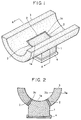
- Figs. 1 and 2 show a preferred embodiment of a thermal insulated support according to the present invention for a piping.
- the thermal insulated support indicated in the same figures is composed of a thermal insulated supporting member 1 made of a high density synthesized plastic foam material; a preformed thermal insulating member 2 made of a plastic foam adhered on an upper periphery of the thermal insulated supporting member 1; a semicylindrical insulating member 3 formed by foaming and solidifying plastic foam system dispensed into molds so that it is joined to an upper peripheral portion of the thermal insulated supporting member 1, putting the preformed thermal insulating member 2 therebetween; and a base plate 4 joined on a bottom surface of the thermal insulated supporting member 1.
- the thermal insulated supporting member 1 is mounted on a cut-out opening portion 3c through the preformed thermal insulating member 2 and has an inner peripheral surface 1a, which has a same radius of curvature as the thermal insulating member.
- Fig. 1 is a perspective view of the thermal insulated support for a piping according to this embodiment of the present invention
- Fig. 2 is a cross-sectional view along a line indicated by A-A in Fig. 1.
- reference numeral 1 is a thermal insulated supporting member for a piping constituting a thermal insulated support for a piping.
- this thermal insulated supporting member 1 for a piping high density plastic foam, woody material, high density calcium silicate, etc. having an excellent thermal insulating properties and a high load bearing strength can be selectively used appropriately according to an object of use.
- a preformed thermal insulating member 2 is made of a plastic foam adhered on the upper periphery of thermal insulated supporting member 1.
- the thickness of this preformed thermal insulating member 2 is not specifically restricted, but a thickness about from 5 to 30mm is suitable.
- the width thereof may be equal to the width, over which the thermal insulating member is in contact with the thermal insulated supporting member or may be smaller than the width above-mentioned as indicated in Fig. 3.
- a semicylindrical thermal insulating member 3 formed by foaming and solidifying plastic foam system dispensed into molds in a state where the preformed thermal insulating member 2 is put therebetween is joined in one body to the upper periphery of the thermal insulated supporting member 1.
- thermosetting plastic foam such as polyurethane foam, polyisocyanurate foam, etc. can be used selectively.
- 4 is a base plate joined on a bottom surface of the thermal insulated supporting member 1.
- the shape of the thermal insulated supporting member 1 is not restricted to those indicated in Figs. 1 to 3, but any shape can be selectively used appropriately according to an object of use.
- Fig. 4 indicates an example thereof.
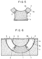
- the shape of the insulating member is not restricted to the semicylindrical form, but it may be a multi-divided cylindrical form such as a cylindrical form divided into three, and others, as indicated in Fig. 5.
- the vapor barrier member 5 may be mounted on the outer periphery 3a of the semicylindrical thermal insulating member 3 and in addition, the reinforcing member 6 may be mounted in one body on the inner peripheral surface 3b.
- the vapor barrier an aluminium foil, composite sheet such as an aluminium foil and a plastic sheet or a glass cloth, etc., and asphalt roofing can be used.
- the reinforcing material a sheet member having a strength higher than the thermosetting foam such as glass cloth, asphalt roofing, asphalt paper, etc. can be used.
- Fig. 6 shows an example of the method for fabricating the thermal insulated support for a piping.
- thermosetting plastic foam system is dispensed into a vacant space 9 within the molds to form the thermal insulating member 3 foamed and solidified and at the same time to make the thermal insulating member 3 adhered to the thermal insulated supporting member 1 owing to self adhesivity.
- the vapor barrier member and the reinforcing member can be joined with the heat insulating member 3 in one body on the outer peripheral surface and the inner peripheral surface thereof, respectively, by mounting the vapor barrier member 5 on the inner surface 9a of the vacant space 9 within the forming molds and the reinforcing member 6 on the inner surface 9b, and dispensing the foam system into the vacant space to be foamed and solidified.
- the thermal insulated supporting member 1 since the preformed insulating member 2 adhered to the upper periphery of the thermal insulated supporting member 1, and the thermal insulating member 3 are integrated, and there exists no distortion due to remaining thermal stress at the joining portion of the thermal insulating member 3 to the thermal insulated supporting member 1, no phenomena harmful to the insulation such as cracking, peeling, etc. are produced by temperature variations in practice.
- thermal insulated support since the thermal insulated supporting member, preformed thermal insulating member adhered to it and thermal insulating member are integrated so that no remaining stress and strain exist at the joining portion, even if it is exposed to temperature variations in practice, no phenomena harmful to insulation such as cracking, peeling, etc. are produced and an excellent insulating properties can be maintained over a long period.
- thermosetting plastic foam system is dispensed into the vacant space within the molds, on which the thermal insulated supporting member is mounted, to form the thermal insulating member by foaming and solidifying it, with which the thermal insulated supporting member can be integrated in one fabrication step, so that an extremely great economical advantage can be obtained as an efficient method for fabricating the thermal insulated support.
Landscapes
- Engineering & Computer Science (AREA)
- General Engineering & Computer Science (AREA)
- Mechanical Engineering (AREA)
- Thermal Insulation (AREA)
Priority Applications (1)
| Application Number | Priority Date | Filing Date | Title |
|---|---|---|---|
| EP98302172A EP0945666B1 (fr) | 1998-03-24 | 1998-03-24 | Méthode de fabrication d'un support isolé thermiquement |
Applications Claiming Priority (1)
| Application Number | Priority Date | Filing Date | Title |
|---|---|---|---|
| EP98302172A EP0945666B1 (fr) | 1998-03-24 | 1998-03-24 | Méthode de fabrication d'un support isolé thermiquement |
Publications (2)
| Publication Number | Publication Date |
|---|---|
| EP0945666A1 true EP0945666A1 (fr) | 1999-09-29 |
| EP0945666B1 EP0945666B1 (fr) | 2003-01-22 |
Family
ID=8234731
Family Applications (1)
| Application Number | Title | Priority Date | Filing Date |
|---|---|---|---|
| EP98302172A Expired - Lifetime EP0945666B1 (fr) | 1998-03-24 | 1998-03-24 | Méthode de fabrication d'un support isolé thermiquement |
Country Status (1)
| Country | Link |
|---|---|
| EP (1) | EP0945666B1 (fr) |
Cited By (1)
| Publication number | Priority date | Publication date | Assignee | Title |
|---|---|---|---|---|
| CN110375154A (zh) * | 2019-07-30 | 2019-10-25 | 江苏中圣管道工程技术有限公司 | 预制成品保温管用固定管托 |
Citations (4)
| Publication number | Priority date | Publication date | Assignee | Title |
|---|---|---|---|---|
| US3980262A (en) * | 1972-03-09 | 1976-09-14 | Rilco, Division Sadler Industrial Services, Inc. | Pipe insulation load bearing support |
| DE3809744A1 (de) * | 1988-03-23 | 1989-10-05 | Korff & Co | Mehrteilige rohrschelle |
| EP0638756A1 (fr) * | 1993-08-05 | 1995-02-15 | Automobiles Peugeot | Dispositif de montage d'un tube sur un support |
| GB2315107A (en) * | 1996-07-06 | 1998-01-21 | Atlantic Plastics Ltd | Insulating pipe support |
Family Cites Families (1)
| Publication number | Priority date | Publication date | Assignee | Title |
|---|---|---|---|---|
| JPS6045986U (ja) * | 1983-09-07 | 1985-04-01 | 株式会社アスク | 配管装置 |
-
1998
- 1998-03-24 EP EP98302172A patent/EP0945666B1/fr not_active Expired - Lifetime
Patent Citations (4)
| Publication number | Priority date | Publication date | Assignee | Title |
|---|---|---|---|---|
| US3980262A (en) * | 1972-03-09 | 1976-09-14 | Rilco, Division Sadler Industrial Services, Inc. | Pipe insulation load bearing support |
| DE3809744A1 (de) * | 1988-03-23 | 1989-10-05 | Korff & Co | Mehrteilige rohrschelle |
| EP0638756A1 (fr) * | 1993-08-05 | 1995-02-15 | Automobiles Peugeot | Dispositif de montage d'un tube sur un support |
| GB2315107A (en) * | 1996-07-06 | 1998-01-21 | Atlantic Plastics Ltd | Insulating pipe support |
Cited By (1)
| Publication number | Priority date | Publication date | Assignee | Title |
|---|---|---|---|---|
| CN110375154A (zh) * | 2019-07-30 | 2019-10-25 | 江苏中圣管道工程技术有限公司 | 预制成品保温管用固定管托 |
Also Published As
| Publication number | Publication date |
|---|---|
| EP0945666B1 (fr) | 2003-01-22 |
Similar Documents
| Publication | Publication Date | Title |
|---|---|---|
| EP0457787B1 (fr) | Enveloppe d'isolation thermique | |
| EP0363042B1 (fr) | Structure composite renforcée | |
| US7815269B2 (en) | Refrigerator | |
| KR101180742B1 (ko) | 극저온 액체저장탱크의 단열 패널 및 이를 갖는 단열 구조체 | |
| US9291308B2 (en) | LNG container with a connecting device which connects a secondary impermeable barrier to a load bearing structure | |
| JPH11513465A (ja) | 断熱性強化パネル | |
| KR20140121340A (ko) | 극저온 물질 운반선의 화물창 | |
| CN102398735A (zh) | 隔绝容器 | |
| US20180328648A1 (en) | Heat insulating material and insulating case for refrigerator | |
| KR20150039597A (ko) | 직선 굴곡형 멤브레인 시트를 이용한 극저온 물질 운반선의 화물창 | |
| EP0945666B1 (fr) | Méthode de fabrication d'un support isolé thermiquement | |
| EP0440031B1 (fr) | Réservoir isolé sous vide contre la chaleur | |
| US4923075A (en) | Thermostatically controllable tank container | |
| KR101225180B1 (ko) | 액화천연가스 저장탱크용 단열 패널 및 이를 포함하는 단열구조체 | |
| KR101870358B1 (ko) | 허니컴 패널을 이용한 대형 위성 수신 안테나 제조공법 | |
| JP4985991B2 (ja) | 低温液体用モジュラ容器 | |
| JP2005299697A (ja) | 真空断熱パネルおよびその製造方法 | |
| CN117175115A (zh) | 一种电池包的下壳及保温电池包 | |
| EP2401447B1 (fr) | Élément paroi et procédé de production de l'élément | |
| JPH06194031A (ja) | 断熱箱体 | |
| JP3396591B2 (ja) | 断熱支持装置の製造方法 | |
| US4499894A (en) | Passive solar water heater support box | |
| US6070807A (en) | Water geyser assembly | |
| KR101280326B1 (ko) | 선박용 저장탱크의 내벽구조 | |
| JP2002240888A (ja) | 低温タンク船のタンク防熱工法 |
Legal Events
| Date | Code | Title | Description |
|---|---|---|---|
| PUAI | Public reference made under article 153(3) epc to a published international application that has entered the european phase |
Free format text: ORIGINAL CODE: 0009012 |
|
| AK | Designated contracting states |
Kind code of ref document: A1 Designated state(s): GB NL |
|
| AX | Request for extension of the european patent |
Free format text: AL;LT;LV;MK;RO;SI |
|
| 17P | Request for examination filed |
Effective date: 19991012 |
|
| AKX | Designation fees paid |
Free format text: GB NL |
|
| REG | Reference to a national code |
Ref country code: DE Ref legal event code: 8566 |
|
| 17Q | First examination report despatched |
Effective date: 20011024 |
|
| RTI1 | Title (correction) |
Free format text: METHOD FOR FABRICATING A THERMAL INSULATED SUPPORT |
|
| GRAH | Despatch of communication of intention to grant a patent |
Free format text: ORIGINAL CODE: EPIDOS IGRA |
|
| GRAH | Despatch of communication of intention to grant a patent |
Free format text: ORIGINAL CODE: EPIDOS IGRA |
|
| GRAA | (expected) grant |
Free format text: ORIGINAL CODE: 0009210 |
|
| AK | Designated contracting states |
Kind code of ref document: B1 Designated state(s): GB NL |
|
| REG | Reference to a national code |
Ref country code: GB Ref legal event code: FG4D |
|
| PLBE | No opposition filed within time limit |
Free format text: ORIGINAL CODE: 0009261 |
|
| STAA | Information on the status of an ep patent application or granted ep patent |
Free format text: STATUS: NO OPPOSITION FILED WITHIN TIME LIMIT |
|
| 26N | No opposition filed |
Effective date: 20031023 |
|
| PGFP | Annual fee paid to national office [announced via postgrant information from national office to epo] |
Ref country code: NL Payment date: 20090315 Year of fee payment: 12 |
|
| PGFP | Annual fee paid to national office [announced via postgrant information from national office to epo] |
Ref country code: GB Payment date: 20090318 Year of fee payment: 12 |
|
| REG | Reference to a national code |
Ref country code: NL Ref legal event code: V1 Effective date: 20101001 |
|
| GBPC | Gb: european patent ceased through non-payment of renewal fee |
Effective date: 20100324 |
|
| PG25 | Lapsed in a contracting state [announced via postgrant information from national office to epo] |
Ref country code: NL Free format text: LAPSE BECAUSE OF NON-PAYMENT OF DUE FEES Effective date: 20101001 |
|
| PG25 | Lapsed in a contracting state [announced via postgrant information from national office to epo] |
Ref country code: GB Free format text: LAPSE BECAUSE OF NON-PAYMENT OF DUE FEES Effective date: 20100324 |