EP0945976A2 - Elektrischer Schaltkreis - Google Patents
Elektrischer Schaltkreis Download PDFInfo
- Publication number
- EP0945976A2 EP0945976A2 EP99610013A EP99610013A EP0945976A2 EP 0945976 A2 EP0945976 A2 EP 0945976A2 EP 99610013 A EP99610013 A EP 99610013A EP 99610013 A EP99610013 A EP 99610013A EP 0945976 A2 EP0945976 A2 EP 0945976A2
- Authority
- EP
- European Patent Office
- Prior art keywords
- connecting point
- relays
- activated state
- relay
- connects
- Prior art date
- Legal status (The legal status is an assumption and is not a legal conclusion. Google has not performed a legal analysis and makes no representation as to the accuracy of the status listed.)
- Withdrawn
Links
- 230000001939 inductive effect Effects 0.000 claims abstract description 17
- 230000009849 deactivation Effects 0.000 claims description 9
- 230000004913 activation Effects 0.000 claims description 4
- 230000001965 increasing effect Effects 0.000 abstract description 3
- 230000008859 change Effects 0.000 description 7
- 230000006872 improvement Effects 0.000 description 4
- 230000008901 benefit Effects 0.000 description 3
- 230000000717 retained effect Effects 0.000 description 3
- 230000008878 coupling Effects 0.000 description 2
- 238000010168 coupling process Methods 0.000 description 2
- 238000005859 coupling reaction Methods 0.000 description 2
- 230000001066 destructive effect Effects 0.000 description 2
- 238000010521 absorption reaction Methods 0.000 description 1
- 230000003213 activating effect Effects 0.000 description 1
- 230000015556 catabolic process Effects 0.000 description 1
- 238000010586 diagram Methods 0.000 description 1
- 238000005516 engineering process Methods 0.000 description 1
- 230000014759 maintenance of location Effects 0.000 description 1
- 238000000034 method Methods 0.000 description 1
- 230000003534 oscillatory effect Effects 0.000 description 1
- 230000008569 process Effects 0.000 description 1
- 230000002035 prolonged effect Effects 0.000 description 1
- 230000004044 response Effects 0.000 description 1
- 230000003068 static effect Effects 0.000 description 1
- 239000013589 supplement Substances 0.000 description 1
- 230000002123 temporal effect Effects 0.000 description 1
- 238000003466 welding Methods 0.000 description 1
Images
Classifications
-
- H—ELECTRICITY
- H02—GENERATION; CONVERSION OR DISTRIBUTION OF ELECTRIC POWER
- H02P—CONTROL OR REGULATION OF ELECTRIC MOTORS, ELECTRIC GENERATORS OR DYNAMO-ELECTRIC CONVERTERS; CONTROLLING TRANSFORMERS, REACTORS OR CHOKE COILS
- H02P7/00—Arrangements for regulating or controlling the speed or torque of electric DC motors
- H02P7/03—Arrangements for regulating or controlling the speed or torque of electric DC motors for controlling the direction of rotation of DC motors
Definitions
- the invention relates to an electric circuit as stated in the introductory portion of claim 1.
- Controls for linear actuators driven by electric motors frequently use electromechanical relays for the control of the coupling of the electric motors to a power supply.
- a typical control may e.g. take place between three main states, viz.: power supply interrupted with the motor short-circuited, rotation in one direction of rotation, and rotation in an opposite direction of rotation. Changes of these stationary states may e.g. be start and stop of the motor as well as reversing of the direction of rotation. It is well-known that the contact point in a relay is subjected to wear because of sparking when the current is turned on, and in particular when great currents are turned off. This stress on the contact has been found to be particularly pronounced in certain types of state changes in certain types of systems.
- a FET transistor is used in order to minimize the stress problem as described above.
- a FET transistor is used to deactivate the circuit. The circuit is deactivated until the motor has stopped whereupon the position of the relays and thereby the state of the motor can be changed.
- the object of the invention is to provide an electric circuit which obtains a considerably improved relay service life in operation.
- the electric circuit comprises an electrically activatable first relay which connects a first connecting point electrically to a second connecting point in a non-activated state and connects the first connecting point to a third connecting point in an activated state,
- an interruption of the voltage across a coupled motor is taken to mean an operation which is performed with the purpose of stopping the revolutions of the motor, while inversion of voltage supply is taken to mean an operation which is performed with the purpose of reversing the direction of rotation of coupled motors.
- the explanation to the reason of this improvement is that the contact arms of the relays are retained better in their electrically activatable state to the connecting point in the relay, thereby avoiding strong spark discharges and strong mechanical impacts.
- considerable mechanical destructive impacts on the relay arms are reduced, since these, instead of being subjected to bounce in a non-activated state, i.e. in an insufficiently purely mechanical "retention", are retained in a more controllable position in the electrically activated state.
- the greater part of the energy generated by the electric motor which serves as a generator for a short time after the change of state, will be dissipated in the electric circuit, i.e. in this case in the internal resistance of the motor, rather than in the mechanical contact assembly of the relays, following which the relays may be coupled, e.g. by deactivation, to the desired position, i.e. connected to the positive or negative terminal of the power supply.
- the invention provides a well-defined switching to the contact point of the relay, as the bounce upon the impact on the contact point of the relay is minimized or avoided completely, as mentioned above.
- deactivation of the relay coil results in contact bounce in the unenergized state of the contact assembly, caused by the oscillatory energy of the dynamic mass spring.
- the invention may be used without supplementary current and voltage reducing measures, as the invention is precisely intended to ensure that the incorporated relays are capable of withstanding the voltages actually generated.
- a substantially electric decoupling of inductive and electric energy is achieved altogether, so that the mechanical absorption of this electric energy in the relays may be reduced to a minimum.
- the invention thus prevents the serious bounce which occurs particularly in connection with large motors which are used in linear actuators, as the repeated great sparking generated by the motor in the known systems is reduced, thereby considerably increasing the service life and reliability of the contacts. It has thus been found that, in addition to the longer service life achieved, the relays have a significantly improved service life up to break-down, if such occurs.
- the invention in its basic form, does not take substantial measures toward reducing the combination of high voltage and current intensity generated by the motor, but more tends towards arranging the control of the relays in such a manner that these high voltages and current intensities do not cause damage to the contact points of the relay when the state is changed.
- a further advantage of the invention is that the lapse of time during the change may be minimized, as the circuit of the invention does not require that the state of energy in the motor and the coupled mechanical system is reduced below a given value.
- This is an advantage particularly in connection with the braking of mechanical systems having a very low friction or inertia, since the system does not necessarily brake automatically upon the interruption of the power supply, but works mechanically toward a given end point. The invention thus enables such systems to be handled without problems, while ensuring that braking may take place under complete electric control.
- the circuit is adapted to establish the interruption, the inversion or the correction after a certain delay by suitable control of the relays incorporated in the circuit, it is possible to perform switching to the unenergized contact point of the relays without this switching being superimposed by great powers generated by the motor during its braking.
- the inductive load is connected to a power supply via at least one electrically controllable contact, preferably a FET transistor, which is interrupted by the deactivation of one or both relays after the activation of the relays, a particularly advantageous embodiment of the invention is achieved, since the supplementary interruption of the system from the power supply ensures that relay switching uncertainty does not result in unintentional connection to the power supply during the deactivation of the relays.
- a particularly advantageous embodiment of the invention is achieved, since the supplementary interruption of the system from the power supply ensures that relay switching uncertainty does not result in unintentional connection to the power supply during the deactivation of the relays.
- a typical combined control of relays and FET transistor or FET transistors will be implemented such that the FET electronics interrupts the connection to the power supply before relays, if any, are activated according to the invention.
- connection of the FET electronics and thereby connection of the power supply will be established only when the relays have been set to the desired direction of rotation of a motor coupled to the circuit.
- relay H-bridges may be connected in parallel for each FET transistor, just as the control may be performed with various control technologies, such as individual analogue control of each channel in a CB consisting of several channels, common analogue control of all channels in parallel or by means of a microprocessor control.
- the relays of the circuit connect the motor to the negative terminal of the power supply in their non-activated state
- a particularly advantageous use is achieved according to the invention, as the unenergized state thus does not require a power supply.
- the embodiment is thus particularly advantageous in connection with battery applications.
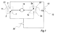
- the accompanying drawing shows a diagram in which a motor 14 is controlled by means of two electromagnetic relays 21 and 22 which, by suitable control, connect the terminals of the motor 14 to the power supply 12 of the system and the negative terminal 30 of the power supply via a suitably controlled FET transistor 30.
- the motor 14 may e.g. be a permanent magnet DC communicator motor.
- the motor will be fed by a power supply, as will be described below, i.e. a power consuming mode, and, immediately after an interruption in the system described, the motor will operate as a generator when there is inertia in the motor or the mechanical system connected to the motor, i.e. a power generating mode. It should be noted that the motor thus generates power on the contact assembly of the relays 21 and 22, notwithstanding that the power supply is disconnected by means of additional coupled switches.
- Each relay comprises a mechanical contact arm which is movable between two contact positions 2, 3 and 2a, 3a, respectively, under control. It also appears from the drawing that, according to the example, each relay is activated by a coil 11, 11a which, in its active state, i.e. when electric control current/voltage is applied to the coil, connects the connecting points 1 and la electrically to the connecting points 3 and 3a, respectively. In the non-activated state of the coil, the relay arms return to their off-position, which is exclusively maintained in accordance with the mechanical properties of the relay, such as spring force, inertia, etc.
- the motor 14 As the motor 14, or the complete system in which the motor is coupled, has a certain inertia, the motor will serve as a generator, which will be disposed more or less directly over the contact points of the relays, for a short or long period after an interruption of the motor.
- These relatively great, and not always predictable voltages will thus be coupled across the contacts in the relays 21, 22, while these are retained or switched under electric control to the positions 3, 3a, and the contact points of the relays will therefore not give rise to bounce and not give rise to substantial destructive sparking in the contact points of the relay.
- the control will deactivate both relays 21, 22 by the spring force of the relay on the relay arm, without the contact points being affected by major electric discharges by these switchings, as the energy of the motor 14 and of the system has been reduced or has disappeared at this time because of a full or partial braking of the system.
- a given delay e.g. 50 ms
- the control will deactivate both relays 21, 22 by the spring force of the relay on the relay arm, without the contact points being affected by major electric discharges by these switchings, as the energy of the motor 14 and of the system has been reduced or has disappeared at this time because of a full or partial braking of the system.
- the FET transistor 30 is interrupted simultaneously with or immediately before the above-mentioned interruption of the motor 14.
- This supplementary interruption of the system by means of the FET transistor 30 ensures that uncertainty with respect to the temporal control of the relays 21, 22 does not suddenly cause the motor 14 to be connected to power. This might occur e.g. if one relay 21, when returning to the non-activated state, is connected to the negative terminal 13 of the power supply before the other relay 22 has switched from its activated state as a consequence of e.g. relay welding.
- a further possibility of adapting or improving the above-mentioned control for concrete applications is to make a so-called soft stop.
- This soft stop is performed by initially allowing the motor 14 to slacken its speed with interrupted FET transistor for e.g. 250 ms before the state of the relay is changed to motor braking, i.e. before the other relay 21 is switched to its activated state.
- the FET transistor 30 is interrupted before or simultaneously with the above-mentioned interruption of the motor 14. It should be remembered in this connection that the response time of the relays is much longer than that of the FET which is interrupted immediately.
- the embodiment shown is particularly advantageous in connection with battery applications, as the system is interrupted and connected to the negative terminal of the power supply in its unenergized state, i.e. with deactivated relays.
- the shown preferred embodiment of the invention provides an improvement of the average service life of the relays incorporated in the motor relays of more than a factor of 100 relatively to the number of achievable switchings.
Landscapes
- Engineering & Computer Science (AREA)
- Power Engineering (AREA)
- Relay Circuits (AREA)
- Control Of Direct Current Motors (AREA)
- Motor And Converter Starters (AREA)
- Stopping Of Electric Motors (AREA)
Applications Claiming Priority (2)
| Application Number | Priority Date | Filing Date | Title |
|---|---|---|---|
| DK26798 | 1998-02-27 | ||
| DK199800267A DK175056B1 (da) | 1998-02-27 | 1998-02-27 | Styring til elmotorer, navnlig i lineære aktuatorer |
Publications (2)
| Publication Number | Publication Date |
|---|---|
| EP0945976A2 true EP0945976A2 (de) | 1999-09-29 |
| EP0945976A3 EP0945976A3 (de) | 2001-02-21 |
Family
ID=8091617
Family Applications (1)
| Application Number | Title | Priority Date | Filing Date |
|---|---|---|---|
| EP99610013A Withdrawn EP0945976A3 (de) | 1998-02-27 | 1999-02-25 | Elektrischer Schaltkreis |
Country Status (4)
| Country | Link |
|---|---|
| US (1) | US6487062B1 (de) |
| EP (1) | EP0945976A3 (de) |
| JP (1) | JPH11289785A (de) |
| DK (1) | DK175056B1 (de) |
Cited By (7)
| Publication number | Priority date | Publication date | Assignee | Title |
|---|---|---|---|---|
| EP1079511A1 (de) * | 1999-08-26 | 2001-02-28 | Linak A/S | Stromversorgung für Gleichstrommotoren |
| DE10108946A1 (de) * | 2001-02-23 | 2002-05-23 | Conti Temic Microelectronic | Verfahren zur Steuerung eines Elektromotors |
| FR2860338A1 (fr) * | 2003-09-30 | 2005-04-01 | Arvinmeritor Light Vehicle Sys | Relais pour appareil electrique en courant continu |
| WO2006048023A1 (en) * | 2004-11-05 | 2006-05-11 | Labofa Munch A/S | A drive mechanism for elevating and lowering a tabletop |
| EP1679785A3 (de) * | 2005-01-06 | 2014-03-19 | LG Electronics, Inc. | Motorsteuervorrichtung |
| CN108116362A (zh) * | 2016-11-28 | 2018-06-05 | 株式会社有信 | 电动转向锁定装置 |
| SE2050582A1 (en) * | 2020-05-19 | 2021-11-20 | Scania Cv Ab | A method for controlling an electrical circuit controlling a direct current motor and such an electrical circuit |
Families Citing this family (5)
| Publication number | Priority date | Publication date | Assignee | Title |
|---|---|---|---|---|
| DE102004008394A1 (de) * | 2004-02-20 | 2005-09-08 | Siemens Ag | Vorrichtung und Verfahren zur Ansteuerung eines im Querzweig einer Brückenschaltung angeordneten Elektromotors |
| WO2006063303A1 (en) * | 2004-12-09 | 2006-06-15 | Won-Door Corporation | Method and apparatus for motor control using relays |
| DE102005016278A1 (de) * | 2005-04-08 | 2006-10-12 | Siemens Ag | Vorrichtung zum Steuern eines elektromechanischen Energiewandlers, insbesondere eines Elektromotors und/oder -generators |
| DE102005041620A1 (de) * | 2005-09-01 | 2007-03-08 | Hiwin Mikrosystem Corp. | Steuergerät für eine induktive Belastung |
| US8115427B2 (en) | 2008-10-23 | 2012-02-14 | Won-Door Corporation | Methods, systems, and devices for a motor control system |
Family Cites Families (7)
| Publication number | Priority date | Publication date | Assignee | Title |
|---|---|---|---|---|
| DE2263039A1 (de) * | 1972-12-22 | 1974-07-04 | Linde Ag | Schaltung fuer einen gleichstrom-motor mit zeitverzoegerungsschalter |
| DE3305770A1 (de) * | 1983-02-19 | 1984-08-23 | Robert Bosch Gmbh, 7000 Stuttgart | Schaltungsanordnung zum ein- und ausschalten eines elektromotorischen antriebes |
| DE3516985A1 (de) | 1985-05-10 | 1986-08-14 | Audi AG, 8070 Ingolstadt | Gleichstrommotor |
| DE3811799A1 (de) | 1988-04-08 | 1989-10-19 | Siemens Ag | Schaltungsanordnung zum bidirektionalen ansteuern von gleichstrommotoren oder gleichstromstellgliedern |
| EP0522492B1 (de) * | 1991-07-10 | 1997-02-05 | Koyo Seiko Co., Ltd. | Lenkung mit elektrischer Hilfskraft |
| JPH0530767A (ja) * | 1991-07-17 | 1993-02-05 | Asmo Co Ltd | 自動停止制御装置 |
| JP2594573Y2 (ja) * | 1993-11-02 | 1999-04-26 | 住友電装株式会社 | リレーの異常検知装置 |
-
1998
- 1998-02-27 DK DK199800267A patent/DK175056B1/da not_active IP Right Cessation
-
1999
- 1999-02-24 US US09/256,111 patent/US6487062B1/en not_active Expired - Lifetime
- 1999-02-25 EP EP99610013A patent/EP0945976A3/de not_active Withdrawn
- 1999-03-01 JP JP11053155A patent/JPH11289785A/ja active Pending
Cited By (9)
| Publication number | Priority date | Publication date | Assignee | Title |
|---|---|---|---|---|
| EP1079511A1 (de) * | 1999-08-26 | 2001-02-28 | Linak A/S | Stromversorgung für Gleichstrommotoren |
| US6509705B2 (en) | 1999-08-26 | 2003-01-21 | Linak A/S | Power supply for DC motors |
| DE10108946A1 (de) * | 2001-02-23 | 2002-05-23 | Conti Temic Microelectronic | Verfahren zur Steuerung eines Elektromotors |
| FR2860338A1 (fr) * | 2003-09-30 | 2005-04-01 | Arvinmeritor Light Vehicle Sys | Relais pour appareil electrique en courant continu |
| WO2006048023A1 (en) * | 2004-11-05 | 2006-05-11 | Labofa Munch A/S | A drive mechanism for elevating and lowering a tabletop |
| EP1679785A3 (de) * | 2005-01-06 | 2014-03-19 | LG Electronics, Inc. | Motorsteuervorrichtung |
| CN108116362A (zh) * | 2016-11-28 | 2018-06-05 | 株式会社有信 | 电动转向锁定装置 |
| SE2050582A1 (en) * | 2020-05-19 | 2021-11-20 | Scania Cv Ab | A method for controlling an electrical circuit controlling a direct current motor and such an electrical circuit |
| SE544138C2 (en) * | 2020-05-19 | 2022-01-11 | Scania Cv Ab | A method for controlling an electrical circuit controlling a direct current motor and such an electrical circuit |
Also Published As
| Publication number | Publication date |
|---|---|
| US6487062B1 (en) | 2002-11-26 |
| DK175056B1 (da) | 2004-05-10 |
| DK26798A (da) | 1999-08-28 |
| EP0945976A3 (de) | 2001-02-21 |
| JPH11289785A (ja) | 1999-10-19 |
Similar Documents
| Publication | Publication Date | Title |
|---|---|---|
| US6487062B1 (en) | Relay circuit for controlling an inductive load | |
| EP3443629B1 (de) | Parallelisierung mechanischer relais zur erhöhten stromführungs- und -umschaltungskapazität | |
| KR100753736B1 (ko) | 차량용 시동기의 전기 모터의 전원 공급을 제어하는 장치 및 차량용 시동기 | |
| CN101080791A (zh) | 使开关设备安全工作的方法和装置 | |
| CN108885952B (zh) | 用于传导和切断电流的开关设备 | |
| EP1605458A3 (de) | Motor insbesondere für Plattenlaufwerk | |
| WO2001054262A9 (en) | Railway switch machine motor control apparatus | |
| EP0576257A2 (de) | Geschwindigkeitsregelvorrichtung für einen Gleichstrommotor | |
| WO1998038728A1 (en) | Motor reversing circuit | |
| CN109478476B (zh) | 用于中压断路器的致动器 | |
| US20040066159A1 (en) | DC motor having a braking circuit | |
| KR20160140293A (ko) | 저전력 릴레이 구동 장치 | |
| JP7517968B2 (ja) | 制御装置 | |
| JP2922294B2 (ja) | フライバック電流減衰装置 | |
| US4158158A (en) | D.C. controller for battery powered electric motor | |
| US20230318513A1 (en) | Control electronics, electromechanical actuator, aircraft and method for damping the movement of an electromechanical actuator | |
| JP7323878B1 (ja) | 電流開閉装置 | |
| KR101273980B1 (ko) | 전기기계 전력 컨버터를 제어하기 위한 장치 및 방법 | |
| US11342148B2 (en) | Relay device and control method of relay device | |
| JP3608483B2 (ja) | 有極性コンデンサの保護装置 | |
| JPH04354374A (ja) | ハイブリッドスイッチ | |
| US20070145937A1 (en) | Braking system for electric step motors | |
| KR0138035Y1 (ko) | 모터 과부하 방지회로 | |
| CN215105647U (zh) | 风扇反转控制装置、包括该装置的液压系统和作业机械 | |
| KR100285028B1 (ko) | 핸들 부착타입의 휠 방향 작동 제어장치 |
Legal Events
| Date | Code | Title | Description |
|---|---|---|---|
| PUAI | Public reference made under article 153(3) epc to a published international application that has entered the european phase |
Free format text: ORIGINAL CODE: 0009012 |
|
| AK | Designated contracting states |
Kind code of ref document: A2 Designated state(s): CH DE DK ES FR GB IT LI NL SE |
|
| AX | Request for extension of the european patent |
Free format text: AL;LT;LV;MK;RO;SI |
|
| PUAL | Search report despatched |
Free format text: ORIGINAL CODE: 0009013 |
|
| AK | Designated contracting states |
Kind code of ref document: A3 Designated state(s): AT BE CH CY DE DK ES FI FR GB GR IE IT LI LU MC NL PT SE |
|
| AX | Request for extension of the european patent |
Free format text: AL;LT;LV;MK;RO;SI |
|
| 17P | Request for examination filed |
Effective date: 20010820 |
|
| AKX | Designation fees paid |
Free format text: CH DE DK ES FR GB IT LI NL SE |
|
| 17Q | First examination report despatched |
Effective date: 20071015 |
|
| APBK | Appeal reference recorded |
Free format text: ORIGINAL CODE: EPIDOSNREFNE |
|
| APBN | Date of receipt of notice of appeal recorded |
Free format text: ORIGINAL CODE: EPIDOSNNOA2E |
|
| APBR | Date of receipt of statement of grounds of appeal recorded |
Free format text: ORIGINAL CODE: EPIDOSNNOA3E |
|
| APAF | Appeal reference modified |
Free format text: ORIGINAL CODE: EPIDOSCREFNE |
|
| APBT | Appeal procedure closed |
Free format text: ORIGINAL CODE: EPIDOSNNOA9E |
|
| STAA | Information on the status of an ep patent application or granted ep patent |
Free format text: STATUS: THE APPLICATION IS DEEMED TO BE WITHDRAWN |
|
| 18D | Application deemed to be withdrawn |
Effective date: 20130903 |