EP0946077A2 - Optische Vermittlungseinrichtung mit Wellenlängenmultiplex-Technik - Google Patents
Optische Vermittlungseinrichtung mit Wellenlängenmultiplex-Technik Download PDFInfo
- Publication number
- EP0946077A2 EP0946077A2 EP99105133A EP99105133A EP0946077A2 EP 0946077 A2 EP0946077 A2 EP 0946077A2 EP 99105133 A EP99105133 A EP 99105133A EP 99105133 A EP99105133 A EP 99105133A EP 0946077 A2 EP0946077 A2 EP 0946077A2
- Authority
- EP
- European Patent Office
- Prior art keywords
- wavelength
- optical signals
- optical
- wdm optical
- zeroth
- Prior art date
- Legal status (The legal status is an assumption and is not a legal conclusion. Google has not performed a legal analysis and makes no representation as to the accuracy of the status listed.)
- Withdrawn
Links
- 230000003287 optical effect Effects 0.000 title claims abstract description 660
- 238000005516 engineering process Methods 0.000 title description 4
- 238000000034 method Methods 0.000 claims abstract description 22
- 238000006243 chemical reaction Methods 0.000 claims description 4
- 238000005457 optimization Methods 0.000 abstract 1
- 239000004065 semiconductor Substances 0.000 description 20
- 239000013307 optical fiber Substances 0.000 description 9
- 239000000758 substrate Substances 0.000 description 9
- VYPSYNLAJGMNEJ-UHFFFAOYSA-N Silicium dioxide Chemical compound O=[Si]=O VYPSYNLAJGMNEJ-UHFFFAOYSA-N 0.000 description 6
- XUIMIQQOPSSXEZ-UHFFFAOYSA-N Silicon Chemical compound [Si] XUIMIQQOPSSXEZ-UHFFFAOYSA-N 0.000 description 5
- 229910052710 silicon Inorganic materials 0.000 description 5
- 239000010703 silicon Substances 0.000 description 5
- 230000000694 effects Effects 0.000 description 4
- 230000005540 biological transmission Effects 0.000 description 3
- 229920006395 saturated elastomer Polymers 0.000 description 3
- 239000000377 silicon dioxide Substances 0.000 description 3
- 238000010586 diagram Methods 0.000 description 2
- 239000004973 liquid crystal related substance Substances 0.000 description 2
- GQYHUHYESMUTHG-UHFFFAOYSA-N lithium niobate Chemical compound [Li+].[O-][Nb](=O)=O GQYHUHYESMUTHG-UHFFFAOYSA-N 0.000 description 2
- 239000011159 matrix material Substances 0.000 description 2
- 238000010521 absorption reaction Methods 0.000 description 1
- 238000004891 communication Methods 0.000 description 1
- 239000000835 fiber Substances 0.000 description 1
- 230000010287 polarization Effects 0.000 description 1
- 230000003595 spectral effect Effects 0.000 description 1
- PBCFLUZVCVVTBY-UHFFFAOYSA-N tantalum pentoxide Inorganic materials O=[Ta](=O)O[Ta](=O)=O PBCFLUZVCVVTBY-UHFFFAOYSA-N 0.000 description 1
- 238000002834 transmittance Methods 0.000 description 1
Images


Classifications
-
- H—ELECTRICITY
- H04—ELECTRIC COMMUNICATION TECHNIQUE
- H04Q—SELECTING
- H04Q11/00—Selecting arrangements for multiplex systems
- H04Q11/0001—Selecting arrangements for multiplex systems using optical switching
- H04Q11/0005—Switch and router aspects
-
- H—ELECTRICITY
- H04—ELECTRIC COMMUNICATION TECHNIQUE
- H04Q—SELECTING
- H04Q11/00—Selecting arrangements for multiplex systems
- H04Q11/0001—Selecting arrangements for multiplex systems using optical switching
- H04Q11/0005—Switch and router aspects
- H04Q2011/0007—Construction
- H04Q2011/0009—Construction using wavelength filters
-
- H—ELECTRICITY
- H04—ELECTRIC COMMUNICATION TECHNIQUE
- H04Q—SELECTING
- H04Q11/00—Selecting arrangements for multiplex systems
- H04Q11/0001—Selecting arrangements for multiplex systems using optical switching
- H04Q11/0005—Switch and router aspects
- H04Q2011/0007—Construction
- H04Q2011/0011—Construction using wavelength conversion
-
- H—ELECTRICITY
- H04—ELECTRIC COMMUNICATION TECHNIQUE
- H04Q—SELECTING
- H04Q11/00—Selecting arrangements for multiplex systems
- H04Q11/0001—Selecting arrangements for multiplex systems using optical switching
- H04Q11/0005—Switch and router aspects
- H04Q2011/0007—Construction
- H04Q2011/0013—Construction using gating amplifiers
-
- H—ELECTRICITY
- H04—ELECTRIC COMMUNICATION TECHNIQUE
- H04Q—SELECTING
- H04Q11/00—Selecting arrangements for multiplex systems
- H04Q11/0001—Selecting arrangements for multiplex systems using optical switching
- H04Q11/0005—Switch and router aspects
- H04Q2011/0007—Construction
- H04Q2011/0016—Construction using wavelength multiplexing or demultiplexing
-
- H—ELECTRICITY
- H04—ELECTRIC COMMUNICATION TECHNIQUE
- H04Q—SELECTING
- H04Q11/00—Selecting arrangements for multiplex systems
- H04Q11/0001—Selecting arrangements for multiplex systems using optical switching
- H04Q11/0005—Switch and router aspects
- H04Q2011/0052—Interconnection of switches
- H04Q2011/0058—Crossbar; Matrix
-
- H—ELECTRICITY
- H04—ELECTRIC COMMUNICATION TECHNIQUE
- H04Q—SELECTING
- H04Q11/00—Selecting arrangements for multiplex systems
- H04Q11/0001—Selecting arrangements for multiplex systems using optical switching
- H04Q11/0062—Network aspects
- H04Q2011/0075—Wavelength grouping or hierarchical aspects
Definitions
- This invention relates to an optical switching apparatus applied wavelength division multiplexing techniques thereto.
- optical switching apparatus switches optical signals without converting them into electrical signals. Recently, such optical switching apparatus might be expected to realize switching with a large amount of capacity which can not be realized by an electrical switching apparatus.
- optical space switching or an optical space-division switching
- optical wavelength switching or an optical wavelength-division switching
- optical time switching or an optical time-division switching
- combinations thereof such as an optical wavelength/space switching (an optical wavelength-division/ space-division switching) and an optical wavelength/time switching (an optical wavelength-division/time-division switching).
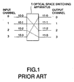
- Fig. 1 shows an example of an optical space switching apparatus.
- zeroth through third input channels are assigned to zeroth through third input ports 10-0 through 10-3, respectively.
- zeroth through third output channels are assigned to zeroth through third output ports 11-0 through 11-3, respectively.
- Such optical space switching apparatus 1 can connect between any input channel and any output channel.
- the optical space switching apparatus which the present invention relates, comprises an existing optical space switch of splitter/combiner type where semiconductor laser amplifiers are used as optical gate switches.
- an existing optical space switch of splitter/combiner type where semiconductor laser amplifiers are used as optical gate switches.
- such switch is disclosed in Yoshiharu Maeno et al "The Possibility of Optical Switching Technology for Parallel Processing Systems", IEICE, SB-9-5, 1996.
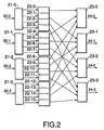
- Fig. 2 illustrates an optical switch of splitter/ combiner type known to the inventors.
- the illustrated optical space switch comprises zeroth through third input waveguides 20-0 through 20-3, zeroth through third beam splitters 21-0 through 21-3, zeroth through fifteenth optical gate switches 22-0 through 22-15, zeroth through third beam combiners 23-0 through 23-3, and zeroth through third output waveguides 24-0 through 24-3.
- One kind of the existing optical gate switches is a semiconductor laser amplifier, which is turned into a light-transmitting or an on state and a light absorbing or an off state when an electric current is fed thereto and is not fed thereto, respectively.
- the zeroth optical gate switch 22-0 turned into the on state, the zeroth input waveguide 20-0 is connected to the zeroth output waveguide 24-0.
- the splitter/combiner type optical switch is strictly nonblocking and serves as a so-called crossbar switch where every pairs of input and output ports have dedicated connection paths. And accordingly, the optical space switching apparatus comprising the above switch also serves as a crossbar network.
- the optical switch of splitter/combiner type requires optical gate switches, (the number of ports) 2 in number, and therefore, has a fault that it is difficult to be implemented, as the number of ports becomes large.
- Fig. 3 shows another optical space switching apparatus known to the inventors.
- the apparatus is applied a wavelength division multiplexing (WDM) technology thereto, and achieves to reduce the number of the optical gate switches as compared with the apparatus illustrated in Fig. 2.
- WDM wavelength division multiplexing
- this apparatus zeroth through fifteenth input optical signal each having any one of zeroth through third wavelengths ⁇ 0 through ⁇ 3 are supplied from zeroth through fifteenth input ports 10-0 through 10-15 and combined by zeroth through third beam combiners 31-0 through 31-3.
- the zeroth beam combiner 31-0 when the zeroth through third input optical signals having zeroth through third wavelengths ⁇ 0 through ⁇ 3 are input to the zeroth beam combiner 31-0 from the zeroth through third input ports, the zeroth beam combiner 31-0 combines the zeroth through third input optical signals to produce a zeroth WDM optical signal.
- the first beam combiner 31-1 combines the fourth through seventh input optical signals having zeroth through third wavelengths ⁇ 0 through ⁇ 3 to produce a first WDM optical signal.
- the second beam combiner 31-2 are input the eighth through eleventh input optical signals having zeroth thereto from third wavelengths ⁇ 0 through ⁇ 3 from the eighth through eleventh input ports, and then, combines the eighth through eleventh input optical signals to produce a second WDM optical signal.
- the third beam combiner 31-3 combines the twelfth through fifteenth input optical signals having zeroth through third wavelengths ⁇ 0 through ⁇ 3 to produce a third WDM optical signal.
- the optical space switch 32 illustrated in Fig. 3 is of a 4 x 16 crossbar switch adapted to perform 1-to-4 multicasting at maximum.
- the illustrated switch 32 has zeroth through third input ports i0 through i3 to which the zeroth through third WDM optical signals are supplied and zeroth through fifteenth output ports o0 through o15 from which zeroth through fifteenth switched WDM optical signals are outputted.
- the zeroth through fifteenth output ports of the optical space switch 32 are connected to zeroth through fifteenth wavelength selectors 33A-0 through 33A-15, respectively.
- the zeroth through fifteenth wavelength selectors 33A-0 through 33A-15 select the optical signal of the desired wavelengths from the zeroth through fifteenth switched WDM optical signals outputted from the optical space switch 32 and produce zeroth through fifteenth selected optical signals.
- the zeroth through fifteenth wavelength selectors 33A-0 through 33A-15 are connected to zeroth through fifteenth output ports 11-0 through 11-15, respectively.
- the zeroth through fifteenth output ports 11-0 through 11-15 transmit the zeroth through fifteenth selected optical signals as zeroth through fifteenth output optical signals, respectively.
- the optical space switching apparatus has a function of a 16 x 16 crossbar network.
- the optical space switch 32 may be of splitter/combiner type described above, and may include sixty-four optical gate switches.
- each of the existing wavelength selectors 33A (suffixes omitted) comprises optical gate switches, the number of which is equal to the number of wavelengths transmitted into each selector.
- the number of wavelengths multiplexed into the switched WDM optical signal is equal to four, and therefore, the number of optical gate switches is also equal to four.
- a wavelength demultiplexer demultiplexes switched WDM optical signal into individual optical signals with different wavelengths and transmits the individual optical signals into the optical gate switches, respectively. And then, one of the gate switches corresponding to desired wavelength turns on while the others turn off so that only the optical signal with desired wavelength is outputted from the selector.
- the optical switching apparatus of space division type illustrated in Fig. 3 has 128 optical gate switches in total.
- another 16 x 16 apparatus consisting of a splitter/combiner type optical switch requires 256 optical gate switches.
- the number of optical gate switches which comprise the apparatus illustrated in Fig. 3 is reduced to 1/2 as compared with another apparatus consisting splitter/ combiner type optical switch.
- Fig. 4 shows another example of an optical wavelength/space switching apparatus.
- zeroth through third input channels are assigned to zeroth and first input ports 10-0 and 10-1 and zeroth and first wavelengths ⁇ 0 and ⁇ 1 of optical signals transmitting on each of input ports.
- zeroth through third output channels are assigned to zeroth and first output ports 11-0 and 11-1 and zeroth and first wavelengths ⁇ 0 and ⁇ 1 of optical signals transmitting on each of output ports.
- Such optical wavelength/space switching apparatus 2 can connect between any input channel and any output channel.
- an optical wavelength/space switching apparatus having small sized-hardware is disclosed in Japanese Unexamined Patent Publication No. Hei 3-219793, namely, JP-A 3-219793 and is incorporated herein by reference.
- optical space switching apparatus illustrated in Fig. 3.
- the optical wavelength/space switching apparatus known to the inventors has no beam combiners 31-0 through 31-3 as preliminarily processing of the optical space switch 32 and directly are input WDM optical signals to the input ports of the optical space switch through the input ports.
- the optical wavelength/space switching apparatus has, as latter stage of the wavelength selectors, wavelength converters corresponding to the wavelength selectors 33A-0 through 33A-15 and beam combiners.
- the present invention provides optical switching apparatuses improved in various aspects, such as the size of hardware and the performance thereof.
- the numbers of WDM optical signals and wavelengths depend on an environment to which the optical switching apparatus is adapted. And furthermore, it is getting things backwards to modify the environment which has already been defined into another environment which corresponds to the numbers of WDM optical signals and wavelength transmitted into the optical space switch. Thus, the numbers are restricted by the environment.
- the present invention provides the following method of delivering a plurality of WDM optical signals to a plurality of input ports of an optical space switch.
- the method comprises preliminarily processing the WDM optical signals in relation to the number of input ports of the optical space switch, by optically processing the WDM optical signals so that the number of processed WDM optical signals responding to the input ports and the processed number of wavelengths of each processed WDM optical signal is equal to each other.
- the numbers of the input ports, the processed number of wavelength, the WDM optical signals, the wavelengths multiplexed in each of the WDM optical signals are equal to K, J, N, and M, respectively, where K, J, N, and M are integers not less than two.
- the above method may comprise using the optical space switch which further has K*M*N optical gate switches and which is connected to M*N wavelength selectors each comprising M*N/K additional optical gate switches, after the preliminarily processing.
- the above method may comprise preliminarily processing the WDM optical signals in relation to the number of input ports of the optical space switch, by optically processing the WDM optical signals so that M*N is equal to J*K.
- the present invention further provides an optical switching apparatus which comprises an optical converter, an optical space switch, and wavelength selectors, as the followings. Responsive to N WDM optical signals each of which has M multiplexed wavelengths, the optical converter converts the N WDM optical signals into K input WDM optical signals each of which has J multiplexed wavelengths, wherein all of N, M, K and J are integers not less than two and J*K is equal to M*N.
- the optical space switch comprises K input ports and M*N output ports. The optical space switch responds to K input WDM optical signals to produce M*N switched WDM optical signals through the M*N output ports.
- the wavelength selectors is M*N. Responsive to the M*N switched WDM optical signals, respectively, the wavelength selectors selects one of J wavelengths multiplexed into the responding switched WDM optical signal.
- Zeroth through seventh input optical signals having zeroth through seventh wavelengths ⁇ 0 through ⁇ 7 are supplied from zeroth through seventh input ports 10-0 through 10-7, respectively, and combined (or multiplexed) by a zeroth beam combiner (or optical multiplexer) 31-0 into a WDM optical signal to be supplied to a zeroth input port i0 of a wavelength router 6.
- eighth through fifteenth input optical signals having zeroth through seventh wavelengths ⁇ 0 through ⁇ 7 are supplied from eighth through fifteenth input ports 10-8 through 10-15, respectively, and combined by a first beam combiner 31-1 into a WDM optical signal to be supplied to a first input port i1 of the wavelength router 6.
- the wavelength router 6 may be implemented by an silica arrayed-waveguide grating formed on a silicon substrate.
- silica arrayed-waveguide grating formed on a silicon substrate.
- such router is disclosed in Hiroshi Takahashi et al "Wavelength Multiplexer Based on SiO 2 -Ta 2 O 5 Arrayed-Waveguide Grating", Journal of Lightwave Technology, Vol. 12, No. 6, June 1994.
- transmission characteristics of the wavelength router 6 are illustrated as the relationship between the wavelengths of the optical signals and the transmittance.
- the optical signals have a wavelength channel spacing of 0.8nm.
- the wavelength router 6 has a wavelength channel spacing and a free spectral range (FSR) equal to 0.8nm and 3.2nm, respectively.
- FSR free spectral range
- the optical signals having the zeroth and the fourth wavelengths ⁇ 0 and ⁇ 4 are transmitted from the zeroth input port i0 to a zeroth output o0.
- the optical signals having the first and the fifth wavelengths ⁇ 1 and ⁇ 5 are transmitted from the zeroth input port i0 to a first output port o1.
- the optical signals having the second and the sixth wavelengths ⁇ 2 and ⁇ 6 are transmitted.
- the optical signals having the third and the seventh wavelengths ⁇ 3 and ⁇ 7 are transmitted.
- a WDM optical signal including the zeroth through the seventh wavelengths ⁇ 0 through ⁇ 7 is supplied through each of the zeroth and the first input ports i0 and i1
- a WDM optical signal including the zeroth, the second, the fourth, and the sixth wavelengths ⁇ 0, ⁇ 2, ⁇ 4, and ⁇ 6 (hereinafter referred to as a wavelength group A) is produced from each of the zeroth and the second output ports o0 and o2.
- another WDM optical signal including the first, the third, the fifth, and the seventh wavelengths ⁇ 1, ⁇ 3, ⁇ 5, and ⁇ 7 (hereinafter referred to as a wavelength group B) is produced from each of the first and the third output ports o1 and o3.
- the WDM optical signals having the wavelength groups A and B are delivered from the wavelength router 6 to an optical space switch (or an optical space division switch) 32.
- the optical space switch 32 of this embodiment is a 4 x 16 optical crossbar switch adapted to perform 1-to-16 multicasting at maximum, and has zeroth through third input ports i0 through i3 and zeroth through fifteenth output ports o0 through o15.
- the optical space switch 32 directs the WDM optical signal supplied through each input port to a desired output port.
- arbitration control is carried out so that those WDM optical signals supplied through different input ports are not outputted from a common output port.
- the optical space switch 32 is of splitter/combiner type illustrated in Fig. 7 and comprises zeroth through third input waveguides 20-0 through 20-3, zeroth through third beam splitters 21-0 through 21-3, zeroth through fifteenth beam combiners 23-0 through 23-15, and zeroth through fifteenth output waveguides 24-0 through 24-15, zeroth through sixty-third optical gate switches or semiconductor laser amplifiers 22-0 through 22-63.
- the input waveguides, beam splitters, beam combiners, and output waveguides are all formed on a common silicon substrate while the optical gate switches are mounted on the substrate.
- Each of the optical gate switches 22 (suffixes omitted) is turned into a light-transmitting or an on state and a light-absorbing or an off state when an electric current is supplied and is not supplied, respectively.
- a crossbar switch function is achieved.
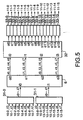
- Zeroth through fifteenth switched WDM optical signals produced from the optical space switch 32 are supplied to zeroth through fifteenth wavelength selectors 33-0 through 33-15, respectively, as illustrated in Fig. 5.
- each of the wavelength selectors 33 (suffixes omitted) comprises an input waveguide 40, a wavelength demultiplexer 41 of an arrayed-waveguide grating type, a beam combiner 43, an output waveguide 44, and zeroth through third optical gate switches 42-0 through 42-3 as semiconductor laser amplifiers.
- the input waveguide, wavelength demultiplexer, beam combiner, and output waveguide are all formed on a common silicon substrate while the optical gate switches are mounted on the substrate.
- Each wavelength selector 33 serves as a 4 x 1 wavelength selector for selecting and outputting a desired one of four wavelengths.
- the switched WDM optical signal having the zeroth, the second, the fourth, and the sixth wavelengths (or the first, the third, the fifth, and the seventh wavelengths) ⁇ 0, ⁇ 2, ⁇ 4, and ⁇ 6 (or ⁇ 1, ⁇ 3, ⁇ 5, and ⁇ 7) is supplied to an input port i0 of the wavelength demultiplexer 41.
- the wavelength demultiplexer 41 demultiplexes the switched WDM optical signal into individual wavelengths to produce an optical signal having the zeroth (or the first) wavelength ⁇ 0 (or ⁇ 1) through a zeroth output port o0, an optical signal having the second (or the third) wavelength ⁇ 2 (or ⁇ 3) through a first output port o1, an optical signal having the fourth (or the fifth) wavelength ⁇ 4 (or ⁇ 5) through a second output port o2, and an optical signal having the sixth (or the seventh) wavelength ⁇ 6 (or ⁇ 7) through a third output port o3.
- the optical space switch 32 carries out arbitration control so that the WDM optical signals having the wavelength groups A and B are not simultaneously supplied to any single wavelength selector 33.
- one of the wavelength groups A and B is supplied through the input port i0 and each of the four output ports produces an optical signal of a single wavelength to be delivered to a corresponding one of the optical gate switches 42 (suffixes omitted).
- One of the optical gate switches 42 (suffixes omitted) which is supplied with a desired wavelength is turned on while the others are turned off.
- the optical signal of the desired wavelength is selected from the four wavelengths and passes through the beam combiner 43 to be delivered through the output waveguide 44.
- Zeroth through fifteenth selected optical signals produced from the zeroth through the fifteenth wavelength selectors 33-0 through 33-15 are delivered to zeroth through fifteenth output ports 11-0 through 11-15, respectively, as illustrated in Fig. 5.
- the optical switching apparatus of space division type has a function of 16 x 16 crossbar network.
- connection between the zeroth input port 10-0 and the zeroth output port 11-0 and connection between the tenth input port 10-10 and the first output port 11-1 are simultaneously carried out.
- the optical signal having the zeroth wavelength ⁇ 0 and supplied from the zeroth input port 10-0 passes through the beam combiner 31-0 and then through the wavelength router 6 (from the zeroth input port i0 to the zeroth output port o0) to be supplied to the zeroth input port i0 of the optical space switch 32.
- the optical signal of the second wavelength ⁇ 2 supplied from the tenth input port 10-10 passes through the beam combiner 31-1 and then through the wavelength router 6 (from the first input port i1 to the zeroth output port o0) to be supplied to the zeroth input port i0 of the optical space switch 32.
- the optical space switch 32 multicasts to the zeroth and the first output ports o0 and o1 the WDM optical signal having the zeroth and the second wavelengths ⁇ 0 and ⁇ 2 supplied from the zeroth input port i0.
- the zeroth wavelength selector 33-0 selects the zeroth wavelength ⁇ 0 for delivery to the zeroth output port 11-0.
- the first wavelength selector 33-1 selects the second wavelength ⁇ 2 for delivery to the first output port 11-1.
- the wavelength router 6 serves as an optical converter to reduce the number of multiplexed wavelengths. Specifically, at the input of the wavelength router 6, the number of multiplexed wavelengths is equal to 8 while the number of multiplexed spaces is equal to 2. Since the WDM optical signals of the wavelength group A produced from the zeroth and the second output ports o0 and o2 of the wavelength router 6 are different in wavelength from the WDM optical signals of the wavelength group B produced from the first and the third output ports o1 and o3, the number of wavelengths used in the whole apparatus is equal to 8 in total. However, the number of multiplexed wavelengths on a single route is equal to 4 at maximum and the wavelength selectors 33 (suffixes omitted) similarly operate for both of the wavelength groups. Therefore, the number of multiplexed wavelengths is reduced to 4.
- the number of the optical gate switches required in the apparatus is reduced. If the wavelength router 6 is not provided, the optical space switch 32 is of a 2 x 16 type while the wavelength selectors 33 is of a 8 x 1 type. Therefore, the number of the optical gate switches 22 required in the optical space switch 32 is equal to 32. The number of the optical gate switches 42 required per each wavelength selector 33 is equal to 8. Thus, the optical switching apparatus requires 160 optical gate switches in total. On the other hand, in this embodiment, the optical space switch 32 requires 64 optical gate switches while each wavelength selector 33 requires 4 optical gate switches. Thus, the optical switching apparatus according to this embodiment requires 128 optical gate switches in total. Thus, the number is reduced to 4/5 as compared with the case where the wavelength router 6 is not provided.
- the number of multiplexed wavelengths of the WDM optical signal supplied to the optical gate switch 22 of the optical space switch 32 is reduced so that the optical gate switch 22 as the semiconductor laser amplifier is hardly saturated.
- eight wavelengths are supplied to the optical gate switch 22 at maximum.
- four wavelengths are supplied at maximum.
- a light intensity ( or an optical signal intensity ) for each wavelength can be increased to twice as compared with the case where the wavelength router 6 is not provided. Therefore, a light intensity of the optical signal delivered to the output port 11 (suffixes omitted) is increased to twice also.
- the zeroth through the fifteenth input optical signals are supplied through the zeroth through the fifteenth input ports 10-0 through 10-15, respectively.
- each of the zeroth, the second, the fourth, the sixth, the eighth, the tenth, the twelfth, and the fourteenth input optical signals has the zeroth wavelength ⁇ 0 while each of the first, the third, the fifth, the seventh, the ninth, the eleventh, the thirteenth, and the fifteenth input optical signals has the first wavelength ⁇ 1.
- the zeroth and the first input optical signals are supplied to a zeroth primary-stage beam combiner 31A-0.
- the second and the third input optical signals are supplied to a first primary-stage beam combiner 31A-1.
- the fourth and the fifth input optical signals are supplied to a second primary-stage beam combiner 31A-2.
- the sixth and the seventh input optical signals are supplied to a third primary-stage beam combiner 31A-3.
- the eighth and the ninth input optical signals are supplied to a fourth primary-stage beam combiner 31A-4.
- the tenth and the eleventh input optical signals are supplied to a fifth primary-stage beam combiner 31A-5.
- the twelfth and the thirteenth input optical signals are supplied to a sixth primary-stage beam combiner 31A-6.
- the fourteenth and the fifteenth input optical signals are supplied to a seventh primary-stage beam combiner 31A-7.
- Each of the first through the seventh primary-stage beam combiners 31A-0 through 31A-7 combines two input optical signals supplied thereto to produce a WDM optical signal of two wavelengths.
- the zeroth through the seventh primary-stage beam combiners 31A-0 through 31A-7 produce zeroth through seventh primary-stage WDM optical signals, respectively.
- the first, the third, the fifth, and the seventh primary-stage WDM optical signals are supplied to zeroth through third wavelength shifters 7-0 through 7-3, respectively.
- Each of the zeroth through the third wavelength shifters 7-0 through 7-3 wavelength-shifts the zeroth and the first wavelengths ⁇ 0 and ⁇ 1 of the primary-stage WDM optical signal supplied thereto into a WDM optical signal of the second and the third wavelengths ⁇ 2 and ⁇ 3.
- the zeroth wavelength shifter 7-0 wavelength-shifts the first primary-stage WDM optical signal to produce a zeroth wavelength-shifted WDM optical signal.
- the first wavelength shifter 7-1 wavelength-shifts the third primary-stage WDM optical signal to produce a first wavelength-shifted WDM optical signal.
- the second wavelength shifter 7-2 wavelength shifts the fifth primary-stage WDM optical signal to produce a second wavelength-shifted WDM optical signal.
- the third wavelength shifter 7-3 wavelength-shifts the seventh primary-stage WDM optical signal to produce a third wavelength-shifted WDM optical signal.
- each of the zeroth through the third wavelength shifters 7-0 through 7-3 comprises a wavelength shifter using four-wave-mixing ( FWM ) in the semiconductor laser amplifier (SLA).
- FWM semiconductor laser amplifier
- SLA semiconductor laser amplifier
- the wavelength shifter 7 (suffixes omitted) according to this embodiment comprises an input optical fiber 50, zeroth and first pump light sources 51-0 and 51-1, first and second beam combiners 52 and 53, a semiconductor laser amplifier 54, a wavelength filter 55, and an output optical fiber 56.
- Each of the zeroth and the first pump light sources 51-0 and 51-1 comprises a semiconductor laser.
- the zeroth pump light source 51-0 produces a zeroth pump light having a zeroth pump wavelength ⁇ p0 while the first pump light source 51-1 produces a first pump light having a first pump wavelength ⁇ p1.
- the zeroth and the first pump lights are combined by the first beam combiner 52 to produce a combined pump light having the zeroth and the first pump wavelengths ⁇ p0 and ⁇ p1.
- the combined pump light is supplied to the second beam combiner 53.
- the second beam combiner 53 is also supplied from the input optical fiber 50 with the primary-stage WDM optical signal having the zeroth and the first wavelengths ⁇ 0 and ⁇ 1.
- the second beam combiner 53 is supplied on one hand with the primary-stage WDM optical signal supplied through the input optical fiber 50 and having the zeroth and the first wavelength ⁇ 0 and ⁇ 1 and on the other hand with the combined pump light having the zeroth and the first pump wavelengths ⁇ p0 and ⁇ p1 produced from the zeroth and the first pump light sources 51-0 and 51-1 as semiconductor lasers.
- the second beam combiner 53 combines the primary-stage WDM optical signal and the combined pump light to produce a WDM optical signal having the zeroth and the first wavelengths ⁇ 0 and ⁇ 1 and the zeroth and the first pump wavelengths ⁇ p0 and ⁇ p1.
- the wavelength filter 55 transmits the second and the third wavelengths ⁇ 2 and ⁇ 3 of the WDM optical signal among the six wavelengths ⁇ 0, ⁇ 1, ⁇ 2, ⁇ 3, ⁇ p0, and ⁇ p1 to produce a wavelength-shifted WDM optical signal which is delivered to the output optical fiber 56.
- the zeroth through the third wavelength-shifted WDM optical signals are supplied to zeroth through third secondary-stage beam combiners 8-0 through 8-3, respectively.
- the zeroth through the third secondary-stage beam combiners 8-0 through 8-3 are supplied with the zeroth, the second, the fourth, and the sixth primary-stage WDM optical signals produced by the zeroth, the second, the fourth, and the sixth primary-stage beam combiners 31-0, 31-2, 31-4, and 31-6 and having the zeroth and the first wavelengths ⁇ 0 and ⁇ 1.
- the zeroth secondary-stage beam combiner 8-0 combines the zeroth primary-stage WDM optical signal and the zeroth wavelength-shifted WDM optical signal to produce a zeroth secondary-stage WDM optical signal having the zeroth through the third wavelengths ⁇ 0 through ⁇ 3.
- the first secondary-stage beam combiner 8-1 combines the second primary-stage WDM optical signal and the first wavelength-shifted WDM optical signal to produce a first secondary-Stage WDM optical signal having the zeroth through the third wavelengths ⁇ 0 through ⁇ 3.
- the second secondary-stage beam combiner 8-2 combines the fourth primary-stage WDM optical signal and the second wavelength-shifted WDM optical signal to produce a second secondary-stage WDM optical signal having the zeroth through the third wavelengths ⁇ 0 through ⁇ 3.
- the third secondary-stage beam combiner 8-3 combines the sixth primary-stage WDM optical signal and the third wavelength-shifted WDM optical signal to produce a third secondary-stage WDM optical signal having the zeroth through the third wavelengths ⁇ 0 through ⁇ 3.
- the zeroth through the third secondary-stage WDM optical signals are supplied to the optical space switch 32.
- the optical space switch 32 illustrated in the figure is adapted to perform 1-to-16 multicasting at maximum and has the zeroth through the third input ports i0 through i3 and the zeroth through the fifteenth output ports o0 through o15.
- the optical space switch 32 directs the secondary-stage WDM optical signal supplied through each input port to a desired output port.
- arbitration control is carried out so that those WDM optical signals supplied through different input ports are not outputted from any common output port.
- the optical space switch 32 in this embodiment is similar in structure and operation to that of the first embodiment and will not be described any longer.
- the optical space switch 32 delivers the zeroth through the fifteenth switched WDM optical signals through the zeroth through the fifteenth output ports, respectively.
- the zeroth through the fifteenth switched WDM optical signals produced by the optical space switch 32 are supplied to the zeroth through the fifteenth wavelength selectors 33A-0 through 33A-15, respectively.
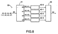
- each of the wavelength selectors 33A (suffixes omitted) comprises the input waveguide 40, a wavelength demultiplexer 41A of an arrayed-waveguide grating type, the beam combiner 43, the output waveguide 44, and the first through the third optical gate switches 42-0 through 42-3 as semiconductor laser amplifiers.
- the input waveguide, wavelength demultiplexer, beam combiners, and output waveguide are all formed on a common silicon substrate while the optical gate switches are mounted on the substrate.
- the wavelength selector 33A serves as a 4 x 1 wavelength selector for selecting and outputting a desired one of four wavelengths.
- a switched WDM optical signal having the zeroth through the third wavelengths ⁇ 0 through ⁇ 3 is supplied from the input waveguide 40 to an input port i0 of the wavelength demultiplexer 41A.
- the wavelength demultiplexer 41A demultiplexes the switched WDM optical signal into individual wavelengths to produce optical signals of the zeroth wavelength ⁇ 0, the first wavelength ⁇ 1, the second wavelength ⁇ 2, and the third wavelength ⁇ 3 through zeroth through third output ports o0 through o3, respectively.
- One of the optical gate switches 42 (suffixes omitted) which is supplied with the desired wavelength is turned on while the others are turned off.
- the optical signal of the desired wavelength is selected from the four wavelengths and sent through the beam combiner 43 to be outputted from the output waveguide 44.
- the zeroth through the fifteenth wavelength selectors 33A-0 through 33A-15 select the optical signals of the desired wavelengths from the zeroth through the fifteenth switched WDM optical signals and produce zeroth through fifteenth selected optical signals.
- the zeroth through the fifteenth selected optical signals produced by the zeroth through the fifteenth wavelength selectors 33A-0 through 33A-15 are delivered to zeroth through fifteenth output ports 11-0 through 11-15, respectively.
- the optical switching apparatus of space division type has a function of a 16 x 16 crossbar network.
- connection between the zeroth input port 10-0 and the zeroth output port 11-0 and connection between the second input port 10-2 and the first output port 11-1 are simultaneously carried out.
- the zeroth input optical signal having the zeroth wavelength ⁇ 0 and supplied through the zeroth input port 10-0 is sent through the zeroth primary-stage beam combiner 31A-0 and the zeroth secondary-stage beam combiner 8-0 to be supplied to the zeroth input port i0 of the optical space switch 32.
- the second input optical signal having the zeroth wavelength ⁇ 0 and supplied from the second input port 10-2 is sent through the first primary-stage beam combiner 31A-1 to the zeroth wavelength shifter 7-0 to be wavelength-shifted into the second wavelength ⁇ 2 which is sent through the zeroth secondary-stage beam combiner 8-0 to be supplied to the zeroth input Port i0 of the optical space switch 32.
- the optical space switch 32 multicasts to the zeroth and the first output ports o0 and o1 the WDM optical signal having the zeroth and the second wavelengths ⁇ 0 and ⁇ 2 and supplied through the zeroth input port i0.
- the zeroth wavelength selector 33A-0 selects the zeroth wavelength ⁇ 0 for delivery to the zeroth output port 11-0.
- the first wavelength selector 33A-1 selects the second wavelength ⁇ 2 for delivery to the first output port 11-1.
- the connection from the zeroth input port 10-0 to the zeroth output port 11-0 and the connection from the tenth input port 10-10 to the first output port 11-1 are simultaneously achieved.
- the wavelength shifters 7 (suffixes omitted) and the secondary-stage beam combiners 8 (suffixes omitted) serve as another optical converter to increase the number of multiplexed wavelengths.
- the number of multiplexed wavelengths and the number of multiplexed spaces are equal to two and eight, respectively.
- the number of multiplexed wavelengths and the number of multiplexed spaces are equal to four and four, respectively.
- the optical space switch 32 is of a 8 x 16 type while the wavelength selector 33 is of a 2 x 1 type. Therefore, the optical gate switches 22 required in the optical space switch 32 are equal in number to 128. The number of the optical gate switches 42 required per each wavelength selector 33 is equal to two. Thus, the optical switching apparatus retires 160 optical gate switches in total. On the other hand, in this embodiment, the optical space switch 32 requires 64 optical gate switches while each wavelength selector 33 requires 4 optical gate switches.
- the optical switching apparatus requires 128 optical gate switches in total.
- the number is reduced to 4/5 as compared with the case where the wavelength shifters 7 (suffixes omitted) and the secondary-stage beam combiners 8 (suffixes omitted) are not provided.
- a zeroth input WDM optical signal supplied through the zeroth input port 10-0 and having the zeroth through the seventh wavelengths ⁇ 0 through ⁇ 7 is sent to the zeroth input port i0 of a wavelength router 6.
- a first input WDM optical signal supplied through the first input port 10-1 and having the zeroth through the seventh wavelengths ⁇ 0 through ⁇ 7 is sent to the first input port i1 of the wavelength router 6.
- the wavelength router 6 in this embodiment is similar in structure and operation to that of the first embodiment and will not be described any longer. If the zeroth and the first WDM optical signals having the zeroth through the seventh wavelengths ⁇ 0 through ⁇ 7 are supplied to the zeroth and the first input ports i0 and i1 of the wavelength router 6, respectively, each of the zeroth and the second output ports o0 and o2 produces the WDM optical signal having the zeroth, the second, the fourth, and the sixth wavelengths ⁇ 0, ⁇ 2, ⁇ 4, and ⁇ 6 (the wavelength group A). On the other hand, each of the first and the third output ports o1 and o3 produces the WDM optical signals having the first, the third, the fifth, and the seventh wavelengths ⁇ 1, ⁇ 3, ⁇ 5, and ⁇ 7 (the wavelength group B).
- the WDM optical signals having the wavelength groups A and B and produced from the wavelength router 6 are supplied to the optical space switch 32.
- the optical space switch 32 comprises a 4 x 16 optical crossbar switch adapted to perform 1-to-16 multicasting at maximum, and has the zeroth through the third input ports i0 through i3 and the zeroth through the fifteenth output ports o0 through o15.
- the optical space switch 32 directs the WDM optical signal supplied through each input port to a desired output port.
- arbitration control is carried out so that those WDM optical signals supplied through different input ports are not outputted through any common output port.
- the optical space switch 32 in this embodiment is similar in structure and operation to that in Fig. 7 described in conjunction with the first embodiment and will not be described any longer.
- the zeroth through the fifteenth switched WDM optical signals produced by the optical space switch 32 are also supplied to the zeroth through the fifteenth wavelength selectors 33-0 through 33-15, respectively.
- Each of the seroth through the fifteenth wavelength selectors 33-0 through 33-15 selects and outputs a desired one of the four wavelengths of the switched WDM optical signal supplied thereto.
- the wavelength selectors 33 (suffixes omitted) in this embodiment are similar in structure and operation to those of the first embodiment and will not be described any longer.
- the zeroth through the fifteenth selected optical signals produced by the wavelength selectors 33-0 through 33-15 are supplied to zeroth through fifteenth wavelength converters 36-0 through 36-15, respectively.
- Each of the wavelength converters 36 (suffixes omitted) has a function of converting the wavelength of the optical signal supplied thereto into a predetermined specific wavelength.
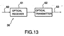
- the possible wavelength converter 36 comprises an input optical fiber 60, an optical receiver 61, and an optical transmitter 62, and an output optical fiber 63.
- An optical signal of a desired wavelength is supplied through the input optical fiber 60 to the optical receiver 61 to be converted into an electrical signal.
- the electrical signal is converted by the optical transmitter 62 back into the optical signal.
- the optical transmitter 62 has the zeroth wavelength ⁇ 0 as a transmission wavelength by way of example, wavelength conversion from the desired wavelength into the zeroth wavelength ⁇ 0 is achieved by the possible wavelength converter 36.
- the zeroth through the fifteenth wavelength converters 36-0 through 36-15 convert zeroth through fifteenth selected optical signals into zeroth through fifteenth wavelength converted optical signals, respectively.
- the zeroth through the seventh wavelength converted optical signals are supplied to the zeroth beam combiner 37-0.
- the eighth through the fifteenth wavelength converted optical signals are supplied to the first beam combiner 37-1.
- the zeroth beam combiner 37-0 combines the zeroth through the seventh wavelength converted optical signals to produce a zeroth WDM optical signal which is delivered to the zeroth output port 11-0.
- the first beam combiner 37-1 combines the eighth through the fifteenth wavelength converted optical signals to produce a first WDM optical signal which is supplied to the first output port 11-1.
- the optical switching apparatus of this embodiment has a function of a 16 x 16 crossbar network.
- connection between the zeroth wavelength ⁇ 0 of the zeroth input port 10-0 and the zeroth wavelength ⁇ 0 of the zeroth output port 11-0, and connection between the second wavelength ⁇ 2 of the first input port 10-1 and the first wavelength ⁇ 1 of the zeroth output port 11-0 are simultaneously carried out.
- the optical signal having the zeroth wavelength ⁇ 0 and supplied through the zeroth input port 10-0 passes through the zeroth input port i0 of the wavelength router 6 to the zeroth output port o0 to be supplied to the zeroth input port i0 of the optical space switch 32.
- the optical signal having the second wavelength ⁇ 2 and supplied through the first input port 10-1 passes through the first input port i1 of the wavelength router 6 to the zeroth output port o0 to be supplied to the zeroth input port i0 of the optical space switch 32.
- the optical space switch 32 multicasts to the zeroth and the first output ports o0 and o1 the WDM optical signal having the zeroth and the second wavelengths ⁇ 0 and ⁇ 2 and supplied from the zeroth input port i0.
- the zeroth wavelength selector 33-0 selects the optical signal having the zeroth wavelength ⁇ 0. This optical signal is converted by the zeroth wavelength converter 36-0 into the zeroth wavelength ⁇ 0 to be delivered through the zeroth beam combiner 37-0 to the zeroth output port 11-0.
- the first wavelength selector 33-1 selects the optical signal having the second wavelength ⁇ 2.
- This optical signal is converted by the first wavelength converter 36-1 into the first wavelength ⁇ 1 to be delivered through the first beam combiner 37-0 to the first output port 11-0.
- the connection from the zeroth wavelength ⁇ 0 on the zeroth input port 10-0 to the zeroth wavelength ⁇ 0 on the zeroth output port 11-0 and the connection from the second wavelength ⁇ 2 on the first input port 10-1 to the first wavelength ⁇ 1 on the zeroth output port 11-0 are simultaneously carried out.
- the wavelength router 6 serves as another optical converter to reduce the number of multiplexed wavelengths.
- the number of multiplexed wavelengths is equal to 8 and the number of multiplexed spaces is equal to 2.
- the number of multiplexed wavelengths is equal to 4 and the number of multiplexed spaces is equal to 4.
- the number of wavelengths used by the apparatus is equal to 8 in total.
- the number of multiplexed wavelengths on a single route is equal to 4 at maximum and the wavelength selectors 33 (suffixes omitted) similarly operate for both of the wavelength groups.
- the number of multiplexed wavelengths is reduced to 4.
- the number of the optical gate switches required in the apparatus is reduced. If the wavelength router 6 is not provided, the optical space switch 32 is of a 2 x 16 type while the wavelength selectors 33 is of a 8 x 1 type. Therefore, the number of the optical gate switches 22 required in the optical space switch 32 is equal to 32. The number of the optical gate switches 42 required per each wavelength selector 33 is equal to 8. Thus, the optical switching apparatus requires 160 optical gate switches in total. On the other hand, in this embodiment, the optical space switch 32 requires 64 optical gate switches while each wavelength selector 33 requires 4 optical gate switches. Thus, the optical switching apparatus of wavelength-division/space-division type according to this embodiment requires 128 optical gate switches in total. Thus, the number is reduced to 4/5 as compared with the case where the wavelength router 6 is not provided.
- the number of multiplexed wavelengths of the WDM optical signal supplied to the optical gate switch 22 of the optical space switch 32 is reduced so that the optical gate switch 22 as the semiconductor laser amplifier is hardly saturated.
- eight wavelengths are supplied to the optical gate switch 22 at maximum.
- four wavelengths are supplied at maximum.
- an intensity of optical signal for each wavelength can be increased to twice as compared with the case where the wavelength router 6 is not provided. Therefore, received power at the optical receiver 61 of the wavelength converter 36 (suffixes omitted) is increased to twice also.
- the zeroth through the seventh input WDM optical signals each of which has the zeroth and the first wavelengths ⁇ 0 and ⁇ 1 are supplied through the zeroth through the seventh input ports 10-0 through 10-7, respectively.
- the first, the third, the fifth, and the seventh input WDM optical signals are supplied to the zeroth through the third wavelength shifters 7-0 through 7-3, respectively.
- Each of the zeroth through the third wavelength shifters 7-0 through 7-3 wavelength-shifts the zeroth and the first wavelengths ⁇ 0 and ⁇ 1 of the input WDM optical signal supplied thereto into a wavelength-shifted WDM optical signal having the second and the third wavelengths ⁇ 2 and ⁇ 3.
- the zeroth wavelength shifter 7-0 wavelength-shifts the first input WDM optical signal to produce a zeroth wavelength-shifted WDM optical signal.
- the first wavelength shifter 7-1 wavelength-shifts the third input WDM optical signal to produce a first wavelength-shifted WDM optical signal.
- the second wavelength shifter 7-2 wavelength-shifts the fifth input WDM optical signal to produce a second wavelength-shifted WDM optical signal.
- the third wavelength shifter 7-3 wavelength-shifts the seventh input WDM optical signal to produce a third wavelength-shifted WDM optical signal.
- the wavelength shifters 7 (suffixes omitted) are similar in structure and operation to those of the second embodiment and will not be described any longer.
- the zeroth through the third wavelength-shifted WDM optical signals are supplied to one input ports of the zeroth through the third primary-stage beam combiners 8-0 through 8-3, respectively.
- the other input ports of the zeroth through the third primary-stage beam combiners 8-0 through 8-3 are also supplied with the zeroth, the second, the fourth, and the sixth input WDM optical signals each of which has the zeroth and the first wavelengths ⁇ 0 and ⁇ 1.
- the zeroth primary-stage beam combiner 8-0 combines the zeroth input WDM optical signal and the zeroth wavelength-shifted WDM optical signal to produce a zeroth primary-stage WDM optical signal having the zeroth through the third wavelengths ⁇ 0 through ⁇ 3.
- the first primary-stage beam combiner 8-1 combines the second input WDM optical signal and the first wavelength-shifted WDM optical signal to produce a first primary-stage WDM optical signal having the zeroth through the third wavelengths ⁇ 0 through ⁇ 3.
- the second primary-stage beam combiner 8-2 combines the fourth input WDM optical signal and the second wavelength-shifted WDM optical signal to produce a second primary-stage WDM optical signal having the zeroth through the third wavelengths ⁇ 0 through ⁇ 3.
- the third primary-stage beam combiner 8-3 combines the sixth input WDM optical signal and the third wavelength-shifted WDM optical signal to produce a third primary-stage WDM optical signal having the zeroth through the third wavelengths ⁇ 0 through ⁇ 3.
- the zeroth through the third primary-stage WDM optical signals are supplied to the optical space switch 32.
- the optical space switch 32 illustrated in the figure comprises a 4 x 16 optical crossbar switch adapted to perform 1-to-16 multicasting at maximum, and has the zeroth through the third input ports i0 through i3 and the zeroth through the fifteenth output ports o0 through o15.
- the optical space switch 32 directs the primary-stage WDM optical signal supplied through each input port to a desired output port. Herein, arbitration control is carried out so that those WDM optical signals supplied through different input ports are not outputted from any common output port.
- the optical space switch 32 in this embodiment is similar in structure and operation to that of the first embodiment and will not be described any longer.
- the optical space switch 32 produces the zeroth through the fifteenth switched WDM optical signals from the zeroth through the fifteenth output ports o0 through o15, respectively.
- the zeroth through the fifteenth switched WDM optical signals produced by the optical space switch 32 are supplied to the zeroth through the fifteenth wavelength selectors 33A-0 through 33A-15, respectively.
- Each of the wavelength selectors 33A selects and outputs a desired one of the four wavelengths of the switched WDM optical signal supplied thereto.
- the wavelength selectors 33A in this embodiment are similar in structure and operation to those in the second embodiment and will not be described any longer.
- the zeroth through the fifteenth wavelength selectors 33A-0 through 33A-15 select the optical signals of desired wavelengths from the zeroth through the fifteenth switched WDM optical signals and produce the zeroth through the fifteenth selected optical signals, respectively.
- the zeroth through the fifteenth selected optical signals produced by the zeroth through the fifteenth wavelength selectors 33A-0 through 33A-15 are supplied to the zeroth through the fifteenth wavelength converters 36A-0 through 36A-15, respectively.
- Each of the wavelength converters 36A (suffixes omitted) has a function of converting the wavelength of the input optical signal supplied thereto into a predetermined specific wavelength.
- the wavelength converters 36A are similar in structure and operation to the wavelength converters 36 in the third embodiment and will not be described any longer.
- the zeroth through the fifteenth wavelength converters 36A-0 through 36A-15 convert the zeroth through the fifteenth selected optical signals into the zeroth through the fifteenth wavelength-converted optical signals.
- each of the zeroth, the second, the fourth, the sixth, the eighth, the tenth, the twelfth, and the fourteenth wavelength-converted optical signals has the zeroth wavelength ⁇ 0 while each of the first, the third, the fifth, the seventh, the eleventh, the thirteenth, and the fifteenth wavelength-converted optical signals has the first wavelength ⁇ 1.
- the zeroth and the first wavelength-converted optical signals are supplied to a zeroth final-stage beam combiner 37A-0.
- the second and the third wavelength-converted optical signals are supplied to a first final-stage beam combiner 37A-1.
- the fourth and the fifth wavelength-converted optical signals are supplied to a second final-stage beam combiner 37A-2.
- the sixth and the seventh wavelength-converted optical signals are supplied to a third final-stage beam combiner 37A-3.
- the eighth and the ninth wavelength-converted optical signals are supplied to a fourth final-stage beam combiner 37A-4.
- the tenth and the eleventh wavelength-converted optical signals are supplied to a fifth final-stage beam combiners 37A-5.
- the twelfth and the thirteenth wavelength-converted optical signals are supplied to a sixth final-stage beam combiner 37A-6.
- the fourteenth and the fifteenth wavelength-converted optical signals are supplied to a seventh final-stage beam combiner 37A-7.
- the zeroth final-stage beam combiner 37A-0 combines the zeroth and the first wavelength-converted optical signals to produce a zeroth WDM optical signal which is delivered to the zeroth output port 11-0.
- the first final-stage beam combiner 37A-1 combines the second and the third wavelength-converted optical signals to produce a first WDM optical signal which is delivered to the first output port 11-1.
- the second final-stage beam combiner 37A-2 combines the fourth and the fifth wavelength-converted optical signals to produce a second WDM optical signal which is delivered to the second output port 11-2.
- the third final-stage beam combiner 37A-3 combines the sixth and the seventh wavelength-converted optical signals to produce a third WDM optical signal which is delivered to the third output port 11-3.
- the fourth final-stage beam combiner 37A-4 combines the eighth and the ninth wavelength-converted optical signals to produce a fourth WDM optical signal which is delivered to the fourth output port 11-4.
- the fifth final-stage beam combiner 37A-5 combines the tenth and the eleventh wavelength-converted optical signals to produce a fifth WDM optical signal which is delivered to the fifth output port 11-5.
- the sixth final-stage beam combiner 37A-6 combines the twelfth and the thirteenth wavelength-converted optical signals to produce a sixth WDM optical signal which is delivered to the sixth output port 11-6.
- the seventh final-stage beam combiner 37A-7 combines the fourteenth and the fifteenth wavelength-converted optical signals to produce a seventh WDM optical signal which is delivered to the seventh output port 11-7.
- the optical switching apparatus of wavelength-division/space-division type has a function of a 16 x 16 crossbar network.
- connection between the optical signal having the zeroth wavelength ⁇ 0 on the zeroth input port 10-0 and the optical signal having the zeroth wavelength ⁇ 0 on the zeroth output port 11-0, and connection between the optical signal having the zeroth wavelength ⁇ 0 on the first input port 10-1 and the optical signal having the first wavelength ⁇ 1 on the zeroth output port 11-0 are simultaneously carried out.
- the optical signal having the zeroth wavelength ⁇ 0 and supplied from the zeroth input port 10-0 passes through the zeroth primary-stage beam combiner 8-0 to be supplied to the zeroth input port of the optical space switch 32.
- the optical signal having the zeroth wavelength ⁇ 0 and supplied from the first input port 10-1 is wavelength-shifted by the zeroth wavelength shifter 7-0 into an optical signal having the second wavelength ⁇ 2 which is delivered through the zeroth primary-stage beam combiner 8-0 to be supplied to the zeroth input port i0 of the optical space switch 32.
- the optical space switch 32 multicasts to the zeroth and the first output ports o0 and o1 the WDM optical signal having the zeroth and the second wavelengths ⁇ 0 and ⁇ 2 and supplied from the zeroth input port i0.
- the zeroth wavelength selector 33A-0 selects the optical signal having the zeroth wavelength ⁇ 0.
- This optical signal is converted by the zeroth wavelength converter 36A-0 into the optical signal having the zeroth wavelength ⁇ 0 which is delivered through the zeroth final-stage beam combiner 37A-0 to the zeroth output port 11-0.
- the first wavelength selector 33A-1 selects the optical signal having the second wavelength ⁇ 2.
- the optical signal is converted by the first wavelength converter 36A-1 into the optical signal having the first wavelength ⁇ 1 which is delivered through the zeroth final-stage beam combiner 37A-0 to the zeroth output port 11-0.
- connection from the optical signal having the zeroth wavelength ⁇ 0 on the zeroth input port 10-0 to the optical signal having the zeroth wavelength ⁇ 0 on the zeroth output port 11-0, and the connection from the optical signal having the zeroth wavelength ⁇ 0 on the first input port 10-1 to the optical signal having the first wavelength ⁇ 1 on the zeroth output port 11-0 are simultaneously achieved.
- the wavelength shifters 7 serve as another optical converter to increase the number of multiplexed wavelengths.
- the number of multiplexed wavelengths is equal to 2 while the number of multiplexed spaces is equal to 8.
- the number of multiplexed wavelengths is equal to 4 and the number of multiplexed spaces is equal to 4.
- the optical space switch 32 is of an 8 x 16 type while the wavelength selector 33 is of a 2 x 1 type. Therefore, the optical gate switches 22 required in the optical space switch 32 is equal to 128 while the optical gate switches 42 required per each wavelength selector 33 is equal to 2.
- the optical switching apparatus requires 160 optical gate switches in total.
- the optical space switch 32 requires 64 optical gate switches while each wavelength selector 33 requires 4 optical gate switches.
- the optical switching apparatus of wavelength-division/space-division type requires 128 optical gate switches in total.
- the number is reduced to 4/5 as compared with the case where the wavelength shifters 7 (suffixes omitted) and the next-stage beam combiners 8 (suffixes omitted) are not provided.
- the wavelength routers comprise optical converters.
- the wavelength shifters and the secondary-stage beam combiners comprise optical converters.
- the optical converter is not restricted to the above-mentioned structure but may be another structure which has a function adapted to the present invention.
- the optical space switch 32 is of splitter/combiner type using the optical gate switches.
- the optical space switch is not restricted to the above-mentioned structure but may be an optical matrix switch made of lithium niobate or the like and having an electro-optic effect or an acousto-optic effect, a mechanical optical switch, or a liquid-crystal optical switch.
- each of the wavelength selectors 33 (suffixes omitted) and 33A (suffixes omitted) comprises the wavelength demultiplexer, the optical gate switch, and the beam combiner.
- the wavelength selector is not restricted to the above-mentioned structure but may comprise a combination of the wavelength demultiplexer and the optical matrix switch, or a wavelength tunable optical filter such as an acousto-optic optical filter, a fiber Fabry-Pérot optical filter, and a angle-tuned interference optical filter.
- the optical gate switch in the optical space switch 32 and the wavelength selector 33 or 33A comprises a semiconductor laser amplifier.
- the optical gate switch is not restricted to the above-mentioned structure but may comprise a electro-absorption optical modulator formed by a semiconductor, an optical gate switch made of lithium niobate having the electro-optic effect or the acousto-optic effect, a mechanical optical switch, or a liquid-crystal optical switch.
- the wavelength router 6 comprises a silica arrayed-waveguide grating-type device formed on the silicon substrate.
- the wavelength router is not restricted to the above-mentioned structure but may be an arrayed-waveguide grating type device formed on a semiconductor substrate, a reflection-type grating device, or a Fabry-Pérot optical filter, a Mach-Zehnder optical filter, an interference optical filter, and a combination thereof.
- each of the wavelength shifters 7 (suffixes omitted) utilizes four-wave-mixing in the semiconductor laser amplifier.
- the wavelength shifter is not restricted to the above-mentioned structure but may utilize four-wave-mixing in the optical fiber.
- each of the wavelength converters 36 (suffixes omitted) and 36A (suffixes omitted) comprises a combination of the optical receiver and the optical transmitter.
- the wavelength converter is not restricted to the above-mentioned structure but may utilize four-wave-mixing in a medium such as a semiconductor and silica or may utilize a nonlinear optical effect such as a cross gain modulation.
- the optical switching apparatus of wavelength-division/space-division type comprises a combination of the optical space switch, the wavelength selector, the wavelength converter, and the beam combiner.
- the apparatus of wavelength-division/space-division type is not restricted to the above-mentioned structure but may comprise a combination of the wavelength demultiplexer, the optical space switch, the wavelength converter, and the beam combiner.
- the third and the fourth embodiments of this invention it is possible to reduce the number of multiplexed wavelengths in the optical switching apparatus of space division type or in the optical switching apparatus of wavelength-division/space-division type.
Landscapes
- Engineering & Computer Science (AREA)
- Computer Networks & Wireless Communication (AREA)
- Optical Communication System (AREA)
- Use Of Switch Circuits For Exchanges And Methods Of Control Of Multiplex Exchanges (AREA)
Applications Claiming Priority (2)
| Application Number | Priority Date | Filing Date | Title |
|---|---|---|---|
| JP10079500A JPH11275614A (ja) | 1998-03-26 | 1998-03-26 | 光交換装置 |
| JP7950098 | 1998-03-26 |
Publications (1)
| Publication Number | Publication Date |
|---|---|
| EP0946077A2 true EP0946077A2 (de) | 1999-09-29 |
Family
ID=13691657
Family Applications (1)
| Application Number | Title | Priority Date | Filing Date |
|---|---|---|---|
| EP99105133A Withdrawn EP0946077A2 (de) | 1998-03-26 | 1999-03-26 | Optische Vermittlungseinrichtung mit Wellenlängenmultiplex-Technik |
Country Status (4)
| Country | Link |
|---|---|
| US (1) | US6445473B1 (de) |
| EP (1) | EP0946077A2 (de) |
| JP (1) | JPH11275614A (de) |
| CA (1) | CA2266967A1 (de) |
Cited By (1)
| Publication number | Priority date | Publication date | Assignee | Title |
|---|---|---|---|---|
| WO2001074112A1 (en) * | 2000-03-28 | 2001-10-04 | Ditech Communications Corporation | A tunable filter |
Families Citing this family (10)
| Publication number | Priority date | Publication date | Assignee | Title |
|---|---|---|---|---|
| JP4567830B2 (ja) * | 1999-11-29 | 2010-10-20 | 三菱電機株式会社 | 光波長多重伝送方式 |
| US20020126349A1 (en) * | 2001-03-12 | 2002-09-12 | Mohsen Sarraf | Multiplexing information on multiple wavelengths in optical systems |
| JP2003021795A (ja) | 2001-07-09 | 2003-01-24 | Nec Corp | 光スイッチシステム |
| JP4009946B2 (ja) * | 2003-01-16 | 2007-11-21 | 横河電機株式会社 | 光経路制御装置 |
| US7313329B2 (en) * | 2003-09-04 | 2007-12-25 | The Regents Of The University Of California | All optical variable buffer queue useful in optical packet networks |
| US7200299B1 (en) * | 2006-03-23 | 2007-04-03 | Lucent Technologies Inc. | Adding and dropping wavelength-channels |
| GB2452180B (en) * | 2006-05-25 | 2011-08-24 | Fujitsu Ltd | Optical access network system |
| US9729946B2 (en) * | 2009-04-03 | 2017-08-08 | Infinera Corporation | High-capacity switch |
| CN103558667B (zh) * | 2013-11-19 | 2016-04-13 | 武汉光迅科技股份有限公司 | 一种基于自由空间传输的多播交换光开关 |
| JP6223931B2 (ja) * | 2014-09-02 | 2017-11-01 | 日本電信電話株式会社 | 光増幅装置 |
Family Cites Families (22)
| Publication number | Priority date | Publication date | Assignee | Title |
|---|---|---|---|---|
| DE3853935T2 (de) * | 1987-09-30 | 1995-10-12 | Nippon Electric Co | Zeit- und Wellenlängenmultiplex-Vermittlungssystem. |
| JP2545100B2 (ja) | 1987-10-23 | 1996-10-16 | 富士通株式会社 | 波長分割交換システム |
| JPH0712230B2 (ja) | 1988-07-18 | 1995-02-08 | 富士通株式会社 | 光交換システム |
| JPH03100526A (ja) | 1989-09-14 | 1991-04-25 | Hitachi Ltd | 光スイッチアレイ |
| JP2692316B2 (ja) * | 1989-11-20 | 1997-12-17 | 日本電気株式会社 | 波長分割光交換機 |
| DE4028556C1 (de) | 1990-09-08 | 1992-04-02 | Robert Bosch Gmbh, 7000 Stuttgart, De | |
| CA2055546C (en) * | 1990-11-14 | 1999-02-02 | Shuji Suzuki | Self-routing network using optical gate array driven by control voltages coincidental with packet header pulses |
| SE469149B (sv) * | 1990-12-07 | 1993-05-17 | Ellemtel Utvecklings Ab | Optisk vaeljare, optisk korskopplare och saett att omkoppla grupper av optiska signaler |
| IT1257546B (it) * | 1992-06-15 | 1996-01-30 | Cselt Centro Studi Lab Telecom | Commutatore ottico per reti a commutazione veloce di cella. |
| EP0618291A3 (de) * | 1993-02-26 | 1997-12-03 | Takeda Chemical Industries, Ltd. | PACAP-Rezeptor Protein, Verfahren zur dessen Herstellung und Verwendung davon |
| JPH0759127A (ja) | 1993-08-18 | 1995-03-03 | Fujitsu Ltd | 時分割・波長分割融合型光スイッチ |
| JP3100526B2 (ja) | 1994-01-28 | 2000-10-16 | 松下電器産業株式会社 | スイッチング電源装置 |
| US5475679A (en) * | 1994-12-08 | 1995-12-12 | Northern Telecom Limited | Large capacity ATM switch |
| DE59607789D1 (de) * | 1995-06-08 | 2001-10-31 | Siemens Ag | Blockierungsfreie multicast wdm-koppelanordnung |
| JP3582030B2 (ja) * | 1995-07-05 | 2004-10-27 | 富士通株式会社 | クロスコネクト装置 |
| FR2736777B1 (fr) * | 1995-07-12 | 1997-08-08 | Alcatel Nv | Reseau de transmission optique avec multiplexage de longueurs d'onde |
| US6097517A (en) * | 1995-09-01 | 2000-08-01 | Oki Electric Industry Co., Ltd. | Wavelength router |
| US6013076A (en) * | 1996-01-09 | 2000-01-11 | Gyrus Medical Limited | Electrosurgical instrument |
| US6271949B1 (en) * | 1996-12-18 | 2001-08-07 | Nec Corporation | Optical communication system using wavelength-division multiplexed light |
| JP2964984B2 (ja) * | 1997-04-03 | 1999-10-18 | 日本電気株式会社 | 光スイッチ装置 |
| JP3102379B2 (ja) * | 1997-04-30 | 2000-10-23 | 日本電気株式会社 | 波長多重光伝送システム用監視制御方式 |
| EP1017242B1 (de) | 1998-12-28 | 2007-01-31 | STMicroelectronics S.r.l. | Optische Querverbindungsarchitektur für WDM-Telekommunikationssysteme |
-
1998
- 1998-03-26 JP JP10079500A patent/JPH11275614A/ja active Pending
-
1999
- 1999-03-25 CA CA002266967A patent/CA2266967A1/en not_active Abandoned
- 1999-03-26 US US09/276,671 patent/US6445473B1/en not_active Expired - Fee Related
- 1999-03-26 EP EP99105133A patent/EP0946077A2/de not_active Withdrawn
Cited By (2)
| Publication number | Priority date | Publication date | Assignee | Title |
|---|---|---|---|---|
| WO2001074112A1 (en) * | 2000-03-28 | 2001-10-04 | Ditech Communications Corporation | A tunable filter |
| GB2377331A (en) * | 2000-03-28 | 2003-01-08 | Ditech Comm Corp | A tunable filter |
Also Published As
| Publication number | Publication date |
|---|---|
| CA2266967A1 (en) | 1999-09-26 |
| JPH11275614A (ja) | 1999-10-08 |
| US6445473B1 (en) | 2002-09-03 |
Similar Documents
| Publication | Publication Date | Title |
|---|---|---|
| US5739935A (en) | Modular optical cross-connect architecture with optical wavelength switching | |
| JP3845450B2 (ja) | 光波長交換によるモジュラオプティカルクロスコネクトアーキテクチャ | |
| US5623356A (en) | Combined wavelength router and switch apparatus for use in a wavelength division multiplexed optical communication system | |
| EP0382431B1 (de) | Kommunikationsnetzwerk | |
| US4845703A (en) | Wavelength division optical switching system having wavelength switching light modulators | |
| JP3139540B2 (ja) | 光スイッチ網 | |
| US6271949B1 (en) | Optical communication system using wavelength-division multiplexed light | |
| US20150180606A1 (en) | Optical line terminal arrangement, apparatus and methods | |
| JPH11313351A (ja) | 光ネットワ―クにおいて光信号を多重化する装置および記憶媒体。 | |
| EP0946077A2 (de) | Optische Vermittlungseinrichtung mit Wellenlängenmultiplex-Technik | |
| US9729946B2 (en) | High-capacity switch | |
| US9025915B2 (en) | Method and module for switching optical signals having different modes of propagation | |
| US20030206743A1 (en) | Cross connecting device and optical communication system | |
| US6574386B1 (en) | Dynamically reconfigurable optical switching system | |
| EP1043847B1 (de) | Wdm-übertragungsnetzwerkvorrichtung mit sender/empfänger mit optischem schalter mit 2 eingängen und 2 ausgängen | |
| JP3574754B2 (ja) | 光パスクロスコネクト装置 | |
| JP4176382B2 (ja) | 光情報トランスポートを多重化する方法 | |
| JP2004135331A (ja) | 光回線分配システム | |
| US20040258411A1 (en) | Node for an optical network | |
| EP1017243A2 (de) | Optischer Schalter und optisch geschaltetes Netzwerk | |
| JP3818448B2 (ja) | 光クロスコネクト装置 | |
| KR100373321B1 (ko) | 파장분할광스위칭장치 | |
| JPH066844A (ja) | 波長分割多重光クロスコネクトスイッチ装置 | |
| JP3909656B2 (ja) | 複数波長一括波長変換装置 | |
| WO2022206191A1 (zh) | 光通信系统和光通信方法 |
Legal Events
| Date | Code | Title | Description |
|---|---|---|---|
| PUAI | Public reference made under article 153(3) epc to a published international application that has entered the european phase |
Free format text: ORIGINAL CODE: 0009012 |
|
| AK | Designated contracting states |
Kind code of ref document: A2 Designated state(s): AT BE CH CY DE DK ES FI FR GB GR IE IT LI LU MC NL PT SE |
|
| AX | Request for extension of the european patent |
Free format text: AL;LT;LV;MK;RO;SI |
|
| STAA | Information on the status of an ep patent application or granted ep patent |
Free format text: STATUS: THE APPLICATION HAS BEEN WITHDRAWN |
|
| 18W | Application withdrawn |
Effective date: 20030613 |