EP0947183A2 - Laserbehandlungsvorrichtung - Google Patents
Laserbehandlungsvorrichtung Download PDFInfo
- Publication number
- EP0947183A2 EP0947183A2 EP99105503A EP99105503A EP0947183A2 EP 0947183 A2 EP0947183 A2 EP 0947183A2 EP 99105503 A EP99105503 A EP 99105503A EP 99105503 A EP99105503 A EP 99105503A EP 0947183 A2 EP0947183 A2 EP 0947183A2
- Authority
- EP
- European Patent Office
- Prior art keywords
- light
- laser
- treatment apparatus
- eye
- laser beam
- Prior art date
- Legal status (The legal status is an assumption and is not a legal conclusion. Google has not performed a legal analysis and makes no representation as to the accuracy of the status listed.)
- Granted
Links
- 238000013532 laser treatment Methods 0.000 title claims abstract description 40
- 230000003287 optical effect Effects 0.000 claims abstract description 56
- 238000011282 treatment Methods 0.000 claims abstract description 28
- 230000001678 irradiating effect Effects 0.000 claims abstract description 5
- 230000000007 visual effect Effects 0.000 claims description 24
- 210000000695 crystalline len Anatomy 0.000 description 25
- 238000005286 illumination Methods 0.000 description 20
- 230000004044 response Effects 0.000 description 10
- 230000004907 flux Effects 0.000 description 5
- 238000001514 detection method Methods 0.000 description 4
- 239000004065 semiconductor Substances 0.000 description 4
- 230000008859 change Effects 0.000 description 3
- 238000012986 modification Methods 0.000 description 3
- 230000004048 modification Effects 0.000 description 3
- 208000010412 Glaucoma Diseases 0.000 description 2
- 206010036346 Posterior capsule opacification Diseases 0.000 description 2
- 230000033228 biological regulation Effects 0.000 description 2
- 239000012141 concentrate Substances 0.000 description 2
- 230000001186 cumulative effect Effects 0.000 description 2
- 238000010586 diagram Methods 0.000 description 2
- 230000006870 function Effects 0.000 description 2
- 239000013307 optical fiber Substances 0.000 description 2
- 238000010079 rubber tapping Methods 0.000 description 2
- 239000007787 solid Substances 0.000 description 2
- 208000008516 Capsule Opacification Diseases 0.000 description 1
- 208000002177 Cataract Diseases 0.000 description 1
- 208000035719 Maculopathy Diseases 0.000 description 1
- 206010038848 Retinal detachment Diseases 0.000 description 1
- 230000002159 abnormal effect Effects 0.000 description 1
- 230000032683 aging Effects 0.000 description 1
- 230000005540 biological transmission Effects 0.000 description 1
- 239000002775 capsule Substances 0.000 description 1
- 230000015271 coagulation Effects 0.000 description 1
- 238000005345 coagulation Methods 0.000 description 1
- 238000012790 confirmation Methods 0.000 description 1
- 230000021615 conjugation Effects 0.000 description 1
- 230000006378 damage Effects 0.000 description 1
- 230000007423 decrease Effects 0.000 description 1
- 230000003247 decreasing effect Effects 0.000 description 1
- 238000009792 diffusion process Methods 0.000 description 1
- 201000010099 disease Diseases 0.000 description 1
- 208000037265 diseases, disorders, signs and symptoms Diseases 0.000 description 1
- 229910052743 krypton Inorganic materials 0.000 description 1
- DNNSSWSSYDEUBZ-UHFFFAOYSA-N krypton atom Chemical compound [Kr] DNNSSWSSYDEUBZ-UHFFFAOYSA-N 0.000 description 1
- 208000002780 macular degeneration Diseases 0.000 description 1
- 208000038015 macular disease Diseases 0.000 description 1
- 230000002093 peripheral effect Effects 0.000 description 1
- 230000000649 photocoagulation Effects 0.000 description 1
- 230000000717 retained effect Effects 0.000 description 1
- 230000004264 retinal detachment Effects 0.000 description 1
Images




Classifications
-
- A—HUMAN NECESSITIES
- A61—MEDICAL OR VETERINARY SCIENCE; HYGIENE
- A61F—FILTERS IMPLANTABLE INTO BLOOD VESSELS; PROSTHESES; DEVICES PROVIDING PATENCY TO, OR PREVENTING COLLAPSING OF, TUBULAR STRUCTURES OF THE BODY, e.g. STENTS; ORTHOPAEDIC, NURSING OR CONTRACEPTIVE DEVICES; FOMENTATION; TREATMENT OR PROTECTION OF EYES OR EARS; BANDAGES, DRESSINGS OR ABSORBENT PADS; FIRST-AID KITS
- A61F9/00—Methods or devices for treatment of the eyes; Devices for putting in contact-lenses; Devices to correct squinting; Apparatus to guide the blind; Protective devices for the eyes, carried on the body or in the hand
- A61F9/007—Methods or devices for eye surgery
- A61F9/008—Methods or devices for eye surgery using laser
-
- A—HUMAN NECESSITIES
- A61—MEDICAL OR VETERINARY SCIENCE; HYGIENE
- A61F—FILTERS IMPLANTABLE INTO BLOOD VESSELS; PROSTHESES; DEVICES PROVIDING PATENCY TO, OR PREVENTING COLLAPSING OF, TUBULAR STRUCTURES OF THE BODY, e.g. STENTS; ORTHOPAEDIC, NURSING OR CONTRACEPTIVE DEVICES; FOMENTATION; TREATMENT OR PROTECTION OF EYES OR EARS; BANDAGES, DRESSINGS OR ABSORBENT PADS; FIRST-AID KITS
- A61F9/00—Methods or devices for treatment of the eyes; Devices for putting in contact-lenses; Devices to correct squinting; Apparatus to guide the blind; Protective devices for the eyes, carried on the body or in the hand
- A61F9/007—Methods or devices for eye surgery
- A61F9/008—Methods or devices for eye surgery using laser
- A61F9/00821—Methods or devices for eye surgery using laser for coagulation
-
- A—HUMAN NECESSITIES
- A61—MEDICAL OR VETERINARY SCIENCE; HYGIENE
- A61F—FILTERS IMPLANTABLE INTO BLOOD VESSELS; PROSTHESES; DEVICES PROVIDING PATENCY TO, OR PREVENTING COLLAPSING OF, TUBULAR STRUCTURES OF THE BODY, e.g. STENTS; ORTHOPAEDIC, NURSING OR CONTRACEPTIVE DEVICES; FOMENTATION; TREATMENT OR PROTECTION OF EYES OR EARS; BANDAGES, DRESSINGS OR ABSORBENT PADS; FIRST-AID KITS
- A61F9/00—Methods or devices for treatment of the eyes; Devices for putting in contact-lenses; Devices to correct squinting; Apparatus to guide the blind; Protective devices for the eyes, carried on the body or in the hand
- A61F9/007—Methods or devices for eye surgery
- A61F9/008—Methods or devices for eye surgery using laser
- A61F2009/00855—Calibration of the laser system
-
- A—HUMAN NECESSITIES
- A61—MEDICAL OR VETERINARY SCIENCE; HYGIENE
- A61F—FILTERS IMPLANTABLE INTO BLOOD VESSELS; PROSTHESES; DEVICES PROVIDING PATENCY TO, OR PREVENTING COLLAPSING OF, TUBULAR STRUCTURES OF THE BODY, e.g. STENTS; ORTHOPAEDIC, NURSING OR CONTRACEPTIVE DEVICES; FOMENTATION; TREATMENT OR PROTECTION OF EYES OR EARS; BANDAGES, DRESSINGS OR ABSORBENT PADS; FIRST-AID KITS
- A61F9/00—Methods or devices for treatment of the eyes; Devices for putting in contact-lenses; Devices to correct squinting; Apparatus to guide the blind; Protective devices for the eyes, carried on the body or in the hand
- A61F9/007—Methods or devices for eye surgery
- A61F9/008—Methods or devices for eye surgery using laser
- A61F2009/00861—Methods or devices for eye surgery using laser adapted for treatment at a particular location
- A61F2009/00863—Retina
-
- A—HUMAN NECESSITIES
- A61—MEDICAL OR VETERINARY SCIENCE; HYGIENE
- A61F—FILTERS IMPLANTABLE INTO BLOOD VESSELS; PROSTHESES; DEVICES PROVIDING PATENCY TO, OR PREVENTING COLLAPSING OF, TUBULAR STRUCTURES OF THE BODY, e.g. STENTS; ORTHOPAEDIC, NURSING OR CONTRACEPTIVE DEVICES; FOMENTATION; TREATMENT OR PROTECTION OF EYES OR EARS; BANDAGES, DRESSINGS OR ABSORBENT PADS; FIRST-AID KITS
- A61F9/00—Methods or devices for treatment of the eyes; Devices for putting in contact-lenses; Devices to correct squinting; Apparatus to guide the blind; Protective devices for the eyes, carried on the body or in the hand
- A61F9/007—Methods or devices for eye surgery
- A61F9/008—Methods or devices for eye surgery using laser
- A61F2009/00885—Methods or devices for eye surgery using laser for treating a particular disease
- A61F2009/00891—Glaucoma
-
- A—HUMAN NECESSITIES
- A61—MEDICAL OR VETERINARY SCIENCE; HYGIENE
- A61F—FILTERS IMPLANTABLE INTO BLOOD VESSELS; PROSTHESES; DEVICES PROVIDING PATENCY TO, OR PREVENTING COLLAPSING OF, TUBULAR STRUCTURES OF THE BODY, e.g. STENTS; ORTHOPAEDIC, NURSING OR CONTRACEPTIVE DEVICES; FOMENTATION; TREATMENT OR PROTECTION OF EYES OR EARS; BANDAGES, DRESSINGS OR ABSORBENT PADS; FIRST-AID KITS
- A61F9/00—Methods or devices for treatment of the eyes; Devices for putting in contact-lenses; Devices to correct squinting; Apparatus to guide the blind; Protective devices for the eyes, carried on the body or in the hand
- A61F9/007—Methods or devices for eye surgery
- A61F9/008—Methods or devices for eye surgery using laser
- A61F9/009—Auxiliary devices making contact with the eyeball and coupling in laser light, e.g. goniolenses
Definitions
- the present invention relates to a laser treatment apparatus for treating an affected part of a patient by irradiating a laser beam the affected part to be treated with a laser beam.
- the above-mentioned typical laser treatments need a relatively and accurately specified irradiation spot.
- An operator therefore has to specify the irradiation spot during his magnification-observation of the patient's eye including the affected part through an observation optical system, and conducts the laser treatments.
- a slit lamp is generally used for the observation optical system.
- the observation of the affected part illuminated by an illumination light are often performed in a state where the lightness of the using environment of the apparatus is lowered in order to reduce the influence of interference light from the surroundings of the apparatus, thereby to make easy to observe the interior of the patient's eye.
- a laser treatment apparatus of a first type in which a control panel is disposed opposite to the operator, namely below eyepieces of the observation optical system.
- the control panel is provided with a display part using a light emitting element such as an LED to allow the operator to look set values.
- the operator in using the apparatus of the first type, the operator must detach his eyes from the eyepieces of the slit lamp finder and look the settings displayed on the control panel to confirm as to whether or not the condition of the treatment laser beam is set in correspondence to the purpose of treatment to be carried out.
- Such the confirmation by the detachment of operator's eyes from the finder every time before the laser irradiation is troublesome for the operator. Meanwhile, the patient is kept waiting. The operator can not also concentrate his attention on the observation of the affected part of the patient's eye. If the operator does not detach his eyes from the finder during the laser treatment, he can not confirm whether the set condition of the treatment laser beam answers the treatment purpose.
- the information is displayed at the constant brightness level within the visual field of the finder.
- the brightness of the observation visual field which varies with the observed region of the patient's eye and the illumination light quantity, therefore, the observed region and the displayed information are hard to view.
- the bright observation visual field causes difficulty in discriminating the displayed information
- the dark visual field gives a feeling of glaring to the operator's eyes and causes difficulty in viewing the observed region.
- the present invention has been made in view of the above circumstances and has an object to overcome the above problems and to provide a laser treatment apparatus capable of improving visibility of information display and a region to be observed during a laser treatment, thereby to reduce a burden on a patient.
- a laser treatment apparatus for performing treatments on a patient's eye by irradiating the eye with a laser beam
- the apparatus comprising an observation optical system including eyepieces through which the patient's eye is observed by an operator, a setting device for setting irradiation conditions of the laser beam, a display part for displaying information of the irradiation conditions set by the setting device, a light detector for detecting a light quantity, and an adjuster for adjusting brightness of the display part based on the light quantity detected by the light detector.
- the above apparatus may be arranged such that the display part is disposed near the eyepieces and the light detector detects a light quantity of an extraneous light with respect to the apparatus.
- the above apparatus may also be arranged such that the display part displays the information of the irradiation conditions within an observation visual field viewed through the eyepieces, and the light detector detects a light quantity of a reflected light reflected by a portion of the patient's eye observed through the eyepieces.
- the above apparatus may comprise a laser emitter for emitting a laser beam having a desired wavelength selected from a plurality of wavelengths
- the setting device may include a selector for selecting a wavelength of the laser beam to irradiate an affected part of the patient's eye
- the display part may display information of the wavelength of the laser beam selected by the selector within an observation visual field viewed through the eyepieces.
- the light quantity of the display part is controlled based on the light quantity of the light reflected by the part of the patient's eye or the extraneous light with respect to the apparatus. Accordingly, the displayed information and the observed part of the eye can be satisfactorily observed by the operator to make smooth alignment for laser treatment, and a burden on the patient's eye can be reduced.
- FIG. 1 is a schematic perspective view of the laser treatment apparatus.
- Fig. 2 is a schematic view of the major components of a control system and an optical system of the apparatus.
- a laser oscillator 1 is provided with a treatment laser source 10, a light delivery optical system, and others.
- the laser source 10 has a solid laser rod, an optically pumped light source, and Q-switch, and others not shown.
- the laser source 10 can generates for a short time giant pulses which have a narrow pulse width and a large output peak.
- Used for the solid laser rod is an Nd:YAG rod which oscillates light having a basic wavelength of 1064 nm.
- a beam splitter 11 In the laser oscillator 1, there are provided a beam splitter 11, a light detector 12, a safety shatter 13, and a solenoid 14.
- the shatter 13 is insertable onto the optical axis of a laser beam from the laser source 10 thereby to ensure the safety at the time of the laser irradiation.
- Aiming light emitted from an aging light source 15 using semiconductor laser is made into parallel luminous flux by a collimator lens 16, divided into two light beams by an aperture 17 formed with two holes.
- the light beams are reflected by a dichroic mirror 18 and delivered to a patient's eye E through a dichroic mirror 19 disposed in a slit lamp delivery 4 of which the details will be mentioned later.
- Numeral 2 is a stand which is vertically movable.
- Numeral 3 is a control panel for setting laser irradiation conditions. As shown in Fig. 3, the control panel 3 is provided with an input switch group 31 and a light emitting display section 32.
- Fig. 3 is an example of the arrangement of the switch group 31 and the light emitting display section 32 on the control panel 3.
- the input switch group 31 includes a READY switch 31a for setting the laser irradiation ready state of the apparatus, a PULSE/BURST setting switch 31b for setting the number of laser irradiation in response to one trigger signal, and a COUNTER-RESET switch 31c for resetting a COUNTER display part 32e which displays the cumulative number of irradiation.
- the display section 32 includes a READY lamp 32a for displaying the irradiation ready state of the apparatus, an AIMING-OFF lamp 32b for indicating a lighting-on/off of an aiming light, an ENERGY display part 32c for indicating the set intensity of laser energy, a PULSE/BURST display part 32d for displaying the number of irradiation set with the setting switch 31b, a COUNTER display part 32e for displaying the cumulative number of irradiation, a FOCUS-SHIFT display part 32f for displaying the amount of a shift of a focus point of a laser beam from a focus point of the aiming light, and a LASER-EMISSION lamp 32g which is lighted when the power supply to the apparatus is turned on.
- the display section 32 displays the conditions, which are set through the switch groups 31 and an energy regulation knob 7, by the use of light emitting elements such as LED and the like.
- Numeral 4 is a slit lamp delivery for observing the patient's eye E. While observing the eye E through this slit lamp delivery 4, the operator can perform laser irradiation to the affected part of the eye E through the laser oscillator 1.
- the slit lamp delivery 4 is structured of eyepieces 4a, a microscope part 4b which holds the observation optical system, and an illumination part 4c which holds the illumination optical system.
- the illumination part 4c can emit a spot light which is linearly changeable in diameter in a range of 0.2-8.0 mm.
- the microscope part 4b is provided with an objective lens 41 which is in common used between right and left observation optical paths, a variable magnification optical system 42, an image forming lens 43, erect prisms 44, a field stop 45, and an eyepiece 46, the elements from 42 to 46 being disposed in each of the right and left optical paths.
- the variable magnification optical system 42 is so constructed as to be properly switched according to a set magnification.
- an operator's safety filter is inserted onto the optical path between the lenses 41 and 43.
- a well known optical system is used for a structure of the illumination optical system of the illumination part 4c. The structure of this optical system is less related to the present invention and its detailed description is omitted in this specification.
- Numeral 5 is a joystick for specifying the laser irradiation spot.
- Numeral 6 is a light sensor 6 for detecting the light quantity of an extraneous light.
- the joystick 5 is provided thereon with a trigger switch 5a for generating a trigger signal for laser irradiation.
- the light sensor 6 is disposed near the control panel 3.
- the lamp 32g When the power supply to the apparatus is turned on by the operator, the lamp 32g is lighted and, after several seconds, test irradiation is started.
- the test irradiation is carried out in a state where the shatter 13 is inserted on the optical axis.
- the laser beam emitted from the laser light source 10 is reflected by the beam splitter 11 and enters the light detector 12.
- a control section 20 calculates the intensity of laser energy based on the light reception quantity detected by the light detector 12 to display the intensity on the display section 32c in 1/10 mJ (millijoule) unit.
- the test irradiation is conducted every time the energy intensity is set with the knob 7.
- the laser energy intensity detected by the detector 12 is each time displayed on the display section 32c.
- the operator sets irradiation conditions including laser output energy, the number of irradiation pulses, and so on in response to the treatment purpose with respect to the patient's eye E.
- the light sensor 6 detects a large quantity of light.
- the control section 20 thus controls the amount of current to be supplied to the display section 32 based on the light reception quantity by the sensor 6 so that the display section 32 is more lighted, thereby enabling the operator to easily confirm the setting conditions even in the lighted room.
- the operator Upon completion of the setting, the operator places the patient at a predetermined position and lowers the room's light which will become interference light, in order to ensure the easiness of observation of the part to be treated of the patient's eye E.
- the setting may be conducted in the room of which the light is lowered from the start.
- the control section 20 reduces the amount of current to be supplied to the display section 32 in response to the light reception quantity, thereby to reduce the light quantity of display emitting elements and lowers the brightness level of the display section 32.
- the display light quantity of the display section 32 with respect to the ambient lightness is controlled in accordance with programs such as a table, a calculation expression, etc. stored in a memory 21 in advance.
- the display light quantity may be varied linearly in response to the light reception quantity by the light sensor 6, as shown in Fig. 4(a). Alternately, it may be varied in multiple steps in response to the light reception quantity as shown in Fig. 4(b).
- the horizontal axis of a graph shown in Figs. 4(a) and 4(b) indicate the lightness (lux) of the room in logarithm table.
- the lightness of the room is generally 400-500 lux under a fluorescent light and 1-2 lux under dim light in a darkroom.
- the vertical axis of the graph shown in Figs. 4(a) and 4(b) indicate the lightness of display (microradians), which is 3 mcd at the maximum and 1.5 mcd at the minimum by turning on the room's light at 50% of a duty ratio under duty control.
- the operator performs alignment to adjust a sight of the aiming light to the affected part of the patient's eye E while observing the eye E through the observation optical system from the eyepieces 4a of the slit lamp delivery 4.
- the degree of the display light quantity of the display section 32 on the control panel 3 disposed just below the eyepieces 4a is reduced according to the ambient lightness.
- the light having high intensity is thus prevented from entering the operator's eyes during the observation.
- the operator can smoothly carry out the observation of the patient's eye E and the alignment of the aiming light.
- the aiming light emitted from the light source 15 is delivered along the optical path mentioned above, divided into two beams, and the aiming light beams fall on the patient's eye E.
- the focal point of the treatment laser beam is shifted from an intersection point of the two aiming light beams by the distance indicated on the display section 32f. Referring to the intersection point information, the operator operates the joystick 5 to adjust the laser focal point to the affected part to accomplish the alignment.
- the shifting of the laser focal point can be made by a well known zooming optical system.
- the control section 20 drives the solenoid 14 to cause the shatter 13 to retract from the laser optical axis and drives the laser source 10 to emit a laser beam.
- the laser beam emitted from the laser source 10 is irradiated to the patient's eye E through the dichroic mirror 19 of the slit lamp delivery 4, causing tissue destruction due to the generation of plasma in the affected part, thereby performing treatment of the affected part.
- the control section 20 causes the laser light source 10 to emit the laser beam based on the number of irradiation pulses set with the switch 31b.
- the control of the display light quantity of the display section may be controlled in response to the mean value of the light reception quantity detected by the sensors or the maximum or minimum light reception quantity.
- each display light quantity of the display parts may be controlled respectively.
- a second embodiment of the laser treatment apparatus will be explained.
- the display section is provided within the microscope section of the slit lamp delivery, thereby enabling the operator to observe a display image within an observation visual field.
- Fig. 5 is a schematic view showing the major components of an optical system of a microscope section 4b holding the observation optical system.
- a display-in-visual-field system 50 is provided with a double-sided mirror 51 having both sides made of total reflection mirrors, disposed obliquely with respect to one of the optical paths and between the variable magnification optical system 42 and the lens 43.
- the variable magnification optical system 42 is alterable for 6 times magnification ratio and 40 times.
- the mirror 51 is so formed as not to much shade an observation light.
- a display section 52 using light emitting elements such as LED and a collimator lens 53.
- the display section 52 is disposed at a position with a conjugated relation to the field stop 45. That is, the display section 52 is positioned so that a stop 52a is focused on the operator's eyes.
- the display section 52 is also arranged such that the display luminous flux can be observed out of the center of the observation visual field due to the types and the arrangement position of the light emitting elements (see Fig. 6).
- a light sensor 54 Below the mirror 51 is arranged a light sensor 54.
- the sensor 54 detects the light quantity of the reflected light.
- the laser apparatus in the second embodiment constructed as above can display the information within the observation visual field.
- An operator makes a patient sit still in a predetermined position, and operates the joystick 5 to move the slit lamp delivery 4 so as to adjust a slit light from the illumination part 4c onto the eye E.
- the operator sets a contact lens 47 on the patient's eye E and observes the affected part of the eye E through the eyepieces 4a.
- the operator operates the switches on the control panel 3 to set various conditions including laser output energy and so on.
- the control section 20 controls the display section 52 in accordance with the set conditions.
- Fig. 6 is an illustration of a state of the visual field viewed through the eyepieces 4a, looking the patient's eye E.
- Numeral 80 indicates a diameter of the visual field viewed through the eyepieces 4a.
- Numeral 81 indicates a fundus image of the eye E under observation.
- Numeral 82 is an image of the display section 52 displaying the set conditions. The brightness level of the display section 52 is determined based on the fundus-reflection light from the patient's eye E detected by the sensor 54. The illumination light from the illumination part 4c illuminates the eye fundus and the fundus-reflected light is then reflected by the mirror 51 toward the sensor 54. The sensor 54 detects the light quantity of the reflected light.
- the display light quantity of the display-in-visual-field part is controlled as above in relation to the light quantity of the fundus-reflected light. At this time, the reflected light quantity and the display light quantity is maintained in a previously determined constant relation. Accordingly, the operator can satisfactorily observe both the information displayed within the visual field and the part to be observed (the eye fundus).
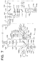
- Fig. 7 is a schematic view showing the major components of an optical system of the laser treatment apparatus in the third embodiment.
- a treatment laser source 109 is constructed of an ion laser tube 110, a first total reflection mirror 110a, a second total reflection mirror 110b, and an output mirror 111.
- the laser tube 110 is a krypton laser (Kr) which oscillates red light with a wavelength of 647.1 nm, yellow light with a wavelength of 568.2 nm, and green light with wavelengths of 530.9 nm and 520.8 nm.
- the first total reflection mirror 110a has the property of reflecting yellow light and green light, and it is fixedly disposed on the laser optical axis.
- the second reflection mirror 110b has the property of reflecting red light, and it is disposed insertably onto the optical path.
- the output mirror 111 has the transmission rate of 1% to 3% for any of red light, yellow light, and green light with respective wavelength regions. Accordingly, when the second mirror 110b is positioned on the optical path, thus constructing a resonator in cooperation with the output mirror 111, and the resonator oscillates a red laser light. On the other hand, when the second mirror 110b is retracted from the optical path, the first mirror 110a constructs a resonator in cooperation with the output mirror 111, and the resonator oscillates an yellow laser light beam and a green laser light.
- Numeral 114 is a beam splitter for allowing a large part of the laser beam from the laser source 109 to pass, while reflecting the other part of the laser beam.
- the laser beam reflected by the beam splitter 114 passes through a diffusion plate 115 and enters an output sensor 116.
- This sensor 116 detects the output energy of the laser beam emitted from the laser source 109.
- Numeral 112 is a wavelength selection filter which selectively allows the green laser beam to pass.
- Numeral 113 is a wavelength selection filter which selectively the yellow laser beam to pass. Inserting either of the filter 112 or 113 onto the optical path furthermore makes it possible to chose any one of the laser beam with the yellow wavelength and the laser beam with the green wavelength both which are simultaneously emitted from the laser source 109.
- the wavelength selection filters 112 and 113 are inserted onto the optical path when filter driving devices 162 and 163 shown in Fig. 8 are operated. The inserted state of the filters 112 and 113 is checked by filter sensors 112a and 113a respectively.
- a first safety shatter 117 is so arranged as to be retracted from the optical path by operation of a driving device 140 in response to the command signal of treatment laser irradiation, thereby to allow the laser beam to pass, while to be inserted onto the optical path in a predetermined case, e.g., when abnormal conditions are encountered.
- the open and closed state of the first safety shatter 117 is detected by a shatter sensor 117a.
- Numeral 118 is a dichroic mirror.
- the red aiming laser beam emitted from a semiconductor laser 119 is made coaxial with the treatment laser beam through a collimator lens 120.
- a second safety shatter 121 is inserted onto the optical path while the semiconductor laser 119 does not emit the aiming laser beam.
- the open and closed state of the second shatter 121 is detected by a shatter sensor 121a.
- Disposed on the optical path is a condensing lens 122 that condenses the treatment laser beam and the aiming laser beam at an incident end 102a of an optical fiber 102 to cause the laser beam to enter therein.
- the laser beam is delivered through the optical fiber 102 to a laser irradiation section 105.
- the laser beam then passes through a relay lens 124, a zooming lens 125 which is movable along the optical axis to vary a spot size of the laser beam, and an objective lens 126, and the laser beam is reflected by a total reflection mirror 127 toward the patient's eye E.
- the laser beam then irradiates the eye E through a contact lens 128 set on the eye E.
- the total reflection mirror 127 has the property of reflecting the treatment laser beam emitted from the laser source 109 and a part of the aiming laser beam emitted from the semiconductor laser 119, while allowing the observation light to pass.
- An illumination light from an illumination light source 130 of an illumination section 106 is made into parallel luminous flux by a condenser lens 131 and illuminates a slit 132. After passed through the slit 132, the illumination light passes through a projection lens 133, and the light is reflected by split mirrors 135a and 135b and illuminates the patient's eye E through the contact lens 128.
- Numeral 134 is a correcting lens 134 for correcting a length of the optical path of the illumination light reflected by the splitting mirrors 135a and 135b.
- the light quantity of the illumination light source 130 can be adjusted consecutively and changeably by operation of a change switch 161.
- a microscope section 104a is provided with an objective lens 141 which is in common used between the right and left observation optical paths, an image forming lens 142, an erect prism 143, a field stop 144, and an eyepiece 146, the elements from 142 to 146 being disposed in each of the right and left optical paths.
- an operator's safety filter 145 is inserted onto the optical path between the lenses 141 and 142.
- a display section 150 is provided with a double-sided mirror 151 having both sides made of total reflection mirrors, disposed obliquely with respect to one of the observation optical paths and between the safety filter 145 and the image forming lens 142.
- the double-sided mirror 151 is so constructed as not to much shade an observation light.
- an LED 152a which emits red light
- an LED 152b which emits yellow light
- an LED 152c which emits green light
- a stop 153 positioned in conjugation with the field stop 144
- a collimator lens 154 is provided above the mirror 151.
- the stop 153 is formed with three apertures arranged in correspondence with the three LEDs 152a, 152b, and 152c such that the display luminous flux from the LEDs 152a, 152b, and 152c may be observed respectively out of the center of the observation visual field (see Fig. 9).
- the form of the apertures is made quadrilateral to avoid the same form as a circular form of luminous flux of the aiming light.
- a light sensor 155 is disposed below the double-sided mirror 151. A part of the observation light reflected by the patient's eye E is reflected by the mirror 151, and the light sensor 155 detects the light quantity of the reflected light.
- FIG. 8 An operator makes a patient sit still in a predetermined position, and operates the joystick 5 to move the slit lamp delivery 104 so as to adjust a slit light from the illumination part 106 onto the eye E. After adjustment of the light quantity of the slit light and the focus, the operator sets a contact lens 128 on the patient's eye E and observes the affected part of eye E through the microscope section 104a. Prior to laser irradiation, the operator operates switches on a control box 103 to set or select various conditions for laser irradiation such as laser beam's wavelength and output energy, and coagulation time, etc..
- the wavelength of the laser beam to be irradiated is selected from wavelength regions of red, yellow, yellowish green, and green to meet the treatment purpose.
- a control section 160 drives the mirror driving device 161 for causing the wavelength selection mirror 110b to be inserted onto or retracted from the optical path, and also drives the filter driving devices 162 and 163 to cause the wavelength selection filters 112 and 113 respectively to be inserted onto or retracted from the optical path, thereby setting a required optical system to obtain a laser beam with a selected wavelength.
- the control section 160 controls the LEDs 152a, 152b, and 152c in the following manner. If a red laser beam is selected, only the LED 152a is turned on. If an yellow laser beam is selected, only the LED 152b is turned on. If a green laser beam is selected, only the LED 152c is turned on. If an yellowish green laser beam is selected, the LED 152b for yellow light and the LED 152c for green light are turned on at the same time.
- Fig. 9 is an illustration of a state of a visual field viewed through the microscope section 104a of the third embodiment.
- Numeral 180 indicates a diameter of the visual field viewed through the microscope section 104a.
- Numeral 181 indicates an fundus image of the patient's eye E.
- a color information area 181 is projected with color when the LED 152a is turned on.
- a color information area 182 is projected with color when the LED 152b is turned on.
- a color information area 183 is projected with color when the LED 152c is turned on.
- those color information areas 182, 183, and 184 are not projected with color. This can avoid unnecessary shading of the visual field.
- the light quantity of the LED's light to display the areas 182, 182, and 184 is determined based on the light quantity of the fundus-reflected light from the patient's eye E, the reflected light quantity being detected by the light sensor 155.
- the illumination light from the illumination section 106 illuminates the eye fundus, and the fundus-reflected light passes through the total reflection mirror 127 and the objective lens 141, and the light is reflected by the double-sided mirror 151 toward the light sensor 151.
- This sensor 151 thus detects the light quantity of the reflected light.
- a light quantity regulation part 164 regulates the emission light quantity of the LEDs 152a, 152b, and 152c which are turned on in response to the detection signal output from the light sensor 155.
- the emission light quantity of the LEDs 152a-152c is increased when a detected light quantity is large, while it is lowered when the detected light quantity is small.
- the change in the emission light quantity is controlled linearly or in multiple steps by the function empirically found with respect to the variation in light quantity of the reflected light.
- the light quantity of the color information is immediately changed, for example, even when the illumination light quantity is changed by the change switch 161 in order to make easy to observe the affected part.
- the light quantity of the LEDs 152a, 152b, and 152c is retained in a previously determined constant relation to the light quantity of the reflected light from the eye fundus, thereby enabling the operator to satisfactorily observe both the information displayed within the visual field and the part to be observed (the eye fundus).
Landscapes
- Health & Medical Sciences (AREA)
- Ophthalmology & Optometry (AREA)
- Heart & Thoracic Surgery (AREA)
- Vascular Medicine (AREA)
- Optics & Photonics (AREA)
- Surgery (AREA)
- Engineering & Computer Science (AREA)
- Biomedical Technology (AREA)
- Physics & Mathematics (AREA)
- Nuclear Medicine, Radiotherapy & Molecular Imaging (AREA)
- Life Sciences & Earth Sciences (AREA)
- Animal Behavior & Ethology (AREA)
- General Health & Medical Sciences (AREA)
- Public Health (AREA)
- Veterinary Medicine (AREA)
- Laser Surgery Devices (AREA)
Applications Claiming Priority (4)
| Application Number | Priority Date | Filing Date | Title |
|---|---|---|---|
| JP10125446A JPH11276514A (ja) | 1998-03-31 | 1998-03-31 | レーザ治療装置 |
| JP12544898A JP3939021B2 (ja) | 1998-03-31 | 1998-03-31 | レーザ治療装置 |
| JP12544698 | 1998-03-31 | ||
| JP12544898 | 1998-03-31 |
Publications (3)
| Publication Number | Publication Date |
|---|---|
| EP0947183A2 true EP0947183A2 (de) | 1999-10-06 |
| EP0947183A3 EP0947183A3 (de) | 1999-12-08 |
| EP0947183B1 EP0947183B1 (de) | 2003-05-28 |
Family
ID=26461889
Family Applications (1)
| Application Number | Title | Priority Date | Filing Date |
|---|---|---|---|
| EP99105503A Expired - Lifetime EP0947183B1 (de) | 1998-03-31 | 1999-03-17 | Laserbehandlungsvorrichtung |
Country Status (3)
| Country | Link |
|---|---|
| US (1) | US6235014B1 (de) |
| EP (1) | EP0947183B1 (de) |
| DE (1) | DE69908232T2 (de) |
Cited By (3)
| Publication number | Priority date | Publication date | Assignee | Title |
|---|---|---|---|---|
| EP1363546A4 (de) * | 2001-02-02 | 2004-06-16 | Gregg S Homer | Methode zur veränderung des irispigments |
| EP1377243A4 (de) * | 2001-04-12 | 2005-05-04 | Ellex Medical Pty Ltd | Ophthalmisches lasersystem |
| EP1253893A4 (de) * | 2000-02-03 | 2005-12-28 | Gregg S Homer | Verfahren zum verändern der irispigmentierung |
Families Citing this family (13)
| Publication number | Priority date | Publication date | Assignee | Title |
|---|---|---|---|---|
| US20040267246A1 (en) * | 2002-02-01 | 2004-12-30 | Nidek Co., Ltd. | Laser treatment apparatus |
| DE10305117A1 (de) * | 2003-02-07 | 2004-08-19 | Leica Microsystems Wetzlar Gmbh | Einrichtung und Software zum Steuern von Funktionen eines Mikroskopsystems |
| DE10361158B4 (de) * | 2003-12-22 | 2007-05-16 | Leica Microsystems | Einrichtung und Verfahren zur Konfiguration eines Mikroskops |
| JP2005221561A (ja) * | 2004-02-03 | 2005-08-18 | Olympus Corp | 顕微鏡 |
| WO2006036176A1 (en) * | 2004-09-24 | 2006-04-06 | Light Sciences Corporation | Extended treatment of tumors through vessel occlusion with light activated drugs |
| US20060084951A1 (en) * | 2004-10-05 | 2006-04-20 | Heacock Gregory L | Low energy of excitation PDT compounds for treatment of ocular disease |
| DE102005013949A1 (de) | 2005-03-26 | 2006-09-28 | Carl Zeiss Meditec Ag | Scanvorrichtung |
| JP4492874B2 (ja) * | 2005-03-31 | 2010-06-30 | 株式会社ニデック | 眼科用レーザ治療装置 |
| JP4970068B2 (ja) * | 2007-01-30 | 2012-07-04 | 株式会社ニデック | 眼科用レーザ治療装置 |
| EP3191040B1 (de) | 2014-09-09 | 2020-07-15 | Lumithera, Inc. | Vorrichtungen für mehrwellenlängenphototherapie für nichtinvasive behandlung von verletztem oder erkranktem gewebe |
| NZ773822A (en) | 2015-03-16 | 2022-07-29 | Magic Leap Inc | Methods and systems for diagnosing and treating health ailments |
| EP3440497B1 (de) | 2016-04-08 | 2023-08-16 | Magic Leap, Inc. | Systeme der erweiterten realität und verfahren mit linsenelementen mit veränderlicher brennweite |
| IL307602A (en) | 2017-02-23 | 2023-12-01 | Magic Leap Inc | Variable focus virtual imagers based on polarization conversion |
Family Cites Families (22)
| Publication number | Priority date | Publication date | Assignee | Title |
|---|---|---|---|---|
| US4530011A (en) * | 1981-06-19 | 1985-07-16 | Loge/Dunn Instruments, Inc. | Apparatus for maintaining of a cathode ray tube image within the light acceptance range of a photographic film |
| US4597649A (en) | 1983-10-28 | 1986-07-01 | American Hospital Supply Corporation | Information display apparatus for ophthalmic slit lamps |
| US4682595A (en) * | 1985-03-25 | 1987-07-28 | Carl-Zeiss-Stiftung | Illuminance dosage device |
| AU606315B2 (en) * | 1985-09-12 | 1991-02-07 | Summit Technology, Inc. | Surface erosion using lasers |
| US4702576A (en) * | 1985-09-27 | 1987-10-27 | Cambridge Instruments Inc. | Ocular scattering analyzer |
| US5098426A (en) * | 1989-02-06 | 1992-03-24 | Phoenix Laser Systems, Inc. | Method and apparatus for precision laser surgery |
| US5196006A (en) * | 1989-04-25 | 1993-03-23 | Summit Technology, Inc. | Method and apparatus for excision endpoint control |
| JP2933945B2 (ja) * | 1989-05-29 | 1999-08-16 | 株式会社トプコン | レーザ治療装置 |
| JP2885290B2 (ja) | 1989-07-14 | 1999-04-19 | 株式会社トプコン | レーザ装置 |
| JP3206923B2 (ja) * | 1991-01-30 | 2001-09-10 | 株式会社ニデック | 眼科用レーザ手術装置 |
| JP3125360B2 (ja) * | 1991-09-17 | 2001-01-15 | 株式会社ニコン | 位置検出装置及び投影露光装置 |
| JP2965101B2 (ja) * | 1992-07-31 | 1999-10-18 | 株式会社ニデック | 眼科装置 |
| JP2907656B2 (ja) * | 1992-08-31 | 1999-06-21 | 株式会社ニデック | レ−ザ手術装置 |
| JPH06142130A (ja) * | 1992-11-07 | 1994-05-24 | Nidek Co Ltd | 眼科用レ−ザ手術装置 |
| JPH06178761A (ja) * | 1992-12-10 | 1994-06-28 | Nikon Corp | フィルタ種類のファインダー内表示装置を有する眼科装置 |
| IL108672A (en) * | 1993-02-19 | 1997-07-13 | Phoenix Laser Systems | System for detecting, measuring and compensating for lateral movements of a target |
| US5395356A (en) * | 1993-06-04 | 1995-03-07 | Summit Technology, Inc. | Correction of presbyopia by photorefractive keratectomy |
| ES2180597T4 (es) * | 1994-08-18 | 2003-07-01 | Zeiss Carl | Aparato quirurgico asistido por tomografia de coherencia optica. |
| US5620436A (en) * | 1994-09-22 | 1997-04-15 | Chiron Technolas Gmbh Ophthalmologische Systeme | Method and apparatus for providing precise location of points on the eye |
| US5480396A (en) * | 1994-12-09 | 1996-01-02 | Simon; Gabriel | Laser beam ophthalmological surgery method and apparatus |
| JP3675876B2 (ja) * | 1995-02-28 | 2005-07-27 | 株式会社ニデック | レ−ザ治療装置 |
| JPH0937196A (ja) | 1995-07-17 | 1997-02-07 | Sony Corp | 液晶表示装置 |
-
1999
- 1999-03-17 EP EP99105503A patent/EP0947183B1/de not_active Expired - Lifetime
- 1999-03-17 DE DE69908232T patent/DE69908232T2/de not_active Expired - Fee Related
- 1999-03-30 US US09/281,273 patent/US6235014B1/en not_active Expired - Fee Related
Non-Patent Citations (1)
| Title |
|---|
| None |
Cited By (4)
| Publication number | Priority date | Publication date | Assignee | Title |
|---|---|---|---|---|
| EP1253893A4 (de) * | 2000-02-03 | 2005-12-28 | Gregg S Homer | Verfahren zum verändern der irispigmentierung |
| EP1363546A4 (de) * | 2001-02-02 | 2004-06-16 | Gregg S Homer | Methode zur veränderung des irispigments |
| EP1377243A4 (de) * | 2001-04-12 | 2005-05-04 | Ellex Medical Pty Ltd | Ophthalmisches lasersystem |
| US7033346B2 (en) | 2001-04-12 | 2006-04-25 | Ellex Medical Pty. Ltd. | Ophthalmic laser system |
Also Published As
| Publication number | Publication date |
|---|---|
| EP0947183A3 (de) | 1999-12-08 |
| EP0947183B1 (de) | 2003-05-28 |
| DE69908232T2 (de) | 2004-04-01 |
| DE69908232D1 (de) | 2003-07-03 |
| US6235014B1 (en) | 2001-05-22 |
Similar Documents
| Publication | Publication Date | Title |
|---|---|---|
| EP0947183B1 (de) | Laserbehandlungsvorrichtung | |
| EP0882438B1 (de) | Laserbehandlungsvorrichtung | |
| US6932807B1 (en) | Laser treatment apparatus | |
| EP1114608B1 (de) | Augenbeobachtungsgerät mit einzeln angesteuerten Leuchtdioden zur farbkorrigierten Beleuchtung | |
| US7229435B2 (en) | Ophthalmic laser treatment apparatus | |
| US8382743B2 (en) | Ophthalmic laser treatment apparatus | |
| US6325793B1 (en) | Laser treatment apparatus | |
| US6530918B1 (en) | Laser treatment apparatus | |
| US20080188838A1 (en) | Ophthalmic laser treatment apparatus | |
| US6322554B1 (en) | Laser treatment apparatus | |
| US6652511B1 (en) | Laser treatment apparatus | |
| JP6531508B2 (ja) | レーザ治療装置 | |
| JP2020081792A (ja) | 眼科用レーザ治療装置 | |
| US6699238B1 (en) | Laser operating system | |
| JP3953643B2 (ja) | レーザ治療装置 | |
| US6383178B1 (en) | Laser treatment apparatus | |
| JP6813053B2 (ja) | レーザ治療装置 | |
| JP2001258852A (ja) | 眼底撮影装置 | |
| JP3939021B2 (ja) | レーザ治療装置 | |
| JP3842969B2 (ja) | レーザ治療装置 | |
| JPH11276514A (ja) | レーザ治療装置 | |
| JP3199779B2 (ja) | 眼内光凝固装置 | |
| JP2006101940A (ja) | 眼科用レーザ治療装置 | |
| JP2001161739A (ja) | レーザ治療装置 | |
| JP2000175955A (ja) | レーザ治療装置 |
Legal Events
| Date | Code | Title | Description |
|---|---|---|---|
| PUAI | Public reference made under article 153(3) epc to a published international application that has entered the european phase |
Free format text: ORIGINAL CODE: 0009012 |
|
| AK | Designated contracting states |
Kind code of ref document: A2 Designated state(s): DE FR GB |
|
| AX | Request for extension of the european patent |
Free format text: AL;LT;LV;MK;RO;SI |
|
| PUAL | Search report despatched |
Free format text: ORIGINAL CODE: 0009013 |
|
| AK | Designated contracting states |
Kind code of ref document: A3 Designated state(s): AT BE CH CY DE DK ES FI FR GB GR IE IT LI LU MC NL PT SE |
|
| AX | Request for extension of the european patent |
Free format text: AL;LT;LV;MK;RO;SI |
|
| 17P | Request for examination filed |
Effective date: 20000504 |
|
| AKX | Designation fees paid |
Free format text: DE FR GB |
|
| 17Q | First examination report despatched |
Effective date: 20000814 |
|
| GRAG | Despatch of communication of intention to grant |
Free format text: ORIGINAL CODE: EPIDOS AGRA |
|
| GRAG | Despatch of communication of intention to grant |
Free format text: ORIGINAL CODE: EPIDOS AGRA |
|
| GRAH | Despatch of communication of intention to grant a patent |
Free format text: ORIGINAL CODE: EPIDOS IGRA |
|
| GRAH | Despatch of communication of intention to grant a patent |
Free format text: ORIGINAL CODE: EPIDOS IGRA |
|
| GRAA | (expected) grant |
Free format text: ORIGINAL CODE: 0009210 |
|
| AK | Designated contracting states |
Designated state(s): DE FR GB |
|
| REG | Reference to a national code |
Ref country code: GB Ref legal event code: FG4D |
|
| REF | Corresponds to: |
Ref document number: 69908232 Country of ref document: DE Date of ref document: 20030703 Kind code of ref document: P |
|
| ET | Fr: translation filed | ||
| PGFP | Annual fee paid to national office [announced via postgrant information from national office to epo] |
Ref country code: FR Payment date: 20040309 Year of fee payment: 6 |
|
| PGFP | Annual fee paid to national office [announced via postgrant information from national office to epo] |
Ref country code: GB Payment date: 20040317 Year of fee payment: 6 |
|
| PGFP | Annual fee paid to national office [announced via postgrant information from national office to epo] |
Ref country code: DE Payment date: 20040325 Year of fee payment: 6 |
|
| PLBE | No opposition filed within time limit |
Free format text: ORIGINAL CODE: 0009261 |
|
| STAA | Information on the status of an ep patent application or granted ep patent |
Free format text: STATUS: NO OPPOSITION FILED WITHIN TIME LIMIT |
|
| 26N | No opposition filed |
Effective date: 20040302 |
|
| PG25 | Lapsed in a contracting state [announced via postgrant information from national office to epo] |
Ref country code: GB Free format text: LAPSE BECAUSE OF NON-PAYMENT OF DUE FEES Effective date: 20050317 |
|
| PG25 | Lapsed in a contracting state [announced via postgrant information from national office to epo] |
Ref country code: DE Free format text: LAPSE BECAUSE OF NON-PAYMENT OF DUE FEES Effective date: 20051001 |
|
| GBPC | Gb: european patent ceased through non-payment of renewal fee |
Effective date: 20050317 |
|
| PG25 | Lapsed in a contracting state [announced via postgrant information from national office to epo] |
Ref country code: FR Free format text: LAPSE BECAUSE OF NON-PAYMENT OF DUE FEES Effective date: 20051130 |
|
| REG | Reference to a national code |
Ref country code: FR Ref legal event code: ST Effective date: 20051130 |