EP0947273A2 - Plattensäge - Google Patents
Plattensäge Download PDFInfo
- Publication number
- EP0947273A2 EP0947273A2 EP99830154A EP99830154A EP0947273A2 EP 0947273 A2 EP0947273 A2 EP 0947273A2 EP 99830154 A EP99830154 A EP 99830154A EP 99830154 A EP99830154 A EP 99830154A EP 0947273 A2 EP0947273 A2 EP 0947273A2
- Authority
- EP
- European Patent Office
- Prior art keywords
- stack
- blade
- panels
- carriage
- saw
- Prior art date
- Legal status (The legal status is an assumption and is not a legal conclusion. Google has not performed a legal analysis and makes no representation as to the accuracy of the status listed.)
- Granted
Links
Images


Classifications
-
- B—PERFORMING OPERATIONS; TRANSPORTING
- B23—MACHINE TOOLS; METAL-WORKING NOT OTHERWISE PROVIDED FOR
- B23D—PLANING; SLOTTING; SHEARING; BROACHING; SAWING; FILING; SCRAPING; LIKE OPERATIONS FOR WORKING METAL BY REMOVING MATERIAL, NOT OTHERWISE PROVIDED FOR
- B23D45/00—Sawing machines or sawing devices with circular saw blades or with friction saw discs
- B23D45/10—Sawing machines or sawing devices with circular saw blades or with friction saw discs with a plurality of circular saw blades
- B23D45/105—Sawing machines or sawing devices with circular saw blades or with friction saw discs with a plurality of circular saw blades operating within the same plane
-
- B—PERFORMING OPERATIONS; TRANSPORTING
- B27—WORKING OR PRESERVING WOOD OR SIMILAR MATERIAL; NAILING OR STAPLING MACHINES IN GENERAL
- B27G—ACCESSORY MACHINES OR APPARATUS FOR WORKING WOOD OR SIMILAR MATERIALS; TOOLS FOR WORKING WOOD OR SIMILAR MATERIALS; SAFETY DEVICES FOR WOOD WORKING MACHINES OR TOOLS
- B27G19/00—Safety guards or devices specially adapted for wood saws; Auxiliary devices facilitating proper operation of wood saws
- B27G19/10—Measures preventing splintering of sawn portions of wood
-
- Y—GENERAL TAGGING OF NEW TECHNOLOGICAL DEVELOPMENTS; GENERAL TAGGING OF CROSS-SECTIONAL TECHNOLOGIES SPANNING OVER SEVERAL SECTIONS OF THE IPC; TECHNICAL SUBJECTS COVERED BY FORMER USPC CROSS-REFERENCE ART COLLECTIONS [XRACs] AND DIGESTS
- Y10—TECHNICAL SUBJECTS COVERED BY FORMER USPC
- Y10T—TECHNICAL SUBJECTS COVERED BY FORMER US CLASSIFICATION
- Y10T83/00—Cutting
- Y10T83/02—Other than completely through work thickness
- Y10T83/0207—Other than completely through work thickness or through work presented
- Y10T83/0215—Including use of rotary scoring blade
-
- Y—GENERAL TAGGING OF NEW TECHNOLOGICAL DEVELOPMENTS; GENERAL TAGGING OF CROSS-SECTIONAL TECHNOLOGIES SPANNING OVER SEVERAL SECTIONS OF THE IPC; TECHNICAL SUBJECTS COVERED BY FORMER USPC CROSS-REFERENCE ART COLLECTIONS [XRACs] AND DIGESTS
- Y10—TECHNICAL SUBJECTS COVERED BY FORMER USPC
- Y10T—TECHNICAL SUBJECTS COVERED BY FORMER US CLASSIFICATION
- Y10T83/00—Cutting
- Y10T83/02—Other than completely through work thickness
- Y10T83/0207—Other than completely through work thickness or through work presented
- Y10T83/0215—Including use of rotary scoring blade
- Y10T83/0222—Plural independent rotary scoring blades
-
- Y—GENERAL TAGGING OF NEW TECHNOLOGICAL DEVELOPMENTS; GENERAL TAGGING OF CROSS-SECTIONAL TECHNOLOGIES SPANNING OVER SEVERAL SECTIONS OF THE IPC; TECHNICAL SUBJECTS COVERED BY FORMER USPC CROSS-REFERENCE ART COLLECTIONS [XRACs] AND DIGESTS
- Y10—TECHNICAL SUBJECTS COVERED BY FORMER USPC
- Y10T—TECHNICAL SUBJECTS COVERED BY FORMER US CLASSIFICATION
- Y10T83/00—Cutting
- Y10T83/02—Other than completely through work thickness
- Y10T83/0333—Scoring
- Y10T83/0363—Plural independent scoring blades
- Y10T83/037—Rotary scoring blades
- Y10T83/0378—On opposite sides of work
-
- Y—GENERAL TAGGING OF NEW TECHNOLOGICAL DEVELOPMENTS; GENERAL TAGGING OF CROSS-SECTIONAL TECHNOLOGIES SPANNING OVER SEVERAL SECTIONS OF THE IPC; TECHNICAL SUBJECTS COVERED BY FORMER USPC CROSS-REFERENCE ART COLLECTIONS [XRACs] AND DIGESTS
- Y10—TECHNICAL SUBJECTS COVERED BY FORMER USPC
- Y10T—TECHNICAL SUBJECTS COVERED BY FORMER US CLASSIFICATION
- Y10T83/00—Cutting
- Y10T83/768—Rotatable disc tool pair or tool and carrier
- Y10T83/7755—Carrier for rotatable tool movable during cutting
- Y10T83/7763—Tool carrier reciprocable rectilinearly
Definitions
- the present invention relates to a device for sawing panels, particularly wooden panels, on panel sawing machines.
- Panel sawing machines in their minimum standard configurations, basically comprise: a horizontal table to support the stacks of panels to be cut; a gripper and handling unit designed to pick up the stack of panels at one end and feed it along a horizontal axis X towards the end of the table where there is a pressing device which holds down one end of the panel stack.
- a motor-driven carriage which mounts a circular saw and, in front of the latter, a scoring saw. The carriage moves in both directions along an axis Y transversal to the panel feed axis X, so as to allow the stack of panels to be scored on the surface and then cut through in the area where it is being held by the hold-down device.
- the scoring saw used in combination with the saw is designed to make only a shallow cut in the surface of the panel (usually the covering layer) in a direction such as to prevent surface splintering.
- the higher production capacities of panel processing lines made possible by continuing technological improvements have greatly increased the demand for larger and larger quantities of panels cut to size to feed the panel processing lines. This demand has been met by simply using saw blades with larger and larger diameters so as to enable higher and higher stacks of panels to be cut.
- the aim of the present invention is to overcome the above mentioned disadvantages by providing a panel sawing device for panel sawing machines that is at once compact and fast, offers excellent cutting precision for high stacks of panels, and whose overall structure occupies a minimum of space.
- a panel sawing machine 2 in a basic, standard configuration comprises the following parts: a horizontal table 3, supporting a tall stack 1 of panels having a preset height S; a gripper and handling unit 4 designed to pick up the stack 1 of panels and feed it on the table 3 along a horizontal axis X towards a part of the table 3 where there are means 5 for pressing down on a portion of the stack 1 of panels and which can move vertically in both directions.
- the gripper and handling unit 4 which is of a known type, consists basically of a crossbeam 4t that moves along the axis X and mounts two or more grippers 4p designed to grip the stack 1;
- the cutting means 6 consist of a first carriage 8 that mounts a circular saw blade 9, with related drive motor 9m, and a circular scoring saw 10 for the stack 1, located upstream of the blade 9 relative to the cutting direction V1.
- the cutting means 6 comprise a second carriage 11, mounting a second circular saw blade 12, with related drive motor 12m, and a second circular scoring saw 13 located opposite the first carriage 8 on the other side of the stack 1 of panels.
- the second carriage 11 also moves in the two cutting and return directions V1 and V2, along the transversal axis Y, in synchrony with the first carriage 8, in such a way as to make a second cut, to a depth S2, that substantially coincides with the first cut in a vertical plane labelled PV: in this way (as clearly shown in Figure 7) a complete cut is made right through the stack 1 of panels.
- the first carriage 8, which we shall call “lower” carriage, is mounted below the table 3, while the second carriage 11, which we shall call “upper” carriage, is located above the free surface SL of the stack 1 of panels.
- the second carriage 11 can be driven along a vertical axis Z, that is, adjusted in height, by related means 14 according to the height S of the stack 1 of panels in such a way that its end position is always near the free surface SL of the stack.
- the first, lower blade 9 can make a cut to a depth S1, starting from the base or lower surface SB of the stack 1 of panels through at least half the height S of the stack 1 of panels.
- the first blade 9 cuts the stack 1 of panels starting from the base or lower surface SB to a depth S1 that is slightly greater than the stack height S.
- the first and second saw blades 9 and 12 may be mounted in such a way that their axes of rotation 9x and 12x are offset relative to a reference axis Z so that the two blades do not interfere with each other.
- the second blade 12 is located upstream of the first blade 9 relative to the cutting direction V1, that is to say, it follows the first blade 9 and comes into contact with the stack 1 of panels after the first blade 9.
- the distance D2 between the second blade 12 and the corresponding second scoring saw 13 is greater than the distance D1 between the first blade 9 and the corresponding first scoring saw 10: this difference is shown clearly in Figure 5 (which illustrates a preferred embodiment without restricting the scope of the invention), where the first and second scoring saws are exactly over each other on opposite sides of the stack 1, corresponding to the surfaces SL and SB of the stack 1.
- the axes 10x and 13x lie on the same reference axis Z'.
- the first blade 9 and the first scoring saw 10 turn in directions labelled V9 and V10 in Figure 5, which are opposite to the directions V12 and V13 of the second blade 12 and the second scoring saw 13.
- the second, upper carriage 11, consisting (see Figure 2) of a plate 60 which mounts the second blade 12, the second scoring saw 13 and the drive motor 12m of the blade 12, may be connected to, and may move together with, the pressing means 5 of the stack 1 of panels, the latter being located in the space between the two hold-downs 5p and 5p', so as to make use of the cylinders 5c that drive the hold-downs themselves (and constituting the above mentioned drive means 14).
- the second carriage 11 may be adjusted along the vertical axis Z independently of the pressing means 5.
- the second carriage 11 consists of the vertical plate 60, divided into two parts 60 and 61 connected to each other.
- the first part 60 is fixed and is connected to the saw blade drive means 7, while the second part 61 mounts the blade 12, the corresponding scoring saw 13 and the drive motor 12m of the blade 12, and can slide relative to the first part 60, being driven in both directions along the vertical axis Z by one or more cylinders 62 (which in practice form the above mentioned drive means 14) acting on said second part 61 of the second carriage 11 and connected to a frame that is attached to the other part 60 of the second carriage 11.
- cylinders 62 which in practice form the above mentioned drive means 14
- the second carriage 11 moves up and down to adjust to the different heights of the stack 1 of panels and, to do this, is equipped with detector means 15, located near the second scoring saw 13 and designed to enable the second scoring saw to be correctly positioned on the free surface SL of the stack 1 of panels.
- the detector means 15, see Figure 6, may consist of idle rollers 16 and 16' which come into contact with the free surface SL and which are keyed to a shaft 17 that mounts the second scoring saw 13 in such a way that they can rotate and are located on both sides of the second scoring saw.
- the detector rollers 16 and 16' have diameters D16 and D16' that are slightly smaller than the diameter D13 of the second scoring saw 13.
- the difference ⁇ between the radius of the rollers and the radius of the scoring saw is equivalent to the depth of the score made by the second scoring saw 13 in the free surface SL of the stack 1.
- the ends of the hold-down elements 5p and 5p' of the pressing means 5 are used to directly reference the second scoring saw 13 and thus perform the function of the detectors 16 and 16'.
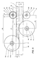
- FIGS 3 and 4 show two different embodiments of the units that drive the carriages 8 and 11.
- first and second carriages 8 and 11 are connected to respective branches of corresponding drive chains or belts 18 and 19, which are looped around respective first and second pairs of pulleys 20, 21 and 22, 23 which drive them in the two directions V1 and V2.
- One pulley 21 and 23 of each carriage 8 and 11 is kinematically connected to the other by a third, shared chain or belt 24 which enables both carriages 8 and 11 to be driven in a synchronized fashion by a single motor 7m.
- the third chain 24 has a transfer roller 30 and a dandy roller 31 to keep the third chain 24 properly tensioned as it turns during adjustments in height (see arrow F in Figure 3) of the second carriage 11.
- the drive unit of the two carriages 8 and 11 is similar to that described above but differs mainly in that there are two independent motors 7m and 25m connected to the respective pulleys 21 and 23 of the two carriages 8 and 11.
- the drive motion to the two chains or belts 18 and 19 is synchronized by a control unit 26 (illustrated as a block) which may consist of a software or numerical control unit located on the panel sawing machine.
- a device made in this way achieves the above mentioned aims thanks to its extremely simple structure for panel sawing machines required to cut tall stacks of panels.
- the device has numerous advantages stemming from the fact that it allows small blades to be used. That means the blades are less likely to bend and can therefore be thinner while maintaining a sharp cutting edge for longer periods.
- the two saw blades each with a corresponding scoring saw, designed to cut into the panels from both sides of the stack produce less waste and greatly reduces splintering on the free surface of the stack.
Landscapes
- Life Sciences & Earth Sciences (AREA)
- Engineering & Computer Science (AREA)
- Mechanical Engineering (AREA)
- Wood Science & Technology (AREA)
- Forests & Forestry (AREA)
- Sawing (AREA)
- Shearing Machines (AREA)
- Devices For Post-Treatments, Processing, Supply, Discharge, And Other Processes (AREA)
- Glass Compositions (AREA)
- Gas-Filled Discharge Tubes (AREA)
- Particle Formation And Scattering Control In Inkjet Printers (AREA)
Applications Claiming Priority (2)
| Application Number | Priority Date | Filing Date | Title |
|---|---|---|---|
| IT98BO000208A IT1299944B1 (it) | 1998-03-31 | 1998-03-31 | Dispositivo per il taglio di pannelli. |
| ITBO980208 | 1998-03-31 |
Publications (3)
| Publication Number | Publication Date |
|---|---|
| EP0947273A2 true EP0947273A2 (de) | 1999-10-06 |
| EP0947273A3 EP0947273A3 (de) | 2001-02-28 |
| EP0947273B1 EP0947273B1 (de) | 2005-06-08 |
Family
ID=11343079
Family Applications (1)
| Application Number | Title | Priority Date | Filing Date |
|---|---|---|---|
| EP99830154A Expired - Lifetime EP0947273B1 (de) | 1998-03-31 | 1999-03-19 | Plattensäge |
Country Status (6)
| Country | Link |
|---|---|
| US (1) | US6178864B1 (de) |
| EP (1) | EP0947273B1 (de) |
| AT (1) | ATE297283T1 (de) |
| CA (1) | CA2266875C (de) |
| DE (1) | DE69925662T2 (de) |
| IT (1) | IT1299944B1 (de) |
Cited By (4)
| Publication number | Priority date | Publication date | Assignee | Title |
|---|---|---|---|---|
| NL1019102C2 (nl) * | 2001-10-03 | 2003-04-04 | Luxwood Systems B V | Werkwijze en inrichting voor het vervaardigen van vloerdelen, alsmede een vloerdeel. |
| WO2006064369A1 (en) * | 2004-12-16 | 2006-06-22 | Giben International S.P.A. | A panel cutting device |
| EP2554312A1 (de) * | 2011-08-05 | 2013-02-06 | SCM Group S.p.A. | Verfahren und Vorrichtung zum Schneiden von Platten |
| CN103753649A (zh) * | 2014-02-27 | 2014-04-30 | 东北林业大学 | 数控往复式双圆锯薄木剖分锯动力传递结构 |
Families Citing this family (5)
| Publication number | Priority date | Publication date | Assignee | Title |
|---|---|---|---|---|
| TW200408061A (en) * | 2002-07-02 | 2004-05-16 | Mitsuboshi Diamond Ind Co Ltd | Substrate slicing system for sealed substrates and the substrate slicing method |
| DE102006012253A1 (de) * | 2006-03-15 | 2007-09-20 | Otto Martin Maschinenbau Gmbh & Co. Kg | Verfahren und Vorrichtung zur Ritztiefensteuerung für Vorritzsägen |
| CN109664372A (zh) * | 2019-02-26 | 2019-04-23 | 上海华鄂工程技术有限公司 | 一种上锯式裁板锯装置 |
| CN110450255A (zh) * | 2019-08-20 | 2019-11-15 | 东莞市众金家具有限公司 | 一种智能家居用板式部件生产线 |
| US11608642B2 (en) * | 2020-02-13 | 2023-03-21 | LVP Stairs LLC | Devices and methods for fitting luxury vinyl plank floorcovering to interior stairs |
Family Cites Families (21)
| Publication number | Priority date | Publication date | Assignee | Title |
|---|---|---|---|---|
| US1691102A (en) * | 1927-05-31 | 1928-11-13 | Ramar Syndicate Inc | Wood-splitting machine |
| GB912673A (en) * | 1960-07-21 | 1962-12-12 | Peter Raymond Deuss | Improvements in or relating to floorboarding tongue cutters and the like |
| FR1413076A (fr) * | 1964-02-13 | 1965-10-08 | Stratex | Dispositif de sciage pour panneaux fabriqués en continu |
| DE1728394C3 (de) * | 1966-07-09 | 1978-05-11 | Gino Pianoro Bologna Benuzzi (Italien) | Tischkreissäge |
| US3583449A (en) * | 1968-10-09 | 1971-06-08 | Masonite Corp | Self-guiding saw blade |
| DE2159427A1 (de) * | 1971-12-01 | 1973-06-07 | Ottokar Cerv | Vorrichtung zur bearbeitung von plattenfoermigen werkstuecken |
| DE2523034C3 (de) * | 1975-05-24 | 1978-05-24 | F. Meyer & Schwabedissen Gmbh & Co Kg, 4900 Herford | Vorrichtung zum automatischen Buntaufteilen einer Platte |
| US4009741A (en) * | 1976-03-23 | 1977-03-01 | E.Z. Mfg. Co. | Woodworking machine |
| US4210052A (en) * | 1977-05-09 | 1980-07-01 | Libbey-Owens-Ford Company | Scoring mechanism |
| US4204445A (en) * | 1977-05-31 | 1980-05-27 | Ppg Industries, Inc. | Scoring device having a referencing carriage |
| US4215613A (en) * | 1978-05-01 | 1980-08-05 | Eric A. Anderson | Slitting apparatus |
| AT364514B (de) * | 1978-11-13 | 1981-10-27 | Lindner Werk Gmbh | Kreissaege |
| US4228711A (en) * | 1979-05-17 | 1980-10-21 | The Fletcher-Terry Company | Self-castering glass cutter and compensating bi-directional head |
| US4300604A (en) * | 1980-05-12 | 1981-11-17 | Zimmerman Edwin H | System to produce wood products from peeler core logs |
| IT1145521B (it) * | 1981-10-20 | 1986-11-05 | Giben Impianti Spa | Dispositivo incisore, particolarmente adatto per le macchine e per gli impianti adibiti alla sezionatura di pannelli di legno e/od in altro materiale |
| DE3403710C1 (de) * | 1984-02-03 | 1985-07-18 | Carl Schmale GmbH & Co KG, 4434 Ochtrup | Vorrichtung zum fortlaufenden Laengstrennen von Gewebebahnen |
| IT208464Z2 (it) * | 1985-05-10 | 1988-05-28 | Giben Impianti Spa | Pressore per macchine sezionatrici di pacchi di pannelli di legno e od altro materiale dotato di due organi di pressatura ad azionamento indipendente |
| IT1186903B (it) * | 1985-07-03 | 1987-12-16 | Giben Impianti Spa | Procedimento per la sezionatura fine di pannelli o pacchi di pannelli in legno o suci derivati specialmente se rivestiti con laminati di nobilitazione e sezionatrice realizzata con tale metodo caratterizzata dall essere priva di incisori |
| DE3716086A1 (de) * | 1987-05-14 | 1988-12-01 | Jenkner Erwin | Vorrichtung zur einstellung von eingriffstiefen eines vorritzsaegeblattes waehrend des vorschubes eines verfahrbaren saegeaggregates |
| AT400826B (de) * | 1994-07-14 | 1996-03-25 | Schelling & Co | Verfahren zum einstellen eines vorritzers gegenüber einem trennsägeblatt und vorrichtung zur durchführung des verfahrens |
| IT1279651B1 (it) * | 1995-10-11 | 1997-12-16 | Selco Srl | Macchina sezionatrice di pezzi. |
-
1998
- 1998-03-31 IT IT98BO000208A patent/IT1299944B1/it active IP Right Grant
-
1999
- 1999-03-19 AT AT99830154T patent/ATE297283T1/de active
- 1999-03-19 DE DE69925662T patent/DE69925662T2/de not_active Expired - Lifetime
- 1999-03-19 US US09/272,409 patent/US6178864B1/en not_active Expired - Fee Related
- 1999-03-19 EP EP99830154A patent/EP0947273B1/de not_active Expired - Lifetime
- 1999-03-25 CA CA002266875A patent/CA2266875C/en not_active Expired - Fee Related
Cited By (5)
| Publication number | Priority date | Publication date | Assignee | Title |
|---|---|---|---|---|
| NL1019102C2 (nl) * | 2001-10-03 | 2003-04-04 | Luxwood Systems B V | Werkwijze en inrichting voor het vervaardigen van vloerdelen, alsmede een vloerdeel. |
| WO2006064369A1 (en) * | 2004-12-16 | 2006-06-22 | Giben International S.P.A. | A panel cutting device |
| EP2554312A1 (de) * | 2011-08-05 | 2013-02-06 | SCM Group S.p.A. | Verfahren und Vorrichtung zum Schneiden von Platten |
| ITMO20110203A1 (it) * | 2011-08-05 | 2013-02-06 | Scm Group Spa | Metodo e apparato per lavorare pannelli |
| CN103753649A (zh) * | 2014-02-27 | 2014-04-30 | 东北林业大学 | 数控往复式双圆锯薄木剖分锯动力传递结构 |
Also Published As
| Publication number | Publication date |
|---|---|
| IT1299944B1 (it) | 2000-04-04 |
| ITBO980208A0 (it) | 1998-03-31 |
| CA2266875C (en) | 2007-11-27 |
| ITBO980208A1 (it) | 1999-10-01 |
| US6178864B1 (en) | 2001-01-30 |
| EP0947273A3 (de) | 2001-02-28 |
| CA2266875A1 (en) | 1999-09-30 |
| EP0947273B1 (de) | 2005-06-08 |
| DE69925662D1 (de) | 2005-07-14 |
| DE69925662T2 (de) | 2006-05-04 |
| ATE297283T1 (de) | 2005-06-15 |
Similar Documents
| Publication | Publication Date | Title |
|---|---|---|
| US4416312A (en) | Guiding mechanism for timber cutting machines | |
| US5722474A (en) | Method and apparatus for cutting a cant into boards | |
| US7428858B2 (en) | Feedworks device | |
| US3452734A (en) | Precision band-type cutting machine | |
| CA1066990A (en) | Band saw machine | |
| CA2266875C (en) | A panel sawing device | |
| US5179883A (en) | Apparatus for dividing wood | |
| EP1905525B1 (de) | Plattenaufteilsäge zur Bearbeitung von Platten aus Holz oder ähnlichem | |
| US3736820A (en) | Slicing machine for expanded plastics and similar materials | |
| CN110340986B (zh) | 智能原木开料锯机 | |
| US5287782A (en) | Gang saw with horizontally and vertically movable hold-downs | |
| US4893533A (en) | Band saw having more than two blade guides | |
| US3875835A (en) | Duct board cutting apparatus and method | |
| CN214323501U (zh) | 卷筒材料无砧辊横切装置 | |
| US3998252A (en) | Wood slicing apparatus | |
| JPH02187301A (ja) | 木工機械、特に面取り盤 | |
| CN212310145U (zh) | 一种激光划片机真空皮带输送检测装置 | |
| CA2056802C (en) | Device for the slicing production of boards | |
| CN218253122U (zh) | 一种coba灯条分板装置 | |
| CN111267180A (zh) | 一种全自动节能原木加工木工锯床 | |
| CN215471396U (zh) | 一种单刀伺服开双槽机 | |
| KR102359389B1 (ko) | 원웨이 스마트 제재기 | |
| US4061070A (en) | Cant strip machine | |
| CN222344332U (zh) | 一种圆盘剪切机 | |
| CN219987898U (zh) | 一种板材裁切装置 |
Legal Events
| Date | Code | Title | Description |
|---|---|---|---|
| PUAI | Public reference made under article 153(3) epc to a published international application that has entered the european phase |
Free format text: ORIGINAL CODE: 0009012 |
|
| AK | Designated contracting states |
Kind code of ref document: A2 Designated state(s): AT BE CH DE DK ES FI FR GB GR IE IT LI LU NL PT SE |
|
| AX | Request for extension of the european patent |
Free format text: AL;LT;LV;MK;RO;SI |
|
| PUAL | Search report despatched |
Free format text: ORIGINAL CODE: 0009013 |
|
| AK | Designated contracting states |
Kind code of ref document: A3 Designated state(s): AT BE CH CY DE DK ES FI FR GB GR IE IT LI LU MC NL PT SE |
|
| AX | Request for extension of the european patent |
Free format text: AL;LT;LV;MK;RO;SI |
|
| 17P | Request for examination filed |
Effective date: 20010706 |
|
| AKX | Designation fees paid |
Free format text: AT BE CH DE DK ES FI FR GB GR IE IT LI LU NL PT SE |
|
| RAP1 | Party data changed (applicant data changed or rights of an application transferred) |
Owner name: GIBEN INTERNATIONAL S.P.A. |
|
| 17Q | First examination report despatched |
Effective date: 20030917 |
|
| GRAP | Despatch of communication of intention to grant a patent |
Free format text: ORIGINAL CODE: EPIDOSNIGR1 |
|
| GRAS | Grant fee paid |
Free format text: ORIGINAL CODE: EPIDOSNIGR3 |
|
| GRAA | (expected) grant |
Free format text: ORIGINAL CODE: 0009210 |
|
| AK | Designated contracting states |
Kind code of ref document: B1 Designated state(s): AT BE CH DE DK ES FI FR GB GR IE IT LI LU NL PT SE |
|
| PG25 | Lapsed in a contracting state [announced via postgrant information from national office to epo] |
Ref country code: NL Free format text: LAPSE BECAUSE OF FAILURE TO SUBMIT A TRANSLATION OF THE DESCRIPTION OR TO PAY THE FEE WITHIN THE PRESCRIBED TIME-LIMIT Effective date: 20050608 Ref country code: LI Free format text: LAPSE BECAUSE OF FAILURE TO SUBMIT A TRANSLATION OF THE DESCRIPTION OR TO PAY THE FEE WITHIN THE PRESCRIBED TIME-LIMIT Effective date: 20050608 Ref country code: CH Free format text: LAPSE BECAUSE OF FAILURE TO SUBMIT A TRANSLATION OF THE DESCRIPTION OR TO PAY THE FEE WITHIN THE PRESCRIBED TIME-LIMIT Effective date: 20050608 Ref country code: BE Free format text: LAPSE BECAUSE OF FAILURE TO SUBMIT A TRANSLATION OF THE DESCRIPTION OR TO PAY THE FEE WITHIN THE PRESCRIBED TIME-LIMIT Effective date: 20050608 |
|
| REG | Reference to a national code |
Ref country code: GB Ref legal event code: FG4D |
|
| REG | Reference to a national code |
Ref country code: CH Ref legal event code: EP |
|
| REF | Corresponds to: |
Ref document number: 69925662 Country of ref document: DE Date of ref document: 20050714 Kind code of ref document: P |
|
| REG | Reference to a national code |
Ref country code: IE Ref legal event code: FG4D |
|
| PG25 | Lapsed in a contracting state [announced via postgrant information from national office to epo] |
Ref country code: SE Free format text: LAPSE BECAUSE OF FAILURE TO SUBMIT A TRANSLATION OF THE DESCRIPTION OR TO PAY THE FEE WITHIN THE PRESCRIBED TIME-LIMIT Effective date: 20050908 Ref country code: GR Free format text: LAPSE BECAUSE OF FAILURE TO SUBMIT A TRANSLATION OF THE DESCRIPTION OR TO PAY THE FEE WITHIN THE PRESCRIBED TIME-LIMIT Effective date: 20050908 Ref country code: DK Free format text: LAPSE BECAUSE OF FAILURE TO SUBMIT A TRANSLATION OF THE DESCRIPTION OR TO PAY THE FEE WITHIN THE PRESCRIBED TIME-LIMIT Effective date: 20050908 |
|
| PG25 | Lapsed in a contracting state [announced via postgrant information from national office to epo] |
Ref country code: ES Free format text: LAPSE BECAUSE OF FAILURE TO SUBMIT A TRANSLATION OF THE DESCRIPTION OR TO PAY THE FEE WITHIN THE PRESCRIBED TIME-LIMIT Effective date: 20050919 |
|
| PG25 | Lapsed in a contracting state [announced via postgrant information from national office to epo] |
Ref country code: PT Free format text: LAPSE BECAUSE OF FAILURE TO SUBMIT A TRANSLATION OF THE DESCRIPTION OR TO PAY THE FEE WITHIN THE PRESCRIBED TIME-LIMIT Effective date: 20051114 |
|
| NLV1 | Nl: lapsed or annulled due to failure to fulfill the requirements of art. 29p and 29m of the patents act | ||
| REG | Reference to a national code |
Ref country code: CH Ref legal event code: PL |
|
| PG25 | Lapsed in a contracting state [announced via postgrant information from national office to epo] |
Ref country code: GB Free format text: LAPSE BECAUSE OF NON-PAYMENT OF DUE FEES Effective date: 20060319 |
|
| PG25 | Lapsed in a contracting state [announced via postgrant information from national office to epo] |
Ref country code: IE Free format text: LAPSE BECAUSE OF NON-PAYMENT OF DUE FEES Effective date: 20060320 |
|
| PG25 | Lapsed in a contracting state [announced via postgrant information from national office to epo] |
Ref country code: LU Free format text: LAPSE BECAUSE OF NON-PAYMENT OF DUE FEES Effective date: 20060331 |
|
| PLBE | No opposition filed within time limit |
Free format text: ORIGINAL CODE: 0009261 |
|
| STAA | Information on the status of an ep patent application or granted ep patent |
Free format text: STATUS: NO OPPOSITION FILED WITHIN TIME LIMIT |
|
| 26N | No opposition filed |
Effective date: 20060309 |
|
| EN | Fr: translation not filed | ||
| PG25 | Lapsed in a contracting state [announced via postgrant information from national office to epo] |
Ref country code: FR Free format text: LAPSE BECAUSE OF FAILURE TO SUBMIT A TRANSLATION OF THE DESCRIPTION OR TO PAY THE FEE WITHIN THE PRESCRIBED TIME-LIMIT Effective date: 20060804 |
|
| GBPC | Gb: european patent ceased through non-payment of renewal fee |
Effective date: 20060319 |
|
| REG | Reference to a national code |
Ref country code: IE Ref legal event code: MM4A |
|
| PG25 | Lapsed in a contracting state [announced via postgrant information from national office to epo] |
Ref country code: FR Free format text: LAPSE BECAUSE OF FAILURE TO SUBMIT A TRANSLATION OF THE DESCRIPTION OR TO PAY THE FEE WITHIN THE PRESCRIBED TIME-LIMIT Effective date: 20050608 |
|
| PGFP | Annual fee paid to national office [announced via postgrant information from national office to epo] |
Ref country code: FI Payment date: 20120321 Year of fee payment: 14 |
|
| PGFP | Annual fee paid to national office [announced via postgrant information from national office to epo] |
Ref country code: DE Payment date: 20120531 Year of fee payment: 14 |
|
| PGFP | Annual fee paid to national office [announced via postgrant information from national office to epo] |
Ref country code: AT Payment date: 20120321 Year of fee payment: 14 |
|
| PG25 | Lapsed in a contracting state [announced via postgrant information from national office to epo] |
Ref country code: FI Free format text: LAPSE BECAUSE OF NON-PAYMENT OF DUE FEES Effective date: 20130319 |
|
| REG | Reference to a national code |
Ref country code: AT Ref legal event code: MM01 Ref document number: 297283 Country of ref document: AT Kind code of ref document: T Effective date: 20130319 |
|
| REG | Reference to a national code |
Ref country code: DE Ref legal event code: R119 Ref document number: 69925662 Country of ref document: DE Effective date: 20131001 |
|
| PG25 | Lapsed in a contracting state [announced via postgrant information from national office to epo] |
Ref country code: AT Free format text: LAPSE BECAUSE OF NON-PAYMENT OF DUE FEES Effective date: 20130319 Ref country code: DE Free format text: LAPSE BECAUSE OF NON-PAYMENT OF DUE FEES Effective date: 20131001 |
|
| PGFP | Annual fee paid to national office [announced via postgrant information from national office to epo] |
Ref country code: IT Payment date: 20180719 Year of fee payment: 20 |