EP0947281A2 - Vorrichtung und Verfahren zum Thermokompressionsbonden - Google Patents
Vorrichtung und Verfahren zum Thermokompressionsbonden Download PDFInfo
- Publication number
- EP0947281A2 EP0947281A2 EP98124759A EP98124759A EP0947281A2 EP 0947281 A2 EP0947281 A2 EP 0947281A2 EP 98124759 A EP98124759 A EP 98124759A EP 98124759 A EP98124759 A EP 98124759A EP 0947281 A2 EP0947281 A2 EP 0947281A2
- Authority
- EP
- European Patent Office
- Prior art keywords
- wedge
- bond
- laser beam
- bonding
- laser
- Prior art date
- Legal status (The legal status is an assumption and is not a legal conclusion. Google has not performed a legal analysis and makes no representation as to the accuracy of the status listed.)
- Granted
Links
Images


Classifications
-
- B—PERFORMING OPERATIONS; TRANSPORTING
- B23—MACHINE TOOLS; METAL-WORKING NOT OTHERWISE PROVIDED FOR
- B23K—SOLDERING OR UNSOLDERING; WELDING; CLADDING OR PLATING BY SOLDERING OR WELDING; CUTTING BY APPLYING HEAT LOCALLY, e.g. FLAME CUTTING; WORKING BY LASER BEAM
- B23K20/00—Non-electric welding by applying impact or other pressure, with or without the application of heat, e.g. cladding or plating
- B23K20/002—Non-electric welding by applying impact or other pressure, with or without the application of heat, e.g. cladding or plating specially adapted for particular articles or work
- B23K20/004—Wire welding
-
- B—PERFORMING OPERATIONS; TRANSPORTING
- B23—MACHINE TOOLS; METAL-WORKING NOT OTHERWISE PROVIDED FOR
- B23K—SOLDERING OR UNSOLDERING; WELDING; CLADDING OR PLATING BY SOLDERING OR WELDING; CUTTING BY APPLYING HEAT LOCALLY, e.g. FLAME CUTTING; WORKING BY LASER BEAM
- B23K26/00—Working by laser beam, e.g. welding, cutting or boring
- B23K26/02—Positioning or observing the workpiece, e.g. with respect to the point of impact; Aligning, aiming or focusing the laser beam
- B23K26/03—Observing, e.g. monitoring, the workpiece
- B23K26/034—Observing the temperature of the workpiece
-
- B—PERFORMING OPERATIONS; TRANSPORTING
- B23—MACHINE TOOLS; METAL-WORKING NOT OTHERWISE PROVIDED FOR
- B23K—SOLDERING OR UNSOLDERING; WELDING; CLADDING OR PLATING BY SOLDERING OR WELDING; CUTTING BY APPLYING HEAT LOCALLY, e.g. FLAME CUTTING; WORKING BY LASER BEAM
- B23K26/00—Working by laser beam, e.g. welding, cutting or boring
- B23K26/02—Positioning or observing the workpiece, e.g. with respect to the point of impact; Aligning, aiming or focusing the laser beam
- B23K26/06—Shaping the laser beam, e.g. by masks or multi-focusing
-
- H—ELECTRICITY
- H10—SEMICONDUCTOR DEVICES; ELECTRIC SOLID-STATE DEVICES NOT OTHERWISE PROVIDED FOR
- H10W—GENERIC PACKAGES, INTERCONNECTIONS, CONNECTORS OR OTHER CONSTRUCTIONAL DETAILS OF DEVICES COVERED BY CLASS H10
- H10W72/00—Interconnections or connectors in packages
- H10W72/071—Connecting or disconnecting
- H10W72/0711—Apparatus therefor
- H10W72/07141—Means for applying energy, e.g. ovens or lasers
-
- H—ELECTRICITY
- H10—SEMICONDUCTOR DEVICES; ELECTRIC SOLID-STATE DEVICES NOT OTHERWISE PROVIDED FOR
- H10W—GENERIC PACKAGES, INTERCONNECTIONS, CONNECTORS OR OTHER CONSTRUCTIONAL DETAILS OF DEVICES COVERED BY CLASS H10
- H10W72/00—Interconnections or connectors in packages
- H10W72/071—Connecting or disconnecting
- H10W72/075—Connecting or disconnecting of bond wires
- H10W72/07531—Techniques
- H10W72/07532—Compression bonding, e.g. thermocompression bonding
-
- H—ELECTRICITY
- H10—SEMICONDUCTOR DEVICES; ELECTRIC SOLID-STATE DEVICES NOT OTHERWISE PROVIDED FOR
- H10W—GENERIC PACKAGES, INTERCONNECTIONS, CONNECTORS OR OTHER CONSTRUCTIONAL DETAILS OF DEVICES COVERED BY CLASS H10
- H10W72/00—Interconnections or connectors in packages
- H10W72/071—Connecting or disconnecting
- H10W72/075—Connecting or disconnecting of bond wires
- H10W72/07531—Techniques
- H10W72/07535—Applying EM radiation, e.g. induction heating or using a laser
-
- H—ELECTRICITY
- H10—SEMICONDUCTOR DEVICES; ELECTRIC SOLID-STATE DEVICES NOT OTHERWISE PROVIDED FOR
- H10W—GENERIC PACKAGES, INTERCONNECTIONS, CONNECTORS OR OTHER CONSTRUCTIONAL DETAILS OF DEVICES COVERED BY CLASS H10
- H10W72/00—Interconnections or connectors in packages
- H10W72/50—Bond wires
- H10W72/521—Structures or relative sizes of bond wires
- H10W72/522—Multilayered bond wires, e.g. having a coating concentric around a core
- H10W72/523—Multilayered bond wires, e.g. having a coating concentric around a core characterised by the structures of the outermost layers, e.g. multilayered coatings
-
- H—ELECTRICITY
- H10—SEMICONDUCTOR DEVICES; ELECTRIC SOLID-STATE DEVICES NOT OTHERWISE PROVIDED FOR
- H10W—GENERIC PACKAGES, INTERCONNECTIONS, CONNECTORS OR OTHER CONSTRUCTIONAL DETAILS OF DEVICES COVERED BY CLASS H10
- H10W72/00—Interconnections or connectors in packages
- H10W72/50—Bond wires
- H10W72/531—Shapes of wire connectors
- H10W72/5363—Shapes of wire connectors the connected ends being wedge-shaped
-
- H—ELECTRICITY
- H10—SEMICONDUCTOR DEVICES; ELECTRIC SOLID-STATE DEVICES NOT OTHERWISE PROVIDED FOR
- H10W—GENERIC PACKAGES, INTERCONNECTIONS, CONNECTORS OR OTHER CONSTRUCTIONAL DETAILS OF DEVICES COVERED BY CLASS H10
- H10W72/00—Interconnections or connectors in packages
- H10W72/50—Bond wires
- H10W72/551—Materials of bond wires
- H10W72/552—Materials of bond wires comprising metals or metalloids, e.g. silver
-
- H—ELECTRICITY
- H10—SEMICONDUCTOR DEVICES; ELECTRIC SOLID-STATE DEVICES NOT OTHERWISE PROVIDED FOR
- H10W—GENERIC PACKAGES, INTERCONNECTIONS, CONNECTORS OR OTHER CONSTRUCTIONAL DETAILS OF DEVICES COVERED BY CLASS H10
- H10W72/00—Interconnections or connectors in packages
- H10W72/50—Bond wires
- H10W72/551—Materials of bond wires
- H10W72/552—Materials of bond wires comprising metals or metalloids, e.g. silver
- H10W72/5522—Materials of bond wires comprising metals or metalloids, e.g. silver comprising gold [Au]
-
- H—ELECTRICITY
- H10—SEMICONDUCTOR DEVICES; ELECTRIC SOLID-STATE DEVICES NOT OTHERWISE PROVIDED FOR
- H10W—GENERIC PACKAGES, INTERCONNECTIONS, CONNECTORS OR OTHER CONSTRUCTIONAL DETAILS OF DEVICES COVERED BY CLASS H10
- H10W72/00—Interconnections or connectors in packages
- H10W72/50—Bond wires
- H10W72/551—Materials of bond wires
- H10W72/552—Materials of bond wires comprising metals or metalloids, e.g. silver
- H10W72/5524—Materials of bond wires comprising metals or metalloids, e.g. silver comprising aluminium [Al]
-
- H—ELECTRICITY
- H10—SEMICONDUCTOR DEVICES; ELECTRIC SOLID-STATE DEVICES NOT OTHERWISE PROVIDED FOR
- H10W—GENERIC PACKAGES, INTERCONNECTIONS, CONNECTORS OR OTHER CONSTRUCTIONAL DETAILS OF DEVICES COVERED BY CLASS H10
- H10W72/00—Interconnections or connectors in packages
- H10W72/50—Bond wires
- H10W72/551—Materials of bond wires
- H10W72/552—Materials of bond wires comprising metals or metalloids, e.g. silver
- H10W72/5525—Materials of bond wires comprising metals or metalloids, e.g. silver comprising copper [Cu]
-
- H—ELECTRICITY
- H10—SEMICONDUCTOR DEVICES; ELECTRIC SOLID-STATE DEVICES NOT OTHERWISE PROVIDED FOR
- H10W—GENERIC PACKAGES, INTERCONNECTIONS, CONNECTORS OR OTHER CONSTRUCTIONAL DETAILS OF DEVICES COVERED BY CLASS H10
- H10W72/00—Interconnections or connectors in packages
- H10W72/50—Bond wires
- H10W72/59—Bond pads specially adapted therefor
-
- H—ELECTRICITY
- H10—SEMICONDUCTOR DEVICES; ELECTRIC SOLID-STATE DEVICES NOT OTHERWISE PROVIDED FOR
- H10W—GENERIC PACKAGES, INTERCONNECTIONS, CONNECTORS OR OTHER CONSTRUCTIONAL DETAILS OF DEVICES COVERED BY CLASS H10
- H10W72/00—Interconnections or connectors in packages
- H10W72/90—Bond pads, in general
- H10W72/951—Materials of bond pads
- H10W72/952—Materials of bond pads comprising metals or metalloids, e.g. PbSn, Ag or Cu
Definitions
- the invention relates to a device for Thermocompression bonding with one against a bond point movable contacting tool (wedge) and one of these assigned, coupled to a laser beam source Optical waveguide according to the preamble of claim 1, and an appropriate thermocompression bonding using a contacting tool or wedge and one Laser beam source.
- thermoelectric effect was used to measure the temperature of the Contact point used. This can be done by regulating the Laser intensity a predetermined bond temperature regardless of the boundary conditions are kept constant. Through the Optimization of the beam parameters could be done for the above contact system shown reproducible bond connections with a breaking strength of> 50 cN.
- the disadvantage of the known method is the high one Energy consumption from 20 to 50 watts.
- the reason for this is that primarily the wedge is heated by the laser beam in order to obtain the required process temperature on the bond wire.
- the optical fiber is connected via an optical switch a laser beam source, in particular a laser diode, coupled, wherein laser source and / or shutter by a control device can be controlled depending on the bond cycle.
- a laser beam source in particular a laser diode
- the invention is distinguished Process by coupling the laser energy into the Contact system section.
- the required temperature will be after a time span of only about 100 ms to 300 ms, in particular reached about 150 ms.
- the laser energy is based on the invention the connection point of the bond wire section with the bond pad concentrated or bundled below the wedge. To this In a way you get around compared to the prior art a factor of 10 to 20 reduced laser power.
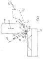
- a bore 18 is formed in the wedge, which extends at an acute angle to the vertical and into which a highly flexible optical waveguide 19 is introduced, to the extent that the free end of the optical waveguide extends as far as the lower contact side of the wedge 10 extends.
- the optical fiber 19 has a diameter of about 100 microns.
- the laser beam which is guided through the optical waveguide 19 is indicated in FIG. 1 by the reference number 20.
- the direction of transport of the bonding wire is shown in FIG. 1 by arrow 21.
- the bond wire has a diameter of approximately 75 ⁇ m.
- the bond pad 14 has a base area of approximately 200 ⁇ 200 ⁇ m 2 .
- FIG. 2 is also only intended to provide an overview of the linking of a conventional bond unit with the laser beam unit according to the invention convey.
- FIG. 3 shows the temperature profiles over time in the two measuring points 26 and 27 identified in FIG. 1. These temperature profiles are shown with T 26 on the one hand and T 27 .
- the measuring point 26 lies at the point of contact of the bonding wire heated by the laser beam with the associated bond pad 14, while the measuring point 27 is located in the wedge 10, in the immediate vicinity of the section of the bonding wire heated by the laser beam.
- the temperature of about 350 ° C. at measuring point 26 required for thermocompression bonding is already reached after about 150 ms.
- a radiation power of about 2 watts in the contact system gives an equilibrium temperature of about 500 ° C.
- the temperature rise in the wedge near the contact point is significantly lower, as the temperature curve T 27 in FIG. 3 shows.
- Fig. 3 shows that the inventive method by short temperature rise times and a low one Power requirement is marked.
- Temperature of the contact point determined during the bonding process of the coupled radiation power and the properties of the contact system itself, like its geometry, Material composition and thermal conductivity. The higher the Radiant power, the shorter the bonding time to get voted.
- Fig. 3 shows that the method described by is characterized sharp temperature profiles, the Heating the bond wire to the contact area thereof is focused.
- Fig. 1 shows very clearly that the described Device can be manufactured extremely easily, in particular by simple modification of a conventional bond unit or one conventional contacting tool (wedge).
- a conventional bond unit or one conventional contacting tool wedge
- the Optical waveguide 19 is preferably by means of a Clamping device attached to the wedge 10 or in the wedge bore 18 glued in. Because of the flexibility of the Optical waveguide 19, the wedge 10 can freely in move in the traditional way.
- the brightest point at time T4 corresponds to one Temperature of about 500 ° C.
Landscapes
- Engineering & Computer Science (AREA)
- Physics & Mathematics (AREA)
- Optics & Photonics (AREA)
- Mechanical Engineering (AREA)
- Plasma & Fusion (AREA)
- Optical Couplings Of Light Guides (AREA)
- Wire Bonding (AREA)
- Lining Or Joining Of Plastics Or The Like (AREA)
Abstract
Description
- große Werkstoffauswahl bei Bonddraht und Metallisierungspad (Al, Au, Ni, Cu, Pd, etc.)
- einfache Prozeßführung und breites Prozeßfenster
- Möglichkeit der Verwendung von lackisolierten Drähten
- hohe mechanische Festigkeit der Bondverbindung
- Verwendung ultraschallempfindlicher Substrate.
- 10 =
- auf- und abbewegbarer Wedge
- 11 =
- Doppelpfeil (zeigt die Auf- und Abbewegung des Wedge 10 an)
- 12 =
- Drahtklemme
- 13 =
- Bonddraht
- 14 =
- Bondpad (Bondstelle)
- 15 =
- Drucksensor
- 16 =
- Drahtzuführung
- 17 =
- Drahtführung an der unteren Kontaktseite des Wedge.
- Anpresskraft (Bondweight)
- Drahtvorschub (Clamp)
- Hubbegrenzung (Limitater Feeder) sowie
- die Messung der Drahtverformung (Touch Down Sensor = TD-Sensor)
- 10
- Kontaktierwerkzeug (Wedge)
- 11
- Doppelpfeil
- 12
- Drahtklemme
- 13
- Bonddraht
- 14
- Bondpad (Bondstelle)
- 15
- Drucksensor
- 16
- Drahtzuführung
- 17
- Drahtführung an der unteren Kontaktseite des Wedge (Drahtführungsnut)
- 18
- Bohrung
- 19
- Lichtwellenleiter
- 20
- Laserstrahl
- 21
- Pfeil
- 22
- Shutter bzw. optischer Schalter
- 23
- Laserstrahlquelle
- 24
- Steuer-PC
- 25
- Monitor
- 26
- Meßpunkt
- 27
- Meßpunkt
Claims (6)
- Vorrichtung zum Thermokompressionsbonden mit einem gegen eine Bondstelle verfahrbaren Kontaktierwerkzeug (Wedge 10) und einem diesem zugeordneten, mit einer Laserstrahlquelle (23) gekoppelten sowie auf einen unterhalb des Wedge (10) zwischen diesem und der Bondstelle (14) angeordneten Bonddraht-Abschnitt gerichteten Lichtwellenleiter (19),
dadurch gekennzeicht, daß
der Lichtwellenleiter (19) durch den Wedge (10) hindurch bis nahe an den sich unterhalb des Wedge (10) befindlichen Bonddraht-Abschnitt (Meßpunkt 26) herangeführt ist, so daß im wesentlichen nur dieser Abschnitt bei Einkoppelung von Laserenergie auf eine zum Thermokompressionsbonden ausreichende Temperatur erwärmbar ist. - Vorrichtung nach Anspruch 1, dadurch gekennzeichnet, daß der Lichtwellenleiter (19) an der der Drahtzuführung (16) gegenüberliegenden Seite des Wedge (10) in diesen eingeführt ist, insbesondere unter einem Winkel von 30° bis 50°, insbesondere etwa 40° bis 45° zur Vertikalen bzw. Anpressrichtung (Doppelpfeil 11) des Wedge (10).
- Vorrichtung nach Anspruch 1 oder 2, dadurch gekennzeichnet, daß der Lichtwellenleiter (19) über einen optischen Schalter (22) mit einer Laserstrahlquelle (23), insbesondere Laserdiode, gekoppelt ist, wobei Laserstrahlquelle und/oder Shutter durch eine Steuereinrichtung (24) in Abhängigkeit vom Bondzyklus ansteuerbar ist bzw. sind.
- Vorrichtung nach einem der Ansrpüche 1 bis 3, dadurch gekennzeichnet, daß die Laserstrahlquelle (23) eine Ausgangsleistung von etwa 2 bis 5 Watt aufweist.
- Thermokompressionsbonden unter Verwendung eines Kontaktierwerkzeuges (Wedge) und einer Laserstrahlquelle, die einen dem Wedge zugeordneten Lichtwellenleiter umfaßt, wobei dieser auf einen sich unter dem Wedge befindlichen Bonddraht-Abschnitt gerichtet ist derart, daß dieser Abschnitt bei Einkoppelung von Laserenergie auf eine zum Thermokompressionsbonden ausreichend hohe Temperatur, insbesondere auf eine Temperatur von etwa 300 °C bis 500 °C, vorzugsweise etwa 350 °C erwärmt wird, bevor der Bonddraht durch den Wedge auf eine Bondstelle gepreßt und mit dieser verschweißt wird.
- Thermokompressionsbonden nach Anspruch 5, dadurch gekennzeichnet, daß die Laserenergie für eine Zeitspanne von etwa 100 ms bis 300 ms, insbesondere etwa 150 ms, eingekoppelt wird.
Applications Claiming Priority (2)
| Application Number | Priority Date | Filing Date | Title |
|---|---|---|---|
| DE19814118A DE19814118A1 (de) | 1998-03-30 | 1998-03-30 | Vorrichtung zum Thermokompressionsbonden, und Thermokompressionsbonden |
| DE19814118 | 1998-03-30 |
Publications (3)
| Publication Number | Publication Date |
|---|---|
| EP0947281A2 true EP0947281A2 (de) | 1999-10-06 |
| EP0947281A3 EP0947281A3 (de) | 2000-02-09 |
| EP0947281B1 EP0947281B1 (de) | 2002-03-27 |
Family
ID=7862927
Family Applications (1)
| Application Number | Title | Priority Date | Filing Date |
|---|---|---|---|
| EP98124759A Expired - Lifetime EP0947281B1 (de) | 1998-03-30 | 1998-12-28 | Vorrichtung und Verfahren zum Thermokompressionsbonden |
Country Status (3)
| Country | Link |
|---|---|
| EP (1) | EP0947281B1 (de) |
| AT (1) | ATE214994T1 (de) |
| DE (2) | DE19814118A1 (de) |
Cited By (4)
| Publication number | Priority date | Publication date | Assignee | Title |
|---|---|---|---|---|
| US7980477B2 (en) | 2007-05-17 | 2011-07-19 | Féinics Amatech Teoranta | Dual interface inlays |
| DE102017127251A1 (de) | 2017-11-20 | 2019-05-23 | Hesse Gmbh | Bondwerkzeug und Herstellverfahren für ein Bondwerkzeug |
| US20220193816A1 (en) * | 2019-09-11 | 2022-06-23 | Hesse Gmbh | Ultrasonic tool and ultrasonic connection device herein |
| US20220193812A1 (en) * | 2019-09-11 | 2022-06-23 | Hesse Gmbh | Device for heating and determining an actual temperature of a bonding tool of an ultrasonic bonding device |
Families Citing this family (3)
| Publication number | Priority date | Publication date | Assignee | Title |
|---|---|---|---|---|
| DE10205609A1 (de) * | 2002-02-11 | 2003-08-28 | Infineon Technologies Ag | Anordnung zum Drahtbonden und Verfahren zur Herstellung einer Bondverbindung |
| ATE472387T1 (de) | 2006-09-05 | 2010-07-15 | Univ Berlin Tech | Verfahren und vorrichtung zur regelung der herstellung von drahtbondverbindungen |
| US8608080B2 (en) | 2006-09-26 | 2013-12-17 | Feinics Amatech Teoranta | Inlays for security documents |
Family Cites Families (7)
| Publication number | Priority date | Publication date | Assignee | Title |
|---|---|---|---|---|
| JPS5889831A (ja) * | 1981-11-24 | 1983-05-28 | Hitachi Ltd | ワイヤボンデイング方法および装置 |
| JPS58173093A (ja) * | 1982-04-05 | 1983-10-11 | Toshiba Corp | ワイヤボンデイング方法 |
| US4534811A (en) * | 1983-12-30 | 1985-08-13 | International Business Machines Corporation | Apparatus for thermo bonding surfaces |
| EP0367705A3 (de) * | 1988-10-31 | 1990-09-26 | International Business Machines Corporation | Laserunterstützte Ultraschallverbindung |
| US4893742A (en) * | 1988-12-21 | 1990-01-16 | Hughes Aircraft Company | Ultrasonic laser soldering |
| DE4337513C2 (de) * | 1993-11-03 | 1998-07-02 | Siemens Ag | Anordnung zum Erwärmen einer Bondstelle beim Goldraht-Thermosonic-Wirebonden |
| DE4437484A1 (de) * | 1994-10-20 | 1996-04-25 | Cms Mikrosysteme Gmbh Chemnitz | Vorrichtung zur Drahtkontaktierung von Bauelementen und Baugruppen |
-
1998
- 1998-03-30 DE DE19814118A patent/DE19814118A1/de not_active Withdrawn
- 1998-12-28 EP EP98124759A patent/EP0947281B1/de not_active Expired - Lifetime
- 1998-12-28 AT AT98124759T patent/ATE214994T1/de not_active IP Right Cessation
- 1998-12-28 DE DE59803509T patent/DE59803509D1/de not_active Expired - Lifetime
Cited By (6)
| Publication number | Priority date | Publication date | Assignee | Title |
|---|---|---|---|---|
| US7980477B2 (en) | 2007-05-17 | 2011-07-19 | Féinics Amatech Teoranta | Dual interface inlays |
| DE102017127251A1 (de) | 2017-11-20 | 2019-05-23 | Hesse Gmbh | Bondwerkzeug und Herstellverfahren für ein Bondwerkzeug |
| US20220193816A1 (en) * | 2019-09-11 | 2022-06-23 | Hesse Gmbh | Ultrasonic tool and ultrasonic connection device herein |
| US20220193812A1 (en) * | 2019-09-11 | 2022-06-23 | Hesse Gmbh | Device for heating and determining an actual temperature of a bonding tool of an ultrasonic bonding device |
| US12097570B2 (en) * | 2019-09-11 | 2024-09-24 | Hesse Gmbh | Ultrasonic tool and ultrasonic connection device herein |
| US12202065B2 (en) * | 2019-09-11 | 2025-01-21 | Hesse Gmbh | Device for heating and determining an actual temperature of a bonding tool of an ultrasonic bonding device |
Also Published As
| Publication number | Publication date |
|---|---|
| EP0947281B1 (de) | 2002-03-27 |
| DE59803509D1 (de) | 2002-05-02 |
| EP0947281A3 (de) | 2000-02-09 |
| DE19814118A1 (de) | 1999-10-14 |
| ATE214994T1 (de) | 2002-04-15 |
Similar Documents
| Publication | Publication Date | Title |
|---|---|---|
| DE68913524T2 (de) | Laserüberschallöten. | |
| EP0204224B1 (de) | Verfahren und Vorrichtung zur Justage und Fixierung eines Festkörpers und damit hergestelltes Bauelement | |
| DE4200492C2 (de) | Vorrichtung zum elektrischen Verbinden von Kontaktelementen | |
| DE3046415C2 (de) | Verfahren zum festen Ankoppeln einer Lichtleiterfaser an ein lichtemittierendes Bauelement | |
| DE60017176T2 (de) | Eine vorrichtung und ein verfahren zum laserschweissen von bändern für elektrische verbindungen | |
| DE68912790T2 (de) | Herstellungsmethode eines Bauelements, das aus einem optoelektronischen Element und einem angekoppelten optischen Wellenleiter besteht. | |
| DE102013011581B4 (de) | Anordnung aus einem Substrat mit mindestens einem optischen Wellenleiter und einer optischen Koppelstelle und aus einem optoelektronischen Bauelement und Verfahren zur Herstellung einer solchen Anordnung | |
| EP0731509A1 (de) | Optoelektronischer Wandler und Herstellverfahren | |
| DE69211850T2 (de) | Verfahren zum löten | |
| EP0947281B1 (de) | Vorrichtung und Verfahren zum Thermokompressionsbonden | |
| DE2529014A1 (de) | Vorrichtung zum verbinden elektrischer leiter mittels waerme und druck, insbesondere schweisskopf | |
| DE60114338T2 (de) | Herstellungsverfahren für optisches Halbleitermodul | |
| EP0111263A2 (de) | Sende- oder Empfangsvorrichtung mit einer mittels eines Trägers gehalterten Diode | |
| EP2768295A2 (de) | Verfahren zum Verschließen eines Gehäuses mittels eines optischen Verbindungsverfahrens | |
| DE3933982C2 (de) | Kontaktierungsverfahren und Kontaktierungsvorrichtung | |
| EP0257076A1 (de) | Verfahren und vorrichtung zum mikrolöten. | |
| DE4494299C1 (de) | Verfahren und Vorrichtung zur Kontaktierung eines Kontaktelements | |
| DE3940933A1 (de) | Verfahren zur verformung von basisplatten | |
| DE19709912A1 (de) | Verfahren und Vorrichtung zum Ultraschallbonden | |
| DE102007062044A1 (de) | Halbleiterlaservorrichtung | |
| DE102019124332A1 (de) | Vorrichtung und Verfahren zum Erfassen einer Temperatur eines Bondwerkzeugs beim laserunterstützen Ultraschallbonden | |
| EP0958089A2 (de) | Vorrichtung zum berührungslosen, selektiven ein- oder auslöten von bauelementen | |
| DE69031963T2 (de) | Bondapparat und Verfahren | |
| DE19749909C2 (de) | Vorrichtung zum Herstellen von Verbindungen zwischen jeweils zwei Kontaktelementen mittels Laserenergie | |
| DE102007007355B4 (de) | Verfahren zur Herstellung optischer Verbindungen und optische Anordnung |
Legal Events
| Date | Code | Title | Description |
|---|---|---|---|
| PUAI | Public reference made under article 153(3) epc to a published international application that has entered the european phase |
Free format text: ORIGINAL CODE: 0009012 |
|
| AK | Designated contracting states |
Kind code of ref document: A2 Designated state(s): AT CH DE FR GB LI |
|
| AX | Request for extension of the european patent |
Free format text: AL;LT;LV;MK;RO;SI |
|
| PUAL | Search report despatched |
Free format text: ORIGINAL CODE: 0009013 |
|
| AK | Designated contracting states |
Kind code of ref document: A3 Designated state(s): AT BE CH CY DE DK ES FI FR GB GR IE IT LI LU MC NL PT SE |
|
| AX | Request for extension of the european patent |
Free format text: AL;LT;LV;MK;RO;SI |
|
| RTI1 | Title (correction) |
Free format text: DEVICE AND METHOD FOR THERMO-COMPRESSION BONDING |
|
| RTI1 | Title (correction) |
Free format text: DEVICE AND METHOD FOR THERMO-COMPRESSION BONDING |
|
| 17P | Request for examination filed |
Effective date: 20000303 |
|
| 17Q | First examination report despatched |
Effective date: 20000828 |
|
| AKX | Designation fees paid |
Free format text: AT CH DE FR GB LI |
|
| GRAG | Despatch of communication of intention to grant |
Free format text: ORIGINAL CODE: EPIDOS AGRA |
|
| GRAG | Despatch of communication of intention to grant |
Free format text: ORIGINAL CODE: EPIDOS AGRA |
|
| GRAH | Despatch of communication of intention to grant a patent |
Free format text: ORIGINAL CODE: EPIDOS IGRA |
|
| REG | Reference to a national code |
Ref country code: GB Ref legal event code: IF02 |
|
| GRAH | Despatch of communication of intention to grant a patent |
Free format text: ORIGINAL CODE: EPIDOS IGRA |
|
| GRAA | (expected) grant |
Free format text: ORIGINAL CODE: 0009210 |
|
| AK | Designated contracting states |
Kind code of ref document: B1 Designated state(s): AT CH DE FR GB LI |
|
| REF | Corresponds to: |
Ref document number: 214994 Country of ref document: AT Date of ref document: 20020415 Kind code of ref document: T |
|
| REG | Reference to a national code |
Ref country code: CH Ref legal event code: EP |
|
| REG | Reference to a national code |
Ref country code: CH Ref legal event code: NV Representative=s name: TROESCH SCHEIDEGGER WERNER AG |
|
| GBT | Gb: translation of ep patent filed (gb section 77(6)(a)/1977) |
Effective date: 20020327 |
|
| REF | Corresponds to: |
Ref document number: 59803509 Country of ref document: DE Date of ref document: 20020502 |
|
| ET | Fr: translation filed | ||
| PLBE | No opposition filed within time limit |
Free format text: ORIGINAL CODE: 0009261 |
|
| STAA | Information on the status of an ep patent application or granted ep patent |
Free format text: STATUS: NO OPPOSITION FILED WITHIN TIME LIMIT |
|
| 26N | No opposition filed |
Effective date: 20021230 |
|
| PGFP | Annual fee paid to national office [announced via postgrant information from national office to epo] |
Ref country code: AT Payment date: 20031223 Year of fee payment: 6 |
|
| PGFP | Annual fee paid to national office [announced via postgrant information from national office to epo] |
Ref country code: CH Payment date: 20031224 Year of fee payment: 6 |
|
| PG25 | Lapsed in a contracting state [announced via postgrant information from national office to epo] |
Ref country code: AT Free format text: LAPSE BECAUSE OF NON-PAYMENT OF DUE FEES Effective date: 20041228 |
|
| PG25 | Lapsed in a contracting state [announced via postgrant information from national office to epo] |
Ref country code: LI Free format text: LAPSE BECAUSE OF NON-PAYMENT OF DUE FEES Effective date: 20041231 Ref country code: CH Free format text: LAPSE BECAUSE OF NON-PAYMENT OF DUE FEES Effective date: 20041231 |
|
| REG | Reference to a national code |
Ref country code: CH Ref legal event code: PL |
|
| PGFP | Annual fee paid to national office [announced via postgrant information from national office to epo] |
Ref country code: GB Payment date: 20071130 Year of fee payment: 10 |
|
| PGFP | Annual fee paid to national office [announced via postgrant information from national office to epo] |
Ref country code: FR Payment date: 20071226 Year of fee payment: 10 |
|
| GBPC | Gb: european patent ceased through non-payment of renewal fee |
Effective date: 20081228 |
|
| REG | Reference to a national code |
Ref country code: FR Ref legal event code: ST Effective date: 20090831 |
|
| PG25 | Lapsed in a contracting state [announced via postgrant information from national office to epo] |
Ref country code: GB Free format text: LAPSE BECAUSE OF NON-PAYMENT OF DUE FEES Effective date: 20081228 |
|
| PG25 | Lapsed in a contracting state [announced via postgrant information from national office to epo] |
Ref country code: FR Free format text: LAPSE BECAUSE OF NON-PAYMENT OF DUE FEES Effective date: 20081231 |
|
| PGFP | Annual fee paid to national office [announced via postgrant information from national office to epo] |
Ref country code: DE Payment date: 20171228 Year of fee payment: 20 |
|
| REG | Reference to a national code |
Ref country code: DE Ref legal event code: R071 Ref document number: 59803509 Country of ref document: DE |