EP0947637A2 - Dämmstoffelement zu Wärme- und/oder Schalldämmzwecken sowie Verfahren und Vorrichtung zur Behandlung, insbesondere Beschichtung von Dämmstoffen - Google Patents
Dämmstoffelement zu Wärme- und/oder Schalldämmzwecken sowie Verfahren und Vorrichtung zur Behandlung, insbesondere Beschichtung von Dämmstoffen Download PDFInfo
- Publication number
- EP0947637A2 EP0947637A2 EP99101171A EP99101171A EP0947637A2 EP 0947637 A2 EP0947637 A2 EP 0947637A2 EP 99101171 A EP99101171 A EP 99101171A EP 99101171 A EP99101171 A EP 99101171A EP 0947637 A2 EP0947637 A2 EP 0947637A2
- Authority
- EP
- European Patent Office
- Prior art keywords
- thermal insulation
- coating
- holes
- needles
- pins
- Prior art date
- Legal status (The legal status is an assumption and is not a legal conclusion. Google has not performed a legal analysis and makes no representation as to the accuracy of the status listed.)
- Granted
Links
- 238000000576 coating method Methods 0.000 title claims abstract description 93
- 239000011248 coating agent Substances 0.000 title claims abstract description 89
- 238000000034 method Methods 0.000 title claims description 22
- 239000011810 insulating material Substances 0.000 title claims description 9
- 239000000835 fiber Substances 0.000 claims abstract description 45
- 239000006260 foam Substances 0.000 claims abstract description 20
- 239000002557 mineral fiber Substances 0.000 claims abstract description 17
- 239000011490 mineral wool Substances 0.000 claims abstract description 9
- 239000011491 glass wool Substances 0.000 claims abstract description 8
- 229920002223 polystyrene Polymers 0.000 claims abstract description 7
- 238000009413 insulation Methods 0.000 claims description 185
- 239000000853 adhesive Substances 0.000 claims description 29
- 230000001070 adhesive effect Effects 0.000 claims description 29
- 239000012774 insulation material Substances 0.000 claims description 14
- 230000035515 penetration Effects 0.000 claims description 10
- 239000002131 composite material Substances 0.000 claims description 9
- 239000011230 binding agent Substances 0.000 claims description 7
- 229920006327 polystyrene foam Polymers 0.000 claims description 7
- 239000004793 Polystyrene Substances 0.000 claims description 6
- 238000004519 manufacturing process Methods 0.000 claims description 6
- 239000007924 injection Substances 0.000 claims description 5
- 238000002347 injection Methods 0.000 claims description 5
- 239000004570 mortar (masonry) Substances 0.000 claims description 5
- 238000004026 adhesive bonding Methods 0.000 claims description 3
- -1 Ormocera Chemical compound 0.000 claims description 2
- 229910019142 PO4 Inorganic materials 0.000 claims description 2
- 230000004323 axial length Effects 0.000 claims description 2
- NBIIXXVUZAFLBC-UHFFFAOYSA-K phosphate Chemical compound [O-]P([O-])([O-])=O NBIIXXVUZAFLBC-UHFFFAOYSA-K 0.000 claims description 2
- 239000010452 phosphate Substances 0.000 claims description 2
- 229920002635 polyurethane Polymers 0.000 claims description 2
- 239000004814 polyurethane Substances 0.000 claims description 2
- 235000019353 potassium silicate Nutrition 0.000 claims description 2
- RMAQACBXLXPBSY-UHFFFAOYSA-N silicic acid Chemical compound O[Si](O)(O)O RMAQACBXLXPBSY-UHFFFAOYSA-N 0.000 claims description 2
- NTHWMYGWWRZVTN-UHFFFAOYSA-N sodium silicate Chemical compound [Na+].[Na+].[O-][Si]([O-])=O NTHWMYGWWRZVTN-UHFFFAOYSA-N 0.000 claims description 2
- 238000011144 upstream manufacturing Methods 0.000 claims description 2
- 238000004873 anchoring Methods 0.000 abstract description 9
- 238000013016 damping Methods 0.000 abstract 1
- 230000000694 effects Effects 0.000 description 8
- 239000000463 material Substances 0.000 description 8
- 239000003292 glue Substances 0.000 description 7
- 239000011505 plaster Substances 0.000 description 6
- 230000001965 increasing effect Effects 0.000 description 5
- 238000010276 construction Methods 0.000 description 4
- 239000002245 particle Substances 0.000 description 4
- 239000004094 surface-active agent Substances 0.000 description 4
- 239000006185 dispersion Substances 0.000 description 3
- 241000446313 Lamella Species 0.000 description 2
- 238000005253 cladding Methods 0.000 description 2
- 239000000155 melt Substances 0.000 description 2
- 239000002184 metal Substances 0.000 description 2
- 239000005011 phenolic resin Substances 0.000 description 2
- 229920001568 phenolic resin Polymers 0.000 description 2
- 239000004033 plastic Substances 0.000 description 2
- 229920003023 plastic Polymers 0.000 description 2
- 239000000243 solution Substances 0.000 description 2
- 239000004575 stone Substances 0.000 description 2
- 210000002268 wool Anatomy 0.000 description 2
- KXGFMDJXCMQABM-UHFFFAOYSA-N 2-methoxy-6-methylphenol Chemical compound [CH]OC1=CC=CC([CH])=C1O KXGFMDJXCMQABM-UHFFFAOYSA-N 0.000 description 1
- 229920003043 Cellulose fiber Polymers 0.000 description 1
- 229920005830 Polyurethane Foam Polymers 0.000 description 1
- 229910000831 Steel Inorganic materials 0.000 description 1
- 239000002969 artificial stone Substances 0.000 description 1
- 239000010426 asphalt Substances 0.000 description 1
- 230000004888 barrier function Effects 0.000 description 1
- 239000000919 ceramic Substances 0.000 description 1
- 239000007795 chemical reaction product Substances 0.000 description 1
- 150000001875 compounds Chemical class 0.000 description 1
- 239000004567 concrete Substances 0.000 description 1
- 230000006378 damage Effects 0.000 description 1
- 238000000280 densification Methods 0.000 description 1
- 230000001419 dependent effect Effects 0.000 description 1
- 230000001066 destructive effect Effects 0.000 description 1
- 238000006073 displacement reaction Methods 0.000 description 1
- 239000004794 expanded polystyrene Substances 0.000 description 1
- 239000004744 fabric Substances 0.000 description 1
- 239000011888 foil Substances 0.000 description 1
- 239000011521 glass Substances 0.000 description 1
- 239000007788 liquid Substances 0.000 description 1
- 230000005923 long-lasting effect Effects 0.000 description 1
- 239000012528 membrane Substances 0.000 description 1
- 239000000203 mixture Substances 0.000 description 1
- 238000005192 partition Methods 0.000 description 1
- 239000002985 plastic film Substances 0.000 description 1
- 229920006255 plastic film Polymers 0.000 description 1
- 229920000582 polyisocyanurate Polymers 0.000 description 1
- 239000011495 polyisocyanurate Substances 0.000 description 1
- 239000011496 polyurethane foam Substances 0.000 description 1
- 230000003014 reinforcing effect Effects 0.000 description 1
- 238000010008 shearing Methods 0.000 description 1
- 230000003584 silencer Effects 0.000 description 1
- 239000010959 steel Substances 0.000 description 1
- 239000000126 substance Substances 0.000 description 1
- 229920001169 thermoplastic Polymers 0.000 description 1
- 229920001187 thermosetting polymer Polymers 0.000 description 1
- 239000004416 thermosoftening plastic Substances 0.000 description 1
- XLYOFNOQVPJJNP-UHFFFAOYSA-N water Chemical compound O XLYOFNOQVPJJNP-UHFFFAOYSA-N 0.000 description 1
- 239000002023 wood Substances 0.000 description 1
Images


Classifications
-
- E—FIXED CONSTRUCTIONS
- E04—BUILDING
- E04B—GENERAL BUILDING CONSTRUCTIONS; WALLS, e.g. PARTITIONS; ROOFS; FLOORS; CEILINGS; INSULATION OR OTHER PROTECTION OF BUILDINGS
- E04B1/00—Constructions in general; Structures which are not restricted either to walls, e.g. partitions, or floors or ceilings or roofs
- E04B1/62—Insulation or other protection; Elements or use of specified material therefor
- E04B1/74—Heat, sound or noise insulation, absorption, or reflection; Other building methods affording favourable thermal or acoustical conditions, e.g. accumulating of heat within walls
- E04B1/76—Heat, sound or noise insulation, absorption, or reflection; Other building methods affording favourable thermal or acoustical conditions, e.g. accumulating of heat within walls specifically with respect to heat only
- E04B1/762—Exterior insulation of exterior walls
-
- E—FIXED CONSTRUCTIONS
- E04—BUILDING
- E04B—GENERAL BUILDING CONSTRUCTIONS; WALLS, e.g. PARTITIONS; ROOFS; FLOORS; CEILINGS; INSULATION OR OTHER PROTECTION OF BUILDINGS
- E04B1/00—Constructions in general; Structures which are not restricted either to walls, e.g. partitions, or floors or ceilings or roofs
- E04B1/62—Insulation or other protection; Elements or use of specified material therefor
- E04B1/74—Heat, sound or noise insulation, absorption, or reflection; Other building methods affording favourable thermal or acoustical conditions, e.g. accumulating of heat within walls
- E04B1/76—Heat, sound or noise insulation, absorption, or reflection; Other building methods affording favourable thermal or acoustical conditions, e.g. accumulating of heat within walls specifically with respect to heat only
- E04B1/78—Heat insulating elements
- E04B1/80—Heat insulating elements slab-shaped
-
- E—FIXED CONSTRUCTIONS
- E04—BUILDING
- E04B—GENERAL BUILDING CONSTRUCTIONS; WALLS, e.g. PARTITIONS; ROOFS; FLOORS; CEILINGS; INSULATION OR OTHER PROTECTION OF BUILDINGS
- E04B1/00—Constructions in general; Structures which are not restricted either to walls, e.g. partitions, or floors or ceilings or roofs
- E04B1/62—Insulation or other protection; Elements or use of specified material therefor
- E04B1/74—Heat, sound or noise insulation, absorption, or reflection; Other building methods affording favourable thermal or acoustical conditions, e.g. accumulating of heat within walls
- E04B1/88—Insulating elements for both heat and sound
- E04B1/90—Insulating elements for both heat and sound slab-shaped
-
- E—FIXED CONSTRUCTIONS
- E04—BUILDING
- E04B—GENERAL BUILDING CONSTRUCTIONS; WALLS, e.g. PARTITIONS; ROOFS; FLOORS; CEILINGS; INSULATION OR OTHER PROTECTION OF BUILDINGS
- E04B1/00—Constructions in general; Structures which are not restricted either to walls, e.g. partitions, or floors or ceilings or roofs
- E04B1/62—Insulation or other protection; Elements or use of specified material therefor
- E04B1/74—Heat, sound or noise insulation, absorption, or reflection; Other building methods affording favourable thermal or acoustical conditions, e.g. accumulating of heat within walls
- E04B1/82—Heat, sound or noise insulation, absorption, or reflection; Other building methods affording favourable thermal or acoustical conditions, e.g. accumulating of heat within walls specifically with respect to sound only
- E04B1/84—Sound-absorbing elements
- E04B2001/8457—Solid slabs or blocks
- E04B2001/8461—Solid slabs or blocks layered
- E04B2001/8471—Solid slabs or blocks layered with non-planar interior transition surfaces between layers, e.g. faceted, corrugated
Definitions
- the invention relates to an insulation element for heat and / or sound insulation purposes, especially in connection with thermal insulation composite systems, consisting of a thermal insulation board, in particular of mineral fibers, preferably made of glass or rock wool fibers or polystyrene rigid foam, with an applied at least on a large surface Coating for at least partial gluing of the thermal insulation board with cover layers or load-bearing surfaces.
- a thermal insulation board in particular of mineral fibers, preferably made of glass or rock wool fibers or polystyrene rigid foam
- Invention a method for the treatment, in particular coating of Insulating materials with a coating for at least partial bonding a thermal insulation board made of the insulating material with cover layers or load-bearing surfaces, the thermal insulation board in particular Mineral fibers, preferably made of glass or rock wool fibers, or rigid polystyrene foam exists and the coating on at least one large one Surface of the thermal insulation board is applied.
- the concerns Invention a device for the treatment, in particular coating of Insulating materials according to the above-mentioned procedure.
- insulation elements for heat and / or Sound insulation is a frictional connection to the load-bearing surfaces on the one hand and / or cover layers on the other hand.
- Flat roof constructions are known in which the insulation elements are glued to load-bearing concrete or profiled sheet metal surfaces and onto the even a water-draining layer of bitumen sheets or plastic films is glued on.
- pitched roof insulation water vapor permeable, but water-draining foils through partial gluing connected to the thermal insulation material.
- the wind suction works in both cases permanently or only during the construction phase of the sloping roof Composite of the insulation element and the cover.
- thermal insulation composite systems the thermal insulation panels are placed on one Underground, for example an external facade glued on and if necessary plaster layers on the exposed surfaces of the insulation elements or ceramic plates applied non-positively. In these cases, the Dead load in connection with the wind suction on the composite thermal insulation system on.
- shear-resistant insulation elements for example Made of non-combustible mineral wool, with smooth or profiled surfaces on both sides to glue. These elements are called partitions and / or external walls and / or ceilings and as bulkheads on ships etc.
- Mineral wool insulation materials rigid polystyrene foams, Rigid polyurethane foams, rigid polyisocyanurate foams and Phenolic resin rigid foams most often used as insulation materials.
- insulation elements made from cellulose fibers and / or other organic fibers. With these insulation elements exist with regard to their insulation properties and their applicability Advantages and disadvantages that are known per se and not here to be discussed further.
- Insulation elements made of mineral fibers consist of glassy solidified fibers with different chemical compositions. These fibers are with relatively brittle binders such as thermosetting phenolic resins, ormocers or the like.
- glass wool and Stone wool insulation materials distinguished, the stone wool insulation materials in usually a higher bulk density compared to glass wool insulation exhibit.
- Glass wool insulation materials and rock wool insulation materials are listed under the term mineral wool insulation materials summarized, the fibers have average diameters of about three to six microns, different long and smooth or curved in the insulation element are. The fibers are usually parallel or at a very flat angle to the two large surfaces of the insulation element. But there are also known as so-called lamella plates, in which the individual fibers are steep right up to the large, mostly adhesive surfaces are arranged.
- the tensile and compressive strength of these slat plates is compared to the insulation elements with parallel to the large ones Surface running fibers increased significantly.
- the anisotropy of strength properties is used, for example, with so-called slat mats exploited.
- relatively narrow slats are glued to a carrier film.
- the lamellas are perpendicular to the large surfaces Pressure resistant and compressible in the horizontal direction so that the mats can be rolled up relatively easily and at the same time during application these slat mats on a surface have a sufficiently high compressive strength exhibit.
- the fibers stored horizontally or flat against the large surfaces, to which an adhesive is to be applied form excellent fine filters, so that only real solutions, nanometer sized particles or up to a few micrometers in diameter can.
- To allow the glue to penetrate the large surfaces more to enable it is known to the adhesive or a corresponding coating to be incorporated under pressure into the surfaces of the insulation element. It has been shown, however, that the filter effect is due to this pressure by increasing the spacing between the fibers.
- solvent-free adhesives cannot do without this pressure, to overcome the hydrophobicity of the fibers.
- the hydrophobicity could also be overcome by adding surfactants. It would then be possible to do without the print.
- Another special feature of the insulation elements consists of mineral fibers in that not all fibers are evenly fixed with binders. It there are therefore not inconsiderable proportions of unbound fibers within of the insulation element. Through these unbound fibers the Transverse tensile strength of the insulation element significantly reduced, especially since unbound fibers often close to the large ones due to production Surfaces are stored. In addition, they also have an increasing effect Dimensions in the production of insulation elements from mineral fibers introduced recycled fibers reduce strength. These recycled fibers are made in the usual manufacturing process from insulation elements Mineral fibers are blown into a collection chamber, but cannot be integrated into the fiber mass to the same extent as the fibers in statu nascendi.
- such insulation elements are made from mineral fibers manufactured in the way that natural or artificial stones in melted in a cupola furnace and the melt then one Fiberizer is fed.
- the Melt defibrated into microfine fibers, which at least subsequently Binding agents are wetted and placed on a continuous conveyor.
- This Continuous conveyor then forms an endless mineral fiber layer, each processed according to the desired end product, i.e. for example compacted as well as horizontally and vertically.
- Other processing or Processing stages are also known.
- insulation elements made of rigid polystyrene foam for the foregoing applications are provided.
- the surfaces of as Ribbon or block foam expanded polystyrene rigid foam have from Naturally good adhesion, among other things to commercial building adhesives or plastic-doped plasters.
- the specific surface area increases due to the concave domed membranes of the individual foam balls.
- the gussets remain stand raised between the foamed balls, so that the Connect adhesive or plastic-doped plaster to the webs from both sides or anchored to the micro scales.
- the insulation elements described above are usually on site with the appropriate coatings, for example Spread adhesive mortars and / or plastic dispersions before the insulation elements be glued on the building side or the final plaster is applied. But it is also known, the coatings of the insulation elements already provided in the factory, so that the insulation elements provided with a hardened coating on site can be. Both the application of a factory coating as also applying a coating on site, i.e. on site can the above-described disadvantages with regard to processability of the insulation elements.
- the invention has for its object to provide an insulating element of the generic type with a coating in which the connection between the coating and the insulating element is improved. Furthermore, it is an object of the invention to provide a device and a method for coating an insulating element of the generic type, with which or with which an improved insulating element can be produced in a simple and economical manner.
- the solution to this problem provides for a generic insulation element that the thermal insulation board is perforated at least in the area of the large surface or surfaces having the coating and has a plurality of holes open to the coating and that the coating forms protrusions that enter the holes intervene so that the hardened coating has a nail-shaped structure anchored in the thermal insulation panel.
- the insulation element thus consists of a thermal insulation panel, for example made of mineral fibers or polystyrene rigid foam, and a coating that is at least on a surface of the thermal insulation panel is arranged.
- the thermal insulation board has a large number of right angles to the large surface to be coated should, extending openings, in particular holes in which the to be applied Coating can penetrate to deep anchoring in the thermal insulation board to achieve. This will result in a much better liability, especially solvent-free dispersion glue or based on hydraulically hardening binders built up adhesive or combinations achieved from it.
- thermal insulation boards made of rigid polystyrene foam It has been shown that the more intensive interlocking of the thermal insulation board with the Coating a possible tear of the adhesive or plaster layer on the Counteracts surface of the insulation board, so that such a trained Insulation element has a significantly increased transverse tensile strength.
- the thermal insulation board is preferably needled. It has proven to be advantageous that the thermal insulation board has 5 to 20 holes per cm 2 , in particular 8 to 10 holes per cm 2 in the case of fibrous thermal insulation boards or 10 to 16 holes per cm 2 in the case of rigid foam thermal insulation boards. This number of holes is sufficient to achieve an intimate connection between the thermal insulation board and the coating over the entire surface of the insulating material element, the thermal insulation board not being significantly weakened.
- the holes have a diameter of 1 to 5 mm, preferably 2 to 3 mm, depending on their dense arrangement in the large surface of the thermal insulation board, at least in the area of the large surface.
- the nail-shaped projections of the coating must be dimensioned to be sufficiently stable to prevent the coating from shearing off its nail-shaped projections.
- good results can also be achieved with coarser punctures and a correspondingly smaller number of punctures or impressions per cm 2 .
- the structure of the insulation element is essential when dimensioning the number of punctures and the material thickness of the nail-shaped protrusions of the coating that engage in the punctures. This includes fiber orientation, bulk density, binder content and the elasticity of the fibers.
- the holes are preferably conical and / or frustoconical formed so that each hole ends in a tip.
- the holes are preferred cylindrical, truncated and / or frustoconical and / or truncated pyramid each with dome-shaped or spherical segment-shaped Ends formed.
- the holes are dependent on the bulk density of the insulating materials to be treated, so that a safe Placing the coating in the holes is possible.
- the insulation element to form a thermal insulation board coated on both sides.
- the holes in both large surfaces of the Thermal insulation board have it proved advantageous to drill the holes in both large surfaces of the Thermal insulation board to be arranged offset to each other, so that a connection the holes on both surfaces do not exist.
- Such a connection would by applying the coating compound if necessary lead to thermal bridges that prevent such insulation elements are.
- there is the staggered arrangement of the holes the possibility of deep anchoring in both large surfaces to achieve with such insulation elements that only a small material thickness have so that each anchoring of the coating larger than that Half of the material thickness of the insulation element can be formed.
- the thermal insulation board is perforated, in particular needled, before and / or when the coating is applied, at least in the region of the surface to be coated.
- Both large surfaces of the thermal insulation boards are preferred perforated, in particular needled and then coated, the Holes in the opposite surfaces are staggered become.
- the coating can be done both manually and mechanically the surface of the thermal insulation board can be incorporated.
- a further improvement of the process in terms of an intimate connection between the thermal insulation board and the coating achieved that a relatively thin adhesive as a coating in the perforation injected and a relatively granular adhesive mortar or the like on the Surface is arranged.
- thermal insulation materials polyurethane injections have been used as the coating proven, whereas injections with filled silica sol, ormocera, Water glass, phosphate binders or the like with thermally resilient Thermal insulation materials are an advantage. It is procedural finally advantageous, after the first factory coating apply second coating.
- a device for performing the method described above intended for treatment, in particular coating of insulation materials which consists of at least one carrier with a multitude in the direction aligned with an insulation layer, in particular rotationally symmetrical trained needles or pins, the carrier of a coating device upstream, which is part of a continuous working insulation production plant.
- the pins or needles are conical to their free end, wherein at least the free end has the taper and the pins or needles are otherwise cylindrical. This configuration enables one as possible non-destructive penetration of the pins or needles in the thermal insulation board.
- the carrier is preferably opened and closed at right angles to the insulation surface arranged movable down.
- the carrier to be designed as a rotating roller, the needles or pins being radial are arranged progressively. It is preferred that the needles or pins are frustoconical or truncated pyramid.
- Another feature of this embodiment is the possibility of the basis the truncated pyramid-shaped needles or pins in the direction of rotation the roller narrower than in the axial direction of the roller.
- the needles or pins have barbs at their free ends, which in particular are then advantageous if thermal insulation boards made of rigid polystyrene foam should be processed procedurally as these barbs an increase in the specific surface area by tearing open or pulling out allow material from the surface.
- 8 to 10 punctures per cm 2 are pressed into the surface of the thermal insulation panel in the case of fibrous insulation elements.
- the diameters of the punctures are, for example, approximately 1 to approximately 5 mm, but preferably 2 to 3 mm.
- Pins or needles made of high-strength steels, for example, are suitable for producing such holes in a thermal insulation board.
- the shape of the pins depends on the type of thermal insulation board. In the case of thermal insulation boards, the fibers of which run parallel to the large surfaces, it has proven to be advantageous to preferably let the pins run out into a tip. In thermal insulation boards with fibers arranged essentially at right angles to the surfaces, rounded pins are particularly suitable, since the effect of lateral displacement of the fibers predominates here.
- the raw density of the thermal insulation board plays a significant role in the selection of the appropriate pins.
- the pins are mostly for processing thermal insulation boards Slabs of metal, wood, wooden materials put on at right angles be moved up and down to the insulation surfaces. At this The procedure is the effect of cavitation in the surface of the Thermal insulation board largely independent of the orientation of the fibers in the surface zone.
- Surface-running fibers can also be used in pens frustoconical or truncated pyramid-shaped and on a roller are attached.
- the base of the truncated pyramid-shaped pins can be in Direction of rotation of the roller be significantly narrower than coaxial to the roller. At In this configuration, the tips of the pins are rounded to one to effect gentle intervention.
- the openings in the thermal insulation board can with respect to their diameter or opening widths and their depth depending on the characteristic the thermal insulation panel.
- the viscosity play and the particle size of the adhesives also play an important role.
- the anchoring technique is limited i.a. in that the thermal resistance of the insulation should not be changed or should only be changed insignificantly.
- the essential Advantage of the inventive method and the inventive Device is that the treated insulation elements despite the Imperfections common on construction sites and without additional applications Treatment methods, for example in composite thermal insulation systems, are significantly improved in their average transverse tensile strengths. At The manufacture of coatings at the factory can of course affect the quality and Uniformity of the coating can be significantly improved.
- its depth and the viscosity of the glue is the one on the glue applied pressure down to the depth of the cavity. Under this Pressure the adhesive is also pressed into the side areas of the cavities.
- the adhesive can also get between the fibers horizontally, so that the anchoring of the coating with the thermal insulation board clearly improved.
- the fibers are locally compressed, that are between the cavities.
- the additional side gearing and together increase the local densification around the cavities with the specific bonding area increased by the cavities the strength of the insulation element is very important.
- the strength properties of the insulation element can be determined increase by varying the injection depth. In extreme cases the penetration can reach the entire thickness of the thermal insulation board. In order to minimize the resulting thermal bridges, that the thermal insulation board on its two large surfaces accordingly the method according to the invention is processed, the perforation is staggered.
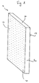
- a thermal insulation board 1 shown in FIG. 1 has a large upper one Surface 2, a lower large surface 3, narrow sides 4 and long sides 5 on.
- the thermal insulation board 1 is cuboid, so that the surfaces 2, 3 each perpendicular to the narrow sides 4 and Longitudinal sides 5 are arranged.
- the large surface 2 is in a uniform pattern with the surface 1 open holes 6.
- the thermal insulation panel designed in this way 1 is for receiving a coating, for example an adhesive mortar or a plastic dispersion, the one in Figure 1 not coating shown in detail is applied to the surface 2 and penetrates into the holes 6 for intimate anchoring to the thermal insulation panel 1 to enter.
- FIGS. 2 to 4 show different configurations of insulation elements shown, each of a thermal insulation board 1 and a coating 8 exist.
- the holes 6 are predominantly cylindrical and are conical in their closed end.
- the coating 8 can also be parallel to the large surfaces 2, 3 aligned anchoring with the fibers 9 of the thermal insulation board 1 received. It can also be seen in FIG. 2 that the coating 8 is arranged in a region of the thermal insulation panel 1 near the surface.
- FIG. 3 shows a section of an insulation element 7, in which the coating 8, the thermal insulation board 1 on their penetrates the entire material thickness.
- the holes 6 are in this embodiment cylindrical.
- FIG. 4 shows an insulation element 7, which is on both Surfaces 2 and 3 is provided with a coating 8.
- This one too Embodiment has the thermal insulation element 1 at right angles to its Surfaces 2 and 3 arranged holes 6, which are pyramidal formed and after applying the coatings 8 with coating material are filled out.
- thermal bridges in the insulating element 7 To avoid, the holes of the two surfaces 2, 3 are offset from one another arranged so that a connection between the in the thermal insulation board 1 reaching wedge made of adhesive does not exist.
- FIG. 5 shows a device 10 for treatment, in particular Coating of insulation elements.
- This device 10 is made from a carrier 11, which is linear motors 12 in the vertical direction an insulation layer, not shown, to or from this insulation layer is movable away.
- the carrier 11 has a plurality of needles 12, which are essentially are cylindrical and have a conical tip. These needles 12 penetrate the thermal insulation board 1 and perforate the thermal insulation board 1 for example with a pattern as shown in Figure 1 is.
- a part of the needles is designed as a hollow needle 13, each hollow needle 13 a centrally arranged channel 14 running in the axial direction which channel 14 is connected to a supply line 15.
- Adhesive material 14 is fed to the hollow needle 13 via the feed line 15, which with the support 11 lowered and into the thermal insulation board 1 penetrated needles 12 or 13 is injected into the thermal insulation board 1.
- all needles 12 correspond to the hollow needles 13 are formed.
- a thermal insulation board 1 perforated before a coating 8 on the perforated large surface the thermal insulation panel is applied to an insulation element 7 to build.
- the liquid coating 8 penetrates at least into the holes 6 of the perforation and preferably also in the vicinity of these holes 6 between the fibers 9, so that the coating 8 not only on the Surface of the thermal insulation board 1 adheres, but also indoors the thermal insulation board 1 is anchored.
- the coating 8 After the coating 8 has hardened, there is the possibility of a further one Apply coating so that insulation elements 7 are produced that are highly resilient and, for example, in composite thermal insulation systems can be provided with clinker cladding.
- the second Coating can also be done at the factory or on site, i.e. on the site be applied. Make sure that the second coating an intimate connection with the first coating.
Landscapes
- Physics & Mathematics (AREA)
- Engineering & Computer Science (AREA)
- Architecture (AREA)
- Acoustics & Sound (AREA)
- Electromagnetism (AREA)
- Civil Engineering (AREA)
- Structural Engineering (AREA)
- Building Environments (AREA)
- Laminated Bodies (AREA)
- Lining Or Joining Of Plastics Or The Like (AREA)
- Adhesives Or Adhesive Processes (AREA)
- Paints Or Removers (AREA)
- Application Of Or Painting With Fluid Materials (AREA)
- Encapsulation Of And Coatings For Semiconductor Or Solid State Devices (AREA)
- Design And Manufacture Of Integrated Circuits (AREA)
- Element Separation (AREA)
Abstract
Description
- Figur 1
- eine Wärmedämmplatte für ein Dämmstoffelement in perspektivischer Ansicht;
- Figur 2
- ein Abschnitt eines Dämmstoffelementes im Querschnitt;
- Figur 3
- eine zweite Ausführungsform eines Dämmstoffelementes im Querschnitt;
- Figur 4
- eine dritte Ausführungsform eines Dämmstoffelementes im Querschnitt und
- Figur 5
- einen Abschnitt einer Vorrichtung zur Beschichtung von Dämmstoffen in Seitenansicht.
Claims (30)
- Dämmstoffelement zu Wärme- und/oder Schalldämmzwecken, insbesondere in Verbindung mit Wärmedämmverbundsystemen, bestehend aus einer Wärmedämmplatte, insbesondere aus Mineralfasern, vorzugsweise aus Glas- oder Steinwollefasern, oder Polystyrol-Hartschaum, mit einer zumindest auf einer großen Oberfläche aufgebrachten Beschichtung zur zumindest partiellen Verklebung der Wärmedämmplatten mit Deckschichten bzw. tragenden Flächen,
dadurch gekennzeichnet,
daß die Wärmedämmplatte (1) zumindest im Bereich der die Beschichtung (8) aufweisenden großen Obefläche (2) bzw. Oberflächen (2, 3) perforiert ausgebildet ist und eine Vielzahl von zur Beschichtung (8) hin offenen Löchern (6) aufweist und
daß die Beschichtung (8) Vorsprünge ausbildet, die in die Löcher (6) eingreifen, so daß die ausgehärtete Beschichtung (8) eine nagelförmige, in der Wärmedämmplatte (1) verankerte Struktur hat. - Dämmstoffelement nach Anspruch 1,
dadurch gekennzeichnet,
daß die Wärmedämmplatte (1) genadelt ist. - Dämmstoffelement nach Anspruch 1,
dadurch gekennzeichnet,
daß die Wärmedämmplatte (1) 5 bis 20 Löcher (6) pro cm2, insbesondere 8 bis 10 Löcher (6) pro cm2 bei faserigen Wärmedämmplatten (1) bzw. 10 bis 16 Löcher (6) bei Hartschaum-Wärmedämmplatten (1) aufweist. - Dämmstoffelement nach Anspruch 1,
dadurch gekennzeichnet,
daß die Löcher (6) in Abhängigkeit ihrer dichten Anordnung in der großen Oberfläche (2) der Wärmedämmplatte (1) zumindest im Bereich der großen Oberfläche (2) Durchmesser von 1 bis 5 mm, vorzugsweise 2 bis 3 mm aufweist. - Dämmstoffelement nach Anspruch 1,
dadurch gekennzeichnet,
daß die Mineralfasern im wesentlichen parallel zu den großen Oberflächen (2, 3) verlaufen und die Löcher (6) kegel- und/oder kegelstumpfförmig ausgebildet sind. - Dämmstoffelement nach Anspruch 1,
dadurch gekennzeichnet,
daß die Mineralfasern im wesentlichen rechtwinklig oder geneigt zu den großen Oberflächen (2, 4) verlaufen und die Löcher (6) zylindrisch, kegelund/oder kegelstumpfförmig und/oder pyramidenstumpfförmig mit jeweils kalottenförmigen oder kugelabschnittförmigen Enden ausgebildet sind. - Dämmstoffelement nach Anspruch 1,
dadurch gekennzeichnet,
daß die Löcher (6) im wesentlichen rechtwinklig zu den großen Oberflächen (2, 3) der Wärmedämmplatte (1) ausgerichtet sind. - Dämmstoffelement nach Anspruch 1,
dadurch gekennzeichnet,
daß die Löcher (6) in beiden großen Oberflächen (2, 3) der Wärmedämmplatte (1) versetzt zueinander angeordnet sind. - Dämmstoffelement nach Anspruch 1,
dadurch gekennzeichnet,
daß die Löcher (6) bei Hartschaum-Wärmedämmplatten eine axiale Länge kleiner gleich 5 mm aufweisen. - Verfahren zur Behandlung, insbesondere Beschichtung von Dämmstoffen mit einer Beschichtung zur zumindest partiellen Verkleben einer aus dem Dämmstoff hergestellen Wärmedämmplatte mit Deckschichten bzw. tragenden Flächen, wobei die Wärmedämmplatte insbesondere aus Mineralfasern, vorzugsweise aus Glas- oder Steinwollfasern oder Polystyrol-Hartschaum besteht und die Beschichtung auf zumindest einer großen Oberfläche der Wärmedämmplatte aufgebracht wird,
dadurch kennzeichnet,
daß die Wärmedämmplatte (1) vor dem und/oder beim Aufbringen der Beschichtung (8) zumindest im Bereich der zu beschichtenden Oberfläche (2) perforiert, insbesondere genadelt wird. - Verfahren nach Anspruch 10,
dadurch gekennzeichnet,
daß in die zu beschichtende große Oberfläche (2) 5 bis 20 Löcher pro cm2, insbesondere 8 bis 10 Löcher pro cm2 bei faserigen Wärmedämmplatten (1) bzw. 10 bis 16 Löcher pro cm2 bei Hartschaum-Wärmedämmplatten (1) eingebracht werden. - Verfahren nach Anspruch 10,
dadurch gekennzeichnet,
daß beide großen Oberflächen (2, 3) der Wärmedämmplatte (1) perforiert, insbesondere genadelt und anschließend beschichtet werden, wobei die Löcher (6) in den gegenüberliegenden Oberflächen (2, 3) versetzt zueinander angeordnet werden. - Verfahren nach Anspruch 10,
dadurch gekennzeichnet,
daß die Beschichtung (8) werkseitig aufgebracht wird. - Verfahren nach Anspruch 10,
dadurch gekennzeichnet,
daß die Beschichtung (8) manuell und/oder maschinell in die Oberfläche (2) der Wärmedämmplatte (1) eingearbeitet wird. - Verfahren nach Anspruch 10,
dadurch gekennzeichnet,
daß die Beschichtung (8) unter Druck auf die Oberfläche (2) der Wärmedämmplatte (1) appliziert und in die Perforation eingepreßt wird. - Verfahren nach Anspruch 10,
dadurch gekennzeichnet,
daß als Beschichtung (8) ein relativ dünnflüssiger Kleber gezielt in die Perforation injiziert und relativ dazu körniger Klebemörtel oder dergleichen auf der Oberfläche (2) angeordnet werden. - Verfahren nach Anspruch 10,
dadurch gekennzeichnet,
daß als Beschichtung (8) Polyurethan-Injektionen bei Wärmedämmstoffen oder Injektionen mit gefülltem Kieselsol, Ormoceren, Wasserglas, Phosphatbindern oder dergleichen bei thermisch belastbaren Wärmedämmstoffen verwendet werden. - Verfahren nach Anspruch 10,
dadurch gekennzeichnet,
daß nach der ersten werkseitigen Beschichtung eine zweite Beschichtung aufgebracht wird. - Vorrichtung zur Behandlung, insbesondere Beschichtung von Dämmstoffen nach dem Verfahren gemäß den Ansprüchen 10 bis 18, bestehend aus zumindest einem Träger (11) mit einer Vielzahl in Richtung auf eine Dämmstofflage ausgerichteten, insbesondere rotationssymmetrisch ausgebildeten Nadeln oder Stiften, wobei der Träger (11) einer Beschichtungseinrichtung vorgeschaltet ist, die Bestandteil einer kontinuierlich arbeitenden Dämmstoffproduktionsanlage ist.
- Vorrichtung nach Anspruch 19,
dadurch gekennzeichnet,
daß die Stifte oder Nadeln (12) zu ihrem freien Ende hin konisch ausgebildet sind, wobei zumindest das freie Ende die Konizität aufweist und die Stifte oder Nadeln (12) im übrigen zylindrisch ausgebildet sind. - Vorrichtung nach Anspruch 19,
dadurch gekennzeichnet,
daß der Träger (11) im rechten Winkel zur Dämmstofffläche auf- und niederbewegbar angeordnet ist. - Vorrichtung nach Anspruch 19,
dadurch gekennzeichnet,
daß der Träger (11) als rotierende Walze ausgebildet ist, wobei die Nadeln (12) oder Stifte radial verlaufend angeordnet sind. - Vorrichtung nach Anspruch 22,
dadurch gekennzeichnet,
daß die Nadeln (12) oder Stifte kegelstumpf- oder pyramidenstumpfförmig ausgebildet sind. - Vorrichtung nach Anspruch 23,
dadurch gekennzeichnet,
daß die Basis der pyramidenstumpfförmig ausgebildeten Nadeln (12) oder Stifte in Drehrichtung der Walze schmaler als in Achsrichtung der Walze ausgebildet ist. - Vorrichtung nach Anspruch 22,
dadurch gekennzeichnet,
daß die freien Enden der Nadeln (12) oder Stifte abgerundet ausgebildet sind. - Vorrichtung nach Anspruch 19,
dadurch gekennzeichnet,
daß der Träger (11) höhenverstellbar gelagert ist. - Vorrichtung nach Anspruch 19,
dadurch gekennzeichnet,
daß zumindest ein Teil der Stifte oder Nadeln (12) hohl ausgebildet ist und einen Kanal (14) zur Durchleitung eines dünnflüssigen Klebers aufweist. - Vorrichtung nach Anspruch 19,
dadurch gekennzeichnet,
daß der Träger (11) pro cm2 5 bis 20 Nadeln (12) oder Stifte, insbesondere 8 bis 10 Nadeln (12) oder Stifte bei der Penetration faseriger Wärmedämmplatten (1) bzw. 10 bis 16 Nadeln (12) oder Stifte bei der Penetration von Hartschaum-Wärmedämmplatten (1) aufweisen. - Vorrichtung nach Anspruch 19,
dadurch gekennzeichnet,
daß die Nadeln (12) oder Stifte einen Durchmesser größer gleich 2 mm aufweisen. - Vorrichtung nach Anspruch 19,
dadurch gekennzeichnet,
daß die Nadeln (12) oder Stiften an ihren freien Enden Widerhaken aufweisen.
Priority Applications (1)
| Application Number | Priority Date | Filing Date | Title |
|---|---|---|---|
| EP05010945A EP1564338B1 (de) | 1998-04-04 | 1999-01-22 | Vorrichtung zur Herstellung von Dämmstoffelementen |
Applications Claiming Priority (2)
| Application Number | Priority Date | Filing Date | Title |
|---|---|---|---|
| DE19815170 | 1998-04-04 | ||
| DE19815170A DE19815170C5 (de) | 1998-04-04 | 1998-04-04 | Dämmstoffelement zu Wärme- und/oder Schalldämmzwecken sowie Verfahren und Vorrichtung zur Behandlung, insbesondere Beschichtung von Dämmstoffen |
Related Child Applications (1)
| Application Number | Title | Priority Date | Filing Date |
|---|---|---|---|
| EP05010945A Division EP1564338B1 (de) | 1998-04-04 | 1999-01-22 | Vorrichtung zur Herstellung von Dämmstoffelementen |
Publications (3)
| Publication Number | Publication Date |
|---|---|
| EP0947637A2 true EP0947637A2 (de) | 1999-10-06 |
| EP0947637A3 EP0947637A3 (de) | 2000-06-14 |
| EP0947637B1 EP0947637B1 (de) | 2006-03-29 |
Family
ID=7863615
Family Applications (2)
| Application Number | Title | Priority Date | Filing Date |
|---|---|---|---|
| EP99101171A Expired - Lifetime EP0947637B1 (de) | 1998-04-04 | 1999-01-22 | Dämmstoffelement zu Wärme- und/oder Schalldämmzwecken sowie Verfahren zur Behandlung, insbesondere Beschichtung von Dämmstoffen |
| EP05010945A Expired - Lifetime EP1564338B1 (de) | 1998-04-04 | 1999-01-22 | Vorrichtung zur Herstellung von Dämmstoffelementen |
Family Applications After (1)
| Application Number | Title | Priority Date | Filing Date |
|---|---|---|---|
| EP05010945A Expired - Lifetime EP1564338B1 (de) | 1998-04-04 | 1999-01-22 | Vorrichtung zur Herstellung von Dämmstoffelementen |
Country Status (3)
| Country | Link |
|---|---|
| EP (2) | EP0947637B1 (de) |
| AT (2) | ATE321921T1 (de) |
| DE (3) | DE19815170C5 (de) |
Cited By (9)
| Publication number | Priority date | Publication date | Assignee | Title |
|---|---|---|---|---|
| WO2000073600A1 (en) * | 1999-05-27 | 2000-12-07 | Rockwool International A/S | Mineral fibre insulating board comprising a rigid surface layer, a process for the preparation thereof and a use of the insulating product for roofing and facade covering |
| EP1270837A3 (de) * | 2001-06-28 | 2003-12-03 | Austyrol Dämmstoffe Ges.m.b.H. | Wärmedämmung von Wänden und/oder Decken von Gebäuden |
| AT414226B (de) * | 2004-07-07 | 2006-10-15 | Siemens Transportation Systems | Schalen-/plattenförmiges bauelement |
| ES2354316A1 (es) * | 2008-06-16 | 2011-03-14 | Eduardo Martinez Muñoz | Procedimiento de preparación de una placa de escayola o equivalente con propiedades aislantes, ignífugas e impermeables sustancialmente mejoradas. |
| CN105220778A (zh) * | 2015-10-27 | 2016-01-06 | 张荣斌 | 一种建筑外墙隔热结构 |
| CN105401664A (zh) * | 2016-01-18 | 2016-03-16 | 张荣斌 | 一种建筑外墙隔热结构的施工工艺 |
| CN107304583A (zh) * | 2016-04-21 | 2017-10-31 | 山西铭坤建材有限公司 | 一种a级新型防火保温材料 |
| CN107304580A (zh) * | 2016-04-21 | 2017-10-31 | 山西铭坤建材有限公司 | 一种a级防火保模一体化板 |
| CN117188081A (zh) * | 2023-09-26 | 2023-12-08 | 波司登羽绒服装有限公司 | 一种热定型板、单向导湿面料和服装 |
Families Citing this family (11)
| Publication number | Priority date | Publication date | Assignee | Title |
|---|---|---|---|---|
| DE19959336C2 (de) | 1999-12-09 | 2003-05-15 | Rockwool Mineralwolle | Dämmstoffelement |
| DE10007774A1 (de) * | 2000-02-14 | 2001-09-20 | Wki Isoliertechnik Gmbh Berlin | Wärmedämmplatte aus Polystyrol (EPS/XPS) oder Polyurethan (PUR) mit niedriger Wasserdampfdiffusionszahl mu 10 |
| DE10024678A1 (de) * | 2000-02-14 | 2001-11-29 | Wki Isoliertechnik Gmbh Berlin | Wärmedämmplatte aus Polystyrol (EPS/XPS) oder Polyurethan (PUR) mit niedriger Wasserdampfdiffusionszahl kleiner 10mu mit äußerer Beschichtung |
| DE10248326C5 (de) * | 2002-07-19 | 2014-06-12 | Deutsche Rockwool Mineralwoll Gmbh & Co. Ohg | Dämmschicht aus Mineralfasern |
| DE102009010777B4 (de) * | 2009-02-26 | 2012-10-04 | Renke Fuhrmann | Verfahren und Vorrichtung zum Beschichten von offenporigen Substraten |
| RU2012150891A (ru) | 2010-04-28 | 2014-06-10 | ДАУ ГЛОБАЛ ТЕКНОЛОДЖИЗ ЭлЭлСи | Многослойные пеноматериалы с сопряженными выступами и канавками |
| DE202010013540U1 (de) * | 2010-05-20 | 2010-12-09 | Wedi, Stephan | Dreischichtige Bauplatte |
| AU2012315361A1 (en) | 2011-09-30 | 2014-04-17 | Owens Corning Intellectual Capital, Llc | Method of forming a web from fibrous materails |
| US12590393B2 (en) | 2011-09-30 | 2026-03-31 | Owens Corning Intellectual Capital, Llc | Method of forming a web from fibrous materials |
| US9790836B2 (en) | 2012-11-20 | 2017-10-17 | Tenneco Automotive Operating Company, Inc. | Loose-fill insulation exhaust gas treatment device and methods of manufacturing |
| CN106088372B (zh) * | 2016-08-15 | 2018-12-21 | 中国二十二冶集团有限公司 | 固定石材幕墙保温岩棉板的施工方法 |
Family Cites Families (13)
| Publication number | Priority date | Publication date | Assignee | Title |
|---|---|---|---|---|
| FR2094104A7 (en) * | 1970-06-08 | 1972-02-04 | Dessau Zementkombinat | Prefabricated thermal and acoustic insulating panel - for partitions and wall coverings, esp for offices |
| DE2104660A1 (de) * | 1970-06-08 | 1972-06-15 | VEB Zementkombinat Dessau, χ 4500 Dessau | Vorgefertigtes selbsttragendes schall- und wärmedämmendes Verbundelement |
| CH584824A5 (en) * | 1975-03-18 | 1977-02-15 | Knauf Westdeutsche Gips | Two layered gypsum floor panels - having external faces coated with water resistant layers and lower bonded damping layer |
| DE2825508A1 (de) * | 1978-06-10 | 1979-12-13 | Dennert Kg Veit | Hohlblockstein mit kunststoff- fuellung nebst verfahren und anlage zu dessen herstellung |
| US4388859A (en) * | 1979-06-05 | 1983-06-21 | Hans Sommer | Device for pickling pieces of meat |
| FR2558405B2 (fr) * | 1982-11-23 | 1987-02-27 | Patrice Martin | Procede et dispositif de fabrication de panneaux composites isolants |
| GB8523999D0 (en) * | 1985-09-30 | 1985-11-06 | Jabay Ltd | Injection of liquid into meat |
| DE3826913A1 (de) * | 1988-08-09 | 1990-02-15 | Prix Werk Wiehofsky Gmbh | Bauplatte mit mineralischer putztraegerschicht |
| DE4110454C2 (de) * | 1991-03-29 | 1998-05-20 | Loba Bautenschutz Gmbh & Co Kg | Wärmedämmsystem mit Platten und Verfahren zur Oberflächenbehandlung dieser Platten |
| DE4119353C1 (de) * | 1991-06-12 | 1992-12-17 | Deutsche Rockwool Mineralwoll Gmbh, 4390 Gladbeck, De | |
| DE4334138A1 (de) * | 1993-09-08 | 1995-03-09 | Gefinex Jackon Gmbh | Verfahren zur Herstellung von Bauplatten |
| DE19529395C2 (de) * | 1995-08-10 | 1997-08-07 | Heinemann Herbert | Vorrichtung zur Herstellung einer Schalldämmplatte |
| DE19548381A1 (de) * | 1995-10-12 | 1997-04-17 | Gefinex Jackon Gmbh | Verfahren zum Beschichten von Kunststoffschaum |
-
1998
- 1998-04-04 DE DE19815170A patent/DE19815170C5/de not_active Expired - Fee Related
-
1999
- 1999-01-22 AT AT99101171T patent/ATE321921T1/de not_active IP Right Cessation
- 1999-01-22 DE DE59913269T patent/DE59913269D1/de not_active Expired - Fee Related
- 1999-01-22 AT AT05010945T patent/ATE378478T1/de not_active IP Right Cessation
- 1999-01-22 DE DE59914557T patent/DE59914557D1/de not_active Expired - Fee Related
- 1999-01-22 EP EP99101171A patent/EP0947637B1/de not_active Expired - Lifetime
- 1999-01-22 EP EP05010945A patent/EP1564338B1/de not_active Expired - Lifetime
Non-Patent Citations (1)
| Title |
|---|
| None |
Cited By (10)
| Publication number | Priority date | Publication date | Assignee | Title |
|---|---|---|---|---|
| WO2000073600A1 (en) * | 1999-05-27 | 2000-12-07 | Rockwool International A/S | Mineral fibre insulating board comprising a rigid surface layer, a process for the preparation thereof and a use of the insulating product for roofing and facade covering |
| EP1270837A3 (de) * | 2001-06-28 | 2003-12-03 | Austyrol Dämmstoffe Ges.m.b.H. | Wärmedämmung von Wänden und/oder Decken von Gebäuden |
| AT414226B (de) * | 2004-07-07 | 2006-10-15 | Siemens Transportation Systems | Schalen-/plattenförmiges bauelement |
| ES2354316A1 (es) * | 2008-06-16 | 2011-03-14 | Eduardo Martinez Muñoz | Procedimiento de preparación de una placa de escayola o equivalente con propiedades aislantes, ignífugas e impermeables sustancialmente mejoradas. |
| CN105220778A (zh) * | 2015-10-27 | 2016-01-06 | 张荣斌 | 一种建筑外墙隔热结构 |
| CN105220778B (zh) * | 2015-10-27 | 2017-08-29 | 深圳市市政工程总公司 | 一种建筑外墙隔热结构 |
| CN105401664A (zh) * | 2016-01-18 | 2016-03-16 | 张荣斌 | 一种建筑外墙隔热结构的施工工艺 |
| CN107304583A (zh) * | 2016-04-21 | 2017-10-31 | 山西铭坤建材有限公司 | 一种a级新型防火保温材料 |
| CN107304580A (zh) * | 2016-04-21 | 2017-10-31 | 山西铭坤建材有限公司 | 一种a级防火保模一体化板 |
| CN117188081A (zh) * | 2023-09-26 | 2023-12-08 | 波司登羽绒服装有限公司 | 一种热定型板、单向导湿面料和服装 |
Also Published As
| Publication number | Publication date |
|---|---|
| DE19815170C5 (de) | 2006-04-06 |
| ATE378478T1 (de) | 2007-11-15 |
| DE19815170A1 (de) | 1999-10-14 |
| DE19815170C2 (de) | 2000-11-16 |
| EP0947637B1 (de) | 2006-03-29 |
| EP1564338A1 (de) | 2005-08-17 |
| EP0947637A3 (de) | 2000-06-14 |
| EP1564338B1 (de) | 2007-11-14 |
| ATE321921T1 (de) | 2006-04-15 |
| DE59914557D1 (de) | 2007-12-27 |
| DE59913269D1 (de) | 2006-05-18 |
Similar Documents
| Publication | Publication Date | Title |
|---|---|---|
| EP1564338B1 (de) | Vorrichtung zur Herstellung von Dämmstoffelementen | |
| EP1088945B1 (de) | Fassadendämmelement | |
| DE212004000002U1 (de) | Bausteinverbund | |
| DE4319340C1 (de) | Verfahren zur Herstellung von Mineralfaser-Dämmstoffplatten und Vorrichtung zur Durchführung des Verfahrens | |
| EP2177332A1 (de) | Lichtleitendes Bauelement mit thermischer Trennung | |
| EP1219755B1 (de) | Fassadendämmplatte und Verfahren zu ihrer Herstellung | |
| EP2257506B1 (de) | Verfahren zur herstellung eines platten- oder profilförmigen bauelementes sowie platten- oder profilförmiges bauelement | |
| EP0939063B1 (de) | Verfahren und Vorrichtung zur Beschichtung und/oder Imprägnierung von Mineralwolleprodukten | |
| EP4428318A1 (de) | Planstein, verfahren zum erstellen eines mauerwerks und zum rückbau mit solchen plansteinen, sowie mauerwerk und gebäude daraus | |
| EP1106742B1 (de) | Dämmstoffelement | |
| EP0728124B2 (de) | Mineralwolleprodukt sowie verfahren zu seiner herstellung, beschichtungsmasse hierfür und deren verwendung | |
| DE69701638T2 (de) | Ein verfahren zur herstellung einer mehrschichtigen dämmplatte sowie eine mehrschichtige dämmplatte und deren verwendung | |
| DE4241534C1 (de) | Mineralwolle-Formkörper für die Dämmung von Bauteilen von Gebäuden sowie Verfahren zur Herstellung von Mineralwolle-Formkörpern | |
| EP1559844B1 (de) | Dämmstoffelement und Wärmedämmverbundsystem | |
| DE102006019796A1 (de) | Mauerwerksandwichelement und Verfahren zu seiner Herstellung | |
| EP1936064B1 (de) | Fugenband | |
| EP1335080A1 (de) | Dämmstoffplatte zur Wärme- und/oder Schalldämmung sowie Dämmschicht | |
| EP1142851B1 (de) | Verfahren zur Herstellung von Dämmplatten | |
| EP1369540B1 (de) | Bauplatte und Verwendung der Bauplatte | |
| DE202006019975U1 (de) | Mauerwerksandwichelement | |
| EP1203846A1 (de) | Wärmedämmverbundsystem sowie Dämmstoffelemente und Herstellungsverfahren dafür | |
| EP0936321A2 (de) | Dämmstoffelement | |
| DE29924392U1 (de) | Dämmstoffelement | |
| DE19810668A1 (de) | Mineralisch gebundener Baustoff geringer Dichte und hoher Festigkeit sowie Verfahren zu seiner Herstellung | |
| DE102006028840A1 (de) | Bauelement für die Herstellung einer Außenschale einer zweischaligen Außenwandkonstruktion |
Legal Events
| Date | Code | Title | Description |
|---|---|---|---|
| PUAI | Public reference made under article 153(3) epc to a published international application that has entered the european phase |
Free format text: ORIGINAL CODE: 0009012 |
|
| AK | Designated contracting states |
Kind code of ref document: A2 Designated state(s): AT DE |
|
| AX | Request for extension of the european patent |
Free format text: AL;LT;LV;MK;RO;SI |
|
| PUAL | Search report despatched |
Free format text: ORIGINAL CODE: 0009013 |
|
| AK | Designated contracting states |
Kind code of ref document: A3 Designated state(s): AT BE CH CY DE DK ES FI FR GB GR IE IT LI LU MC NL PT SE |
|
| AX | Request for extension of the european patent |
Free format text: AL;LT;LV;MK;RO;SI |
|
| RIC1 | Information provided on ipc code assigned before grant |
Free format text: 7E 04B 1/76 A |
|
| 17P | Request for examination filed |
Effective date: 20000707 |
|
| AKX | Designation fees paid |
Free format text: AT DE |
|
| RAP1 | Party data changed (applicant data changed or rights of an application transferred) |
Owner name: DEUTSCHE ROCKWOOL MINERALWOLL GMBH & CO. OHG |
|
| 17Q | First examination report despatched |
Effective date: 20030819 |
|
| GRAP | Despatch of communication of intention to grant a patent |
Free format text: ORIGINAL CODE: EPIDOSNIGR1 |
|
| RTI1 | Title (correction) |
Free format text: THERMAL AND/OR SOUND INSULATING ELEMENT AND TREATMENT PROCESS, ESPECIALLY COATING OF INSULATING MATERIALS |
|
| GRAS | Grant fee paid |
Free format text: ORIGINAL CODE: EPIDOSNIGR3 |
|
| GRAA | (expected) grant |
Free format text: ORIGINAL CODE: 0009210 |
|
| AK | Designated contracting states |
Kind code of ref document: B1 Designated state(s): AT DE |
|
| REF | Corresponds to: |
Ref document number: 59913269 Country of ref document: DE Date of ref document: 20060518 Kind code of ref document: P |
|
| PLBE | No opposition filed within time limit |
Free format text: ORIGINAL CODE: 0009261 |
|
| STAA | Information on the status of an ep patent application or granted ep patent |
Free format text: STATUS: NO OPPOSITION FILED WITHIN TIME LIMIT |
|
| 26N | No opposition filed |
Effective date: 20070102 |
|
| PGFP | Annual fee paid to national office [announced via postgrant information from national office to epo] |
Ref country code: AT Payment date: 20090113 Year of fee payment: 11 |
|
| PGFP | Annual fee paid to national office [announced via postgrant information from national office to epo] |
Ref country code: DE Payment date: 20090115 Year of fee payment: 11 |
|
| PG25 | Lapsed in a contracting state [announced via postgrant information from national office to epo] |
Ref country code: DE Free format text: LAPSE BECAUSE OF NON-PAYMENT OF DUE FEES Effective date: 20100803 Ref country code: AT Free format text: LAPSE BECAUSE OF NON-PAYMENT OF DUE FEES Effective date: 20100122 |