EP0947664A2 - Procédé de controle d'une tige de forage télescopique et dispositif de protection d'une tige de forage télescopique - Google Patents
Procédé de controle d'une tige de forage télescopique et dispositif de protection d'une tige de forage télescopique Download PDFInfo
- Publication number
- EP0947664A2 EP0947664A2 EP99104296A EP99104296A EP0947664A2 EP 0947664 A2 EP0947664 A2 EP 0947664A2 EP 99104296 A EP99104296 A EP 99104296A EP 99104296 A EP99104296 A EP 99104296A EP 0947664 A2 EP0947664 A2 EP 0947664A2
- Authority
- EP
- European Patent Office
- Prior art keywords
- force
- boring bar
- pulling
- weight
- rotary drive
- Prior art date
- Legal status (The legal status is an assumption and is not a legal conclusion. Google has not performed a legal analysis and makes no representation as to the accuracy of the status listed.)
- Granted
Links
- 238000000034 method Methods 0.000 title claims abstract description 13
- 238000012544 monitoring process Methods 0.000 title claims description 6
- 238000005553 drilling Methods 0.000 claims description 24
- 238000005259 measurement Methods 0.000 claims description 10
- 230000001419 dependent effect Effects 0.000 claims 1
- 230000001681 protective effect Effects 0.000 abstract description 6
- 239000000725 suspension Substances 0.000 description 6
- 230000000007 visual effect Effects 0.000 description 2
- 206010012735 Diarrhoea Diseases 0.000 description 1
- 101100293261 Mus musculus Naa15 gene Proteins 0.000 description 1
- 230000000712 assembly Effects 0.000 description 1
- 238000000429 assembly Methods 0.000 description 1
- 230000005540 biological transmission Effects 0.000 description 1
- 238000013016 damping Methods 0.000 description 1
- 238000001514 detection method Methods 0.000 description 1
- 230000035939 shock Effects 0.000 description 1
Images


Classifications
-
- E—FIXED CONSTRUCTIONS
- E21—EARTH OR ROCK DRILLING; MINING
- E21B—EARTH OR ROCK DRILLING; OBTAINING OIL, GAS, WATER, SOLUBLE OR MELTABLE MATERIALS OR A SLURRY OF MINERALS FROM WELLS
- E21B17/00—Drilling rods or pipes; Flexible drill strings; Kellies; Drill collars; Sucker rods; Cables; Casings; Tubings
- E21B17/02—Couplings; joints
- E21B17/04—Couplings; joints between rod or the like and bit or between rod and rod or the like
- E21B17/07—Telescoping joints for varying drill string lengths; Shock absorbers
Definitions
- the invention relates to a method for monitoring the intended Behavior of individual tubes of a telescopic Boring bar (Kelly bar) when pulling apart the pulled apart Pipes, with the outer, upper pipe initially attached to a rotary actuator holder is supported and pulling up with the inner, lower tube begins, which every other tube according to a defined travel distance.
- the invention further relates to a protective device for a telescopic boring bar that carries an inner tube a drilling tool, an outer tube in which the inner tube axially movably guided between two stops and in one Locking position can be fixed in a rotationally fixed manner, a rotary drive for the boring bar that engages the outer tube and by means of a rotary drive holding device can be raised and lowered, and a boring bar support connected to the inner tube for raising and lowering the boring bar.
- Such telescopic boring bars called Kelly bars are known, for example, in the Bauer company brochure: Large rotary drilling rig Kelly rods (release note: 905.518.2 11/94). You will be using rotary drilling Rotary drilling rigs for Drilling holes used in the ground.
- Such Boring bar contains at least two nested and telescopic tubes for torque transmission from the rotary drive mounted on the rotary drilling rig onto the drilling tool are rotatably connected to each other, and the Pull apart telescopically as the drilling depth increases can. This is sufficient from the prior art known, so that the subsequent Designs only in a short form on structure and Go into operation of the boring bar, as far as this Understanding of the invention is required.
- the inner tube of the boring bar is attached to a rope Main or Kelly winch of the drill attached.
- a rope Main or Kelly winch of the drill To extend of the drill pipe during drilling falls due to the Weight of the Kelly tubes the next Kelly tube down to a stop.
- this outer Kelly tube With the help of the rotary drive it is due to the engagement of locking elements in am Locking pockets on the outer circumference of the inner tube locked with this and axially attached to it so that over the on a mast of the drill using a cable winch vertically displaceable rotary drive an axial Compressive force on the drill pipe and thus on the drilling tool can be applied.
- interlocked Kelly tubes are retracted. To do this, first of all outer Kelly tube slightly into the opposite direction of drilling so that the two or several interlocking Kelly tubes from her Move the locking position. With the main rope that always attached to the top of the inner or innermost Kelly tube the Kelly tubes can be pulled up. With this Pulling up the Kelly tubes can happen that the next outer Kelly tube with the inner Kelly tube, the is being lifted, jammed and therefore already is pulled up, although the inner Kelly tube is not yet on axial end stop abuts the surrounding Kelly tube. This is due to a game between the Kelly tubes and themselves randomly changing friction in the different Kelly tubes possible.
- the invention is therefore based on the object of specifying a method for monitoring a telescopic boring bar so that undesired falling through of individual tubes when the boring bar is being raised can be avoided.
- the first-mentioned object is achieved that according to the invention in a method mentioned in the introduction one required for the rotary drive holding device Holding force is measured and with the theoretical tensile force is compared based on the weight of the pipes, whereby the tensile force is initially determined by the total weight of the pipes and successively depending on the travel distance reduced by the weight of at least one other tube and that a signal is generated when the measured Holding force a certain value below that of the respective Stroke corresponding pulling force falls.
- the first-mentioned object is also achieved in that a method mentioned above, a lifting force for lifting of the tubes measured depending on the detected stroke and with a theoretical pull due to weight of the pipes is compared, with the tensile force initially determined by the weight of the lower tube and depending from the travel distance covered successively by adding the Weight of at least one other tube is increased, and that a signal is generated when the measured lifting force the respective traction corresponding to a certain traction Value exceeds.
- a method mentioned above a lifting force for lifting of the tubes measured depending on the detected stroke and with a theoretical pull due to weight of the pipes is compared, with the tensile force initially determined by the weight of the lower tube and depending from the travel distance covered successively by adding the Weight of at least one other tube is increased, and that a signal is generated when the measured lifting force the respective traction corresponding to a certain traction Value exceeds.
- the signal is preferably converted into a warning message for a Operator implemented. Then the operator can also without Visual contact to the boring bar necessary actions in time to protect the boring bar from damage protect.
- the starting positions of the rotary drive holding device and the boring bar is determined and for a zero setting of the Stroke measurement used before pulling up the boring bar.
- the method can thus be used universally and always allows accurate monitoring of the forces that occur.
- a protective device for a telescopic boring bar mentioned above has a measuring device for detecting the lifting or pulling force F 1 between the boring bar support device and the boring bar and / or a measuring device for detecting the holding force F 2 between the rotary drive -Holding device and the rotary drive, wherein a comparator is provided which compares the force F 1 and / or the force F 2 with a theoretical weight due to the number of tubes to be carried depending on the stroke and when generating the boring bar and generates a signal , if the force F 1 and / or the force F 2 deviates by a certain value from the theoretical weight to be borne in each case.
- the rotary drive holding device can also in particular from a hydraulically operated piston-cylinder unit are driven.
- the measuring devices expediently measure the tensile forces in the suspension cables.
- Various measuring sensors can be used for this be used.
- the signal or warning signal can be used also a control for pulling up the boring bar fed to automatically perform an action be, in particular a safety operation such as for example, lowering the boring bar again Release of a jam can be made.
- the display option for the driver or the operator can also be based on the fact that the tensile force F 2 applied to the rotary drive is measured and the position of the rotary drive along the drilling mast is determined by means of a rope length measurement.
- the force F 2 is compared with the force F 1 , which may reach certain values depending on the length of the Kelly rope F 1 . If the rope length measurement on the support or Kelly rope shows that only the innermost tube is carried by the Kelly rope, then the force F 1 can be calculated, since the weight of each individual tube is known.
- This arithmetically determined force is compared with the force F 1 measured via the cable tension measuring device and compared as a function of the force F 2 and the cable length measurement on the cable F 2 .
- a warning message appears in the driver's cab of the drilling device, whereupon the operator can prevent the Kelly tubes from falling through, for example by allowing the Kelly rod to extend again (i.e. lowering via the Kelly rope), so that the undesired jamming can be released again before the telescopic Kelly tubes are pushed together again (ie lifting over the Kelly rope).
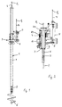
- a telescopic drill or Kelly rod 1 with itself known structure contains an inner tube 2, for example, which can also be a rod (see Fig. 2), on the Upper end of a Kelly eye 3 for attaching a suspension cable 4 and a drilling tool 5 is attached to the lower end thereof.
- the inner tube 2 is in a middle tube 6 through (not shown) Carrier strips guided axially and at the same time rotatably mounted and thus in a known Way telescopic.
- the middle tube 6 is in turn an outer tube 7 added in the same way.
- the outer Tube 7 is in one pass of a power head 8 of a rotary drive 9 axially displaceably received and over a driver ring 10 of the rotary head 8 and associated Driver strips on the circumference of the outer tube 7 in rotation drivable.
- the power turret 8 is by means of a gear slide 11 on a mast 12 (see Fig. 3) of a rotary drilling machine 13 slidably mounted and by means of a rope 14 and a winch 15 over the length of the mast 12 can be moved up and down.
- the 12 is on a movable Equipment carrier 16 stored a cabin 17 for an operator having.
- the individual tubes 2, 6, 7 have upper and lower end stops on who move or telescopic limit their relative axial movements.
- two pipes each via the rotary drive Locks can be snapped into place so that the Tubes axially fixed to each other and to the rotary head 8 are and an axial drilling force on the drill pipe (the Kelly rod 1) can be applied.
- the latches can rotate in a known manner be solved again.
- the support rope 4 and an associated winch 18 can the boring or Kelly bar 1 are raised and lowered.
- the feed rope 14 (alternatively with a hydraulic Feed cylinder), the power turret 8 can be raised and with the feed movement when drilling together with the boring bar 1 can be lowered.
- respective force measuring devices or sensors (not shown) are provided which deliver a respective tensile force signal to a comparison device.
- FIG. 4 is a rotary drilling machine with a hydraulic cylinder as a holding or feed device for the rotary head 8 shown.
- the following considerations of forces apply for both cylinders and winches as feed devices.
- the Simplification only the weight of pipes 2, 6 and 7 i.e. H. without the weight of the drilling tool, the power turret or the like.
- Fig. 2 shows damping device mounted on the power turret 8 with springs 21. On the springs 21 can measuring devices be attached for force detection. Especially simply by measuring the distance in proportion to the force or by Piezo force transducers or the like performed the measurement become.
- F R1 , F R2 and F R3 denote the weight of the inner, middle and outer tubes 2, 6 and 7, respectively (see FIG. 4).
- the tensile force F 1 is compared with the stored weight forces F R1 , F R2 and F R3 , taking into account the stroke path of the suspension cable 4, with normal operation during a first stroke path which is proportional to the length of the inner tube 2, and the above-mentioned force relationships will occur during the further stroke distances. If the measured force values F 1 deviate from the permissible, calculated force values by more than a certain force value, as can occur when two pipes are jammed, the comparison device generates a signal.
- This signal is shown, for example, in the cabin 17 of the equipment carrier 16 as a warning signal, for example as a visual display or as an acoustic warning signal, so that the operator can initiate an action in good time. For example, it can stop lifting and lower the jammed pipes by lowering it. However, the signal can also be operated by a control which stops the lifting of the boring bar by itself.
- the position of the power turret can be determined by measuring the distance on the cable 14 8 on the mast 12 and thus the starting position of the Boring bar 1 can be determined when pulling up and a zero setting for the suspension cable 4 at the start of lifting be made. It can therefore be used at any height position of the rotary drive 9 on the mast 12 made this method that the position deviation of the rotary drive from the zero position when measuring the rope travel on rope 4 is taken into account, i.e. added or subtracted depending on the direction becomes.
Landscapes
- Engineering & Computer Science (AREA)
- Life Sciences & Earth Sciences (AREA)
- Geology (AREA)
- Mining & Mineral Resources (AREA)
- Mechanical Engineering (AREA)
- Physics & Mathematics (AREA)
- Environmental & Geological Engineering (AREA)
- Fluid Mechanics (AREA)
- General Life Sciences & Earth Sciences (AREA)
- Geochemistry & Mineralogy (AREA)
- Earth Drilling (AREA)
Applications Claiming Priority (2)
| Application Number | Priority Date | Filing Date | Title |
|---|---|---|---|
| DE19813902 | 1998-03-28 | ||
| DE19813902A DE19813902C1 (de) | 1998-03-28 | 1998-03-28 | Verfahren zum Überwachen einer teleskopierbaren Bohrstange beim Hochziehen ihrer auseinandergezogenen Rohre und Schutzvorrichtung für eine teleskopierbare Bohrstange |
Publications (3)
| Publication Number | Publication Date |
|---|---|
| EP0947664A2 true EP0947664A2 (fr) | 1999-10-06 |
| EP0947664A3 EP0947664A3 (fr) | 2000-12-06 |
| EP0947664B1 EP0947664B1 (fr) | 2004-08-25 |
Family
ID=7862770
Family Applications (1)
| Application Number | Title | Priority Date | Filing Date |
|---|---|---|---|
| EP99104296A Expired - Lifetime EP0947664B1 (fr) | 1998-03-28 | 1999-03-03 | Procédé de controle d'une tige de forage télescopique et dispositif de protection d'une tige de forage télescopique |
Country Status (3)
| Country | Link |
|---|---|
| EP (1) | EP0947664B1 (fr) |
| AT (1) | ATE274634T1 (fr) |
| DE (2) | DE19813902C1 (fr) |
Cited By (10)
| Publication number | Priority date | Publication date | Assignee | Title |
|---|---|---|---|---|
| EP1580398A1 (fr) | 2004-03-23 | 2005-09-28 | BAUER Maschinen GmbH | Appareil et méthode pour constructions souterraines |
| ITTO20100436A1 (it) * | 2010-05-25 | 2011-11-26 | Soilmec Spa | Asta telescopica (kelly) per la realizzazione di pali trivellati. |
| EP3287588A1 (fr) * | 2016-08-24 | 2018-02-28 | BAUER Maschinen GmbH | Machine de travail et procédé destiné au travail d'un sol |
| CN109138971A (zh) * | 2018-09-28 | 2019-01-04 | 徐州徐工基础工程机械有限公司 | 钻杆操作提示方法及系统 |
| CN112780175A (zh) * | 2020-12-28 | 2021-05-11 | 湖北首开机械有限公司 | 安全钻孔装置 |
| CN112855048A (zh) * | 2021-03-08 | 2021-05-28 | 中煤科工集团重庆研究院有限公司 | 一种辅助上下钻杆装置用多级伸缩机构 |
| EP3882398A1 (fr) * | 2020-03-17 | 2021-09-22 | BAUER Maschinen GmbH | Tige de forage et procédé pour mise à niveau d'un agencement de tige carrée |
| EP3907371A1 (fr) * | 2020-05-07 | 2021-11-10 | BAUER Maschinen GmbH | Machine de travail et procédé de traitement d'un sol |
| CN117005845A (zh) * | 2023-06-30 | 2023-11-07 | 江苏徐工工程机械研究院有限公司 | 旋挖钻机分段式恒对地压力钻进方法、系统及旋挖钻机 |
| CN118757136A (zh) * | 2024-09-05 | 2024-10-11 | 山河智能装备股份有限公司 | 一种机锁钻杆控制方法、监控模拟系统及工程机械 |
Families Citing this family (7)
| Publication number | Priority date | Publication date | Assignee | Title |
|---|---|---|---|---|
| DE10116342C2 (de) * | 2001-04-02 | 2003-02-27 | Bauer Maschinen Gmbh | Hubwinde |
| DE10243744B4 (de) | 2002-09-20 | 2006-10-12 | Bauer Maschinen Gmbh | Verschiebevorrichtung und Baumaschine mit Verschiebevorrichtung |
| DE102012019850A1 (de) * | 2012-10-10 | 2014-04-10 | Liebherr-Werk Nenzing Gmbh | Verfahren und Vorrichtung zur Überwachung eines Bohrgestänges |
| DE102014109918A1 (de) | 2014-07-15 | 2016-01-21 | Bauer Maschinen Gmbh | Baumaschine und Verfahren zum Steuern einer Baumaschine |
| CN110300834B (zh) | 2017-01-18 | 2022-04-29 | 米尼克斯Crc有限公司 | 一种移动式连续油管钻井装置 |
| DE102017002675A1 (de) * | 2017-03-20 | 2018-09-20 | Liebherr-Werk Nenzing Gmbh | Verfahren zum Bestimmen der Geometrie einer teleskopierbaren Kellystange |
| DE102017002674A1 (de) * | 2017-03-20 | 2018-09-20 | Liebherr-Werk Nenzing Gmbh | Arbeitsmaschine zum Durchführen von Bohrarbeiten |
Family Cites Families (2)
| Publication number | Priority date | Publication date | Assignee | Title |
|---|---|---|---|---|
| US5630477A (en) * | 1995-06-02 | 1997-05-20 | Minatre William H | Downcrowdable telescopic augering apparatus |
| DE19626223C2 (de) * | 1996-06-29 | 2000-08-10 | Klemm Bohrtech | Kellystangen-Bohrvorrichtung |
-
1998
- 1998-03-28 DE DE19813902A patent/DE19813902C1/de not_active Expired - Fee Related
-
1999
- 1999-03-03 DE DE59910317T patent/DE59910317D1/de not_active Expired - Lifetime
- 1999-03-03 EP EP99104296A patent/EP0947664B1/fr not_active Expired - Lifetime
- 1999-03-03 AT AT99104296T patent/ATE274634T1/de not_active IP Right Cessation
Non-Patent Citations (1)
| Title |
|---|
| None |
Cited By (20)
| Publication number | Priority date | Publication date | Assignee | Title |
|---|---|---|---|---|
| EP1580398A1 (fr) | 2004-03-23 | 2005-09-28 | BAUER Maschinen GmbH | Appareil et méthode pour constructions souterraines |
| ITTO20100436A1 (it) * | 2010-05-25 | 2011-11-26 | Soilmec Spa | Asta telescopica (kelly) per la realizzazione di pali trivellati. |
| EP2390458A1 (fr) | 2010-05-25 | 2011-11-30 | Soilmec S.p.A. | Installation de forage avec tiges d'entraînement télescopiques |
| US11473375B2 (en) | 2016-08-24 | 2022-10-18 | Bauer Maschinen Gmbh | Working machine and method for working the ground |
| EP3287588A1 (fr) * | 2016-08-24 | 2018-02-28 | BAUER Maschinen GmbH | Machine de travail et procédé destiné au travail d'un sol |
| WO2018036713A1 (fr) * | 2016-08-24 | 2018-03-01 | Bauer Maschinen Gmbh | Machine de travail et procédé de traitement d'un sol |
| CN109563731A (zh) * | 2016-08-24 | 2019-04-02 | 包尔机械有限公司 | 工作机械以及用于处理地面的方法 |
| RU2722612C1 (ru) * | 2016-08-24 | 2020-06-02 | Бауэр Машинен Гмбх | Рабочая машина и способ обработки грунта |
| CN109563731B (zh) * | 2016-08-24 | 2021-04-13 | 包尔机械有限公司 | 工作机械以及用于处理地面的方法 |
| CN109138971A (zh) * | 2018-09-28 | 2019-01-04 | 徐州徐工基础工程机械有限公司 | 钻杆操作提示方法及系统 |
| CN109138971B (zh) * | 2018-09-28 | 2023-12-05 | 徐州徐工基础工程机械有限公司 | 钻杆操作提示方法及系统 |
| EP3882398A1 (fr) * | 2020-03-17 | 2021-09-22 | BAUER Maschinen GmbH | Tige de forage et procédé pour mise à niveau d'un agencement de tige carrée |
| WO2021185499A1 (fr) * | 2020-03-17 | 2021-09-23 | Bauer Maschinen Gmbh | Tige de forage et procédé de rénovation d'un agencement de tige carrée |
| US11927059B2 (en) | 2020-03-17 | 2024-03-12 | Bauer Maschinen Gmbh | Drill rod and method for retrofitting a Kelly bar arrangement |
| EP3907371A1 (fr) * | 2020-05-07 | 2021-11-10 | BAUER Maschinen GmbH | Machine de travail et procédé de traitement d'un sol |
| WO2021224168A1 (fr) * | 2020-05-07 | 2021-11-11 | Bauer Maschinen Gmbh | Machine de travail et procédé de travail de la terre |
| CN112780175A (zh) * | 2020-12-28 | 2021-05-11 | 湖北首开机械有限公司 | 安全钻孔装置 |
| CN112855048A (zh) * | 2021-03-08 | 2021-05-28 | 中煤科工集团重庆研究院有限公司 | 一种辅助上下钻杆装置用多级伸缩机构 |
| CN117005845A (zh) * | 2023-06-30 | 2023-11-07 | 江苏徐工工程机械研究院有限公司 | 旋挖钻机分段式恒对地压力钻进方法、系统及旋挖钻机 |
| CN118757136A (zh) * | 2024-09-05 | 2024-10-11 | 山河智能装备股份有限公司 | 一种机锁钻杆控制方法、监控模拟系统及工程机械 |
Also Published As
| Publication number | Publication date |
|---|---|
| EP0947664B1 (fr) | 2004-08-25 |
| EP0947664A3 (fr) | 2000-12-06 |
| DE59910317D1 (de) | 2004-09-30 |
| ATE274634T1 (de) | 2004-09-15 |
| DE19813902C1 (de) | 1999-06-17 |
Similar Documents
| Publication | Publication Date | Title |
|---|---|---|
| EP0947664B1 (fr) | Procédé de controle d'une tige de forage télescopique et dispositif de protection d'une tige de forage télescopique | |
| DE102010020016B4 (de) | Kran und Verfahren zum Aufrichten des Krans | |
| EP4172096B1 (fr) | Procédé de construction d'une installation d'ascenseur et installation d'ascenseur | |
| DE2615086A1 (de) | Vorrichtung zum handhaben von bohrfutterrohren | |
| EP0235585A1 (fr) | Déchargeur pour silo avec gouttière télescopique de descente dans le silo | |
| DE3642387C2 (fr) | ||
| DE202018105169U1 (de) | Verfahrbarer Personenlift | |
| DE102015115146A1 (de) | Baumaschine und Verfahren zum Auf- und Abbewegen eines Hubelementes | |
| DE102019130562A1 (de) | Teleskopische Hubeinheit | |
| DE102012019850A1 (de) | Verfahren und Vorrichtung zur Überwachung eines Bohrgestänges | |
| DE2542012C3 (de) | Vorrichtung zum Eintreiben eines Rammpfahles | |
| DE19512070C2 (de) | Bohrgerät | |
| DE3018560C2 (fr) | ||
| DE102011052183A1 (de) | Hebewerk | |
| DE2001060B2 (de) | Stellungsanzeigeeinnchtung fur den Abstellkopf eines in einem Bohr turm angeordneten Abstellgerates fur Rohrzuge | |
| DE19512109C2 (de) | Bohrgerät | |
| DE4038424C1 (en) | Kelly borehole drilling arrangement - involves telescopically nested pipes connected to drill head | |
| DE19626223C2 (de) | Kellystangen-Bohrvorrichtung | |
| DE2212876A1 (de) | Teleskopstange fuer Maschine fuer Gruendungsarbeiten | |
| DE2328740A1 (de) | Ueberladungsschutzvorrichtung fuer einen aufzug | |
| DE102005029595B4 (de) | Bohrgerät mit einem Mast und einer daran verschiebbaren Konsole für ein Bohrgestänge | |
| DE2433015B2 (de) | Hebevorrichtung mit einem vertikal festlegbaren mast | |
| WO2021224168A1 (fr) | Machine de travail et procédé de travail de la terre | |
| EP3879034B1 (fr) | Agencement de chariot pour une machine de construction et procédé associé | |
| DE112014004373T5 (de) | Vorrichtung zum Steuern einer Bremse einer Trommel eines Hebewerks einer Bohranlage und Verfahren zum Steuern einer solchen Vorrichtung |
Legal Events
| Date | Code | Title | Description |
|---|---|---|---|
| PUAI | Public reference made under article 153(3) epc to a published international application that has entered the european phase |
Free format text: ORIGINAL CODE: 0009012 |
|
| AK | Designated contracting states |
Kind code of ref document: A2 Designated state(s): AT DE FR IT |
|
| AX | Request for extension of the european patent |
Free format text: AL;LT;LV;MK;RO;SI |
|
| PUAL | Search report despatched |
Free format text: ORIGINAL CODE: 0009013 |
|
| RIC1 | Information provided on ipc code assigned before grant |
Free format text: 7E 21B 17/07 A, 7E 21B 19/08 B |
|
| AK | Designated contracting states |
Kind code of ref document: A3 Designated state(s): AT BE CH CY DE DK ES FI FR GB GR IE IT LI LU MC NL PT SE |
|
| AX | Request for extension of the european patent |
Free format text: AL;LT;LV;MK;RO;SI |
|
| 17P | Request for examination filed |
Effective date: 20001201 |
|
| AKX | Designation fees paid |
Free format text: AT DE FR IT |
|
| RAP1 | Party data changed (applicant data changed or rights of an application transferred) |
Owner name: BAUER MASCHINEN GMBH |
|
| 17Q | First examination report despatched |
Effective date: 20031118 |
|
| GRAP | Despatch of communication of intention to grant a patent |
Free format text: ORIGINAL CODE: EPIDOSNIGR1 |
|
| GRAS | Grant fee paid |
Free format text: ORIGINAL CODE: EPIDOSNIGR3 |
|
| GRAA | (expected) grant |
Free format text: ORIGINAL CODE: 0009210 |
|
| AK | Designated contracting states |
Kind code of ref document: B1 Designated state(s): AT DE FR IT |
|
| REF | Corresponds to: |
Ref document number: 59910317 Country of ref document: DE Date of ref document: 20040930 Kind code of ref document: P |
|
| ET | Fr: translation filed | ||
| PLBE | No opposition filed within time limit |
Free format text: ORIGINAL CODE: 0009261 |
|
| STAA | Information on the status of an ep patent application or granted ep patent |
Free format text: STATUS: NO OPPOSITION FILED WITHIN TIME LIMIT |
|
| 26N | No opposition filed |
Effective date: 20050526 |
|
| PGFP | Annual fee paid to national office [announced via postgrant information from national office to epo] |
Ref country code: AT Payment date: 20070323 Year of fee payment: 9 |
|
| PG25 | Lapsed in a contracting state [announced via postgrant information from national office to epo] |
Ref country code: AT Free format text: LAPSE BECAUSE OF NON-PAYMENT OF DUE FEES Effective date: 20080303 |
|
| REG | Reference to a national code |
Ref country code: FR Ref legal event code: PLFP Year of fee payment: 18 |
|
| REG | Reference to a national code |
Ref country code: FR Ref legal event code: PLFP Year of fee payment: 19 |
|
| REG | Reference to a national code |
Ref country code: FR Ref legal event code: PLFP Year of fee payment: 20 |
|
| PGFP | Annual fee paid to national office [announced via postgrant information from national office to epo] |
Ref country code: IT Payment date: 20180322 Year of fee payment: 20 Ref country code: FR Payment date: 20180326 Year of fee payment: 20 |
|
| PGFP | Annual fee paid to national office [announced via postgrant information from national office to epo] |
Ref country code: DE Payment date: 20180328 Year of fee payment: 20 |
|
| REG | Reference to a national code |
Ref country code: DE Ref legal event code: R071 Ref document number: 59910317 Country of ref document: DE |