EP0947694A2 - Soupape de contrÔle pour un compresseur en plateau en biais à capacité variable - Google Patents
Soupape de contrÔle pour un compresseur en plateau en biais à capacité variable Download PDFInfo
- Publication number
- EP0947694A2 EP0947694A2 EP99106498A EP99106498A EP0947694A2 EP 0947694 A2 EP0947694 A2 EP 0947694A2 EP 99106498 A EP99106498 A EP 99106498A EP 99106498 A EP99106498 A EP 99106498A EP 0947694 A2 EP0947694 A2 EP 0947694A2
- Authority
- EP
- European Patent Office
- Prior art keywords
- drive shaft
- valve
- valve body
- passage
- variable displacement
- Prior art date
- Legal status (The legal status is an assumption and is not a legal conclusion. Google has not performed a legal analysis and makes no representation as to the accuracy of the status listed.)
- Withdrawn
Links
Images






Classifications
-
- F—MECHANICAL ENGINEERING; LIGHTING; HEATING; WEAPONS; BLASTING
- F04—POSITIVE - DISPLACEMENT MACHINES FOR LIQUIDS; PUMPS FOR LIQUIDS OR ELASTIC FLUIDS
- F04B—POSITIVE-DISPLACEMENT MACHINES FOR LIQUIDS; PUMPS
- F04B27/00—Multi-cylinder pumps specially adapted for elastic fluids and characterised by number or arrangement of cylinders
- F04B27/08—Multi-cylinder pumps specially adapted for elastic fluids and characterised by number or arrangement of cylinders having cylinders coaxial with, or parallel or inclined to, main shaft axis
- F04B27/14—Control
- F04B27/16—Control of pumps with stationary cylinders
- F04B27/18—Control of pumps with stationary cylinders by varying the relative positions of a swash plate and a cylinder block
- F04B27/1804—Controlled by crankcase pressure
-
- F—MECHANICAL ENGINEERING; LIGHTING; HEATING; WEAPONS; BLASTING
- F04—POSITIVE - DISPLACEMENT MACHINES FOR LIQUIDS; PUMPS FOR LIQUIDS OR ELASTIC FLUIDS
- F04B—POSITIVE-DISPLACEMENT MACHINES FOR LIQUIDS; PUMPS
- F04B27/00—Multi-cylinder pumps specially adapted for elastic fluids and characterised by number or arrangement of cylinders
- F04B27/08—Multi-cylinder pumps specially adapted for elastic fluids and characterised by number or arrangement of cylinders having cylinders coaxial with, or parallel or inclined to, main shaft axis
- F04B27/10—Multi-cylinder pumps specially adapted for elastic fluids and characterised by number or arrangement of cylinders having cylinders coaxial with, or parallel or inclined to, main shaft axis having stationary cylinders
- F04B27/1036—Component parts, details, e.g. sealings, lubrication
-
- F—MECHANICAL ENGINEERING; LIGHTING; HEATING; WEAPONS; BLASTING
- F04—POSITIVE - DISPLACEMENT MACHINES FOR LIQUIDS; PUMPS FOR LIQUIDS OR ELASTIC FLUIDS
- F04B—POSITIVE-DISPLACEMENT MACHINES FOR LIQUIDS; PUMPS
- F04B39/00—Component parts, details, or accessories, of pumps or pumping systems specially adapted for elastic fluids, not otherwise provided for in, or of interest apart from, groups F04B25/00 - F04B37/00
- F04B39/10—Adaptations or arrangements of distribution members
- F04B39/1006—Adaptations or arrangements of distribution members the members being ball valves
-
- F—MECHANICAL ENGINEERING; LIGHTING; HEATING; WEAPONS; BLASTING
- F04—POSITIVE - DISPLACEMENT MACHINES FOR LIQUIDS; PUMPS FOR LIQUIDS OR ELASTIC FLUIDS
- F04B—POSITIVE-DISPLACEMENT MACHINES FOR LIQUIDS; PUMPS
- F04B27/00—Multi-cylinder pumps specially adapted for elastic fluids and characterised by number or arrangement of cylinders
- F04B27/08—Multi-cylinder pumps specially adapted for elastic fluids and characterised by number or arrangement of cylinders having cylinders coaxial with, or parallel or inclined to, main shaft axis
- F04B27/14—Control
- F04B27/16—Control of pumps with stationary cylinders
- F04B27/18—Control of pumps with stationary cylinders by varying the relative positions of a swash plate and a cylinder block
- F04B27/1804—Controlled by crankcase pressure
- F04B2027/1822—Valve-controlled fluid connection
- F04B2027/1827—Valve-controlled fluid connection between crankcase and discharge chamber
-
- F—MECHANICAL ENGINEERING; LIGHTING; HEATING; WEAPONS; BLASTING
- F04—POSITIVE - DISPLACEMENT MACHINES FOR LIQUIDS; PUMPS FOR LIQUIDS OR ELASTIC FLUIDS
- F04B—POSITIVE-DISPLACEMENT MACHINES FOR LIQUIDS; PUMPS
- F04B27/00—Multi-cylinder pumps specially adapted for elastic fluids and characterised by number or arrangement of cylinders
- F04B27/08—Multi-cylinder pumps specially adapted for elastic fluids and characterised by number or arrangement of cylinders having cylinders coaxial with, or parallel or inclined to, main shaft axis
- F04B27/14—Control
- F04B27/16—Control of pumps with stationary cylinders
- F04B27/18—Control of pumps with stationary cylinders by varying the relative positions of a swash plate and a cylinder block
- F04B27/1804—Controlled by crankcase pressure
- F04B2027/184—Valve controlling parameter
- F04B2027/1859—Suction pressure
-
- F—MECHANICAL ENGINEERING; LIGHTING; HEATING; WEAPONS; BLASTING
- F04—POSITIVE - DISPLACEMENT MACHINES FOR LIQUIDS; PUMPS FOR LIQUIDS OR ELASTIC FLUIDS
- F04B—POSITIVE-DISPLACEMENT MACHINES FOR LIQUIDS; PUMPS
- F04B27/00—Multi-cylinder pumps specially adapted for elastic fluids and characterised by number or arrangement of cylinders
- F04B27/08—Multi-cylinder pumps specially adapted for elastic fluids and characterised by number or arrangement of cylinders having cylinders coaxial with, or parallel or inclined to, main shaft axis
- F04B27/14—Control
- F04B27/16—Control of pumps with stationary cylinders
- F04B27/18—Control of pumps with stationary cylinders by varying the relative positions of a swash plate and a cylinder block
- F04B27/1804—Controlled by crankcase pressure
- F04B2027/1863—Controlled by crankcase pressure with an auxiliary valve, controlled by
- F04B2027/1877—External parameters
-
- Y—GENERAL TAGGING OF NEW TECHNOLOGICAL DEVELOPMENTS; GENERAL TAGGING OF CROSS-SECTIONAL TECHNOLOGIES SPANNING OVER SEVERAL SECTIONS OF THE IPC; TECHNICAL SUBJECTS COVERED BY FORMER USPC CROSS-REFERENCE ART COLLECTIONS [XRACs] AND DIGESTS
- Y10—TECHNICAL SUBJECTS COVERED BY FORMER USPC
- Y10T—TECHNICAL SUBJECTS COVERED BY FORMER US CLASSIFICATION
- Y10T137/00—Fluid handling
- Y10T137/0971—Speed responsive valve control
- Y10T137/1044—With other condition responsive valve control
-
- Y—GENERAL TAGGING OF NEW TECHNOLOGICAL DEVELOPMENTS; GENERAL TAGGING OF CROSS-SECTIONAL TECHNOLOGIES SPANNING OVER SEVERAL SECTIONS OF THE IPC; TECHNICAL SUBJECTS COVERED BY FORMER USPC CROSS-REFERENCE ART COLLECTIONS [XRACs] AND DIGESTS
- Y10—TECHNICAL SUBJECTS COVERED BY FORMER USPC
- Y10T—TECHNICAL SUBJECTS COVERED BY FORMER US CLASSIFICATION
- Y10T137/00—Fluid handling
- Y10T137/0971—Speed responsive valve control
- Y10T137/108—Centrifugal mass type [exclusive of liquid]
- Y10T137/1135—Rotating valve and rotating governor
Definitions
- the present invention relates to variable displacement compressors employed in automotive air conditioning systems.
- a typical variable displacement compressor has a housing that houses a crank chamber and supports a rotatable driving shaft. Cylinder bores extend through a cylinder block, which forms part of the housing. A piston is accommodated in each cylinder bore. A swash plate is supported to rotate integrally with the drive shaft, while inclining in the axial direction. Rotation of the swash plate reciprocates each piston and draws refrigerant gas into the associated cylinder bore, compresses the refrigerant gas, and disharges the compressed refrigerant gas into a discharge chamber.
- a displacement control valve adjusts the difference between the pressure of the cylinder bores and the pressure of the crank chamber (first differential pressure ⁇ P1) to alter the inclination of the swash plate with respect to a plane perpendicular to the drive shaft.
- the stroke of the pistons is changed in accordance with the inclination of the swash plate to vary the displacement of the compressor.
- variable displacement compressor is connected to an automotive engine by an electromagnetic clutch.
- the clutch is actuated to connect the engine to the compressor when activating the air conditioning system.
- Compressors that continue operation during acceleration of the vehicle are also known. However, such compressors interfere with acceleration and lower fuel consumption.
- United States Patent No. 4,872,814 proposes a variable displacement compressor that overcomes these shortcomings.
- the compressor has a displacement shifting mechanism that shifts displacement from a maximum state toward a minimum state when the rotating speed becomes too high.
- the displacement shifting mechanism includes a pressurizing passage 101 that connects a crank chamber with a discharge chamber (neither shown).
- a valve body 102 is attached to a drive shaft 103 by means of springs 105, 106 to rotate integrally with the drive shaft 103.
- the pressurizing passage 101 has a port 104. As shown by the chain lines in Fig.
- valve body 102 moves relative to the drive shaft 103 in a direction parallel to the axis L of the drive shaft 103 and in a direction perpendicular to the axis L. Movement of the valve body 102 in these two directions opens and closes the port 104 with the valve body 102. Under normal conditions, the forces of the springs 105, 106 cause the valve body 102 to close the port 104.
- the valve body 102 is arranged in a crank pressure region 101a, which is located downstream of the port 104 in the pressurizing passage 101.
- the valve body 102 includes a weight 102a.
- Nc a predetermined limit value which is shown in Fig. 19
- the centrifugal force applied to the weight 102a moves the valve body 102 against the force of the spring 105 in a direction perpendicular to axis L and opens the port 104.
- the port 104 is opened, the refrigerant gas in the discharge chamber enters the crank chamber through the pressurizing passage 101 and increases the pressure of the crank chamber. Consequently, the first differential pressure ⁇ P1 increases and decreases the displacement of the compressor. This decreases compression load and avoids excessive friction of the moving parts.
- the pressure of the discharge chamber becomes abnormally high.
- the difference between the pressure of the discharge chamber and the pressure of the crank pressure region 101 (second differential pressure ⁇ P2) exceeds a predetermined limit value ⁇ Pc
- the discharge pressure communicated through the port 104 moves the valve body 102 toward the drive shaft 103 against the pressure of the crank pressure region and the force of the spring 106 to open the port 104.
- the refrigerant gas in the discharge chamber enters the crank chamber through the pressurizing passage 101 and increases the pressure of the crank chamber. This decreases the displacement of the compressor.
- the compression load decreases and reduces friction in moving parts.
- the refrigerant gas in the discharge chamber is drawn into the crank chamber to increase the pressure of the crank chamber and decrease the displacement of the compressor when the rotating speed N of the drive shaft 103 exceeds a predetermined limit value Nc or when the second differential pressure ⁇ P2 exceeds the predetermined limit value ⁇ Pc.
- variable displacement compressor that performs smooth compression and operates the compressor efficiently.
- the present invention provides a variable displacement compressor including a drive shaft rotated about its axis and a compression mechanism for drawing in and compressing gas in accordance with the rotation of the drive shaft.
- the compression mechanism includes a drive plate supported on the drive shaft.
- the drive plate inclines between a maximum inclination position, at which the displacement of the compressor is maximum, and a minimum inclination position, at which the compressor displacement is minimum.
- a crank chamber houses part of the compression mechanism. The gas flows into and out of the crank chamber to vary the displacement in accordance with the pressure of the gas in the crank chamber. The inclination of the drive plate is decreased as the pressure of the crank chamber increases.
- the compressor further includes a suction pressure region, which is exposed to the gas drawn into the compressor by the compression mechanism, a discharge pressure region, which is exposed to the gas compressed by the compression mechanism, a first passage that increases the pressure of the crank chamber by permitting the flow of the gas from the discharge pressure region to the crank chamber, a second passage that decreases the pressure of the crank chamber by permitting the flow of the gas from the crank chamber to the suction pressure region, and a valve arranged to open or close a port, which is in either the first passage or the second passage.
- the valve adjusts the opened area of the port to increase the pressure of the crank chamber when the rotating speed of the drive shaft exceeds a predetermined value.
- a mechanism regulates the minimum inclination position of the drive plate such that the minimum displacement is about 30% to 60% of the maximum displacement.
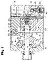
- a variable displacement compressor according to a first embodiment of the present invention will now be described with reference to Figs. 1 to 6.
- a front housing 11 is fixed to the front end of a cylinder block 12, while a rear housing 13 is fixed to the rear end of the cylinder block 12 with a valve plate 14 arranged in between.
- a compressor housing is defined by the front housing 11, the cylinder block 12, and the rear housing 13.
- the rear housing 13 houses a suction chamber 38, which defines a suction pressure region, and a discharge chamber 39, which defines a discharge pressure region.
- the valve plate 14 includes suction ports 40, suction flaps 41, discharge ports 42, and discharge flaps 43.
- a crank chamber 15 is defined in the front housing 11 in front of the cylinder block 12.
- a drive shaft 16 extends through the crank chamber 15 between the front housing 11 and the cylinder block 12. The drive shaft 16 is rotatably supported by radial bearings 20 and 27.
- a rotor 19 is fixed to the drive shaft 16.
- a drive plate, or swash plate 21, which functions as a cam plate, is fitted to the drive shaft 16.
- the swash plate 21 is supported such that it inclines as it slides along the drive shaft 16.
- a hinge mechanism 25 connects the swash plate 21 to the rotor 19.
- the hinge mechanism 25 rotates the swash plate 21 integrally with the drive shaft 16 while guiding the inclining motion of the swash plate 21.
- the swash plate 21 is located at a maximum inclination position and the displacement is thus maximum.
- the minimum inclination position of the swash plate 21 is set so that the displacement is 50% of that when the swash plate 21 is located at the maximum displacement position.
- the snap ring 23 and the rotor 19 serve as stoppers that limit the movement of the swash plate 21.
- Cylinder bores 31 extend through the cylinder block 12.
- a piston 32 is accommodated in each cylinder bore.
- Each piston 32 has a head 32a and an opposing skirt 32b.
- Each skirt 32b is coupled to the peripheral portion of the swash plate 21 by a pair of shoes 33.
- a compression reaction force produced by the compression motion of the pistons 32 is received by the front housing 11 by way of the shoes 33, the swash plate 21, the hinge mechanism 25, the rotor 19, and a thrust bearing 45.
- a bleeding passage 47 extends between the crank chamber 15 and the suction chamber 38 through the cylinder block 12 and the valve plate 14.
- the bleeding passage 47 is located between a pair of adjacent cylinder bores 31.
- a supply passage 48 and a pressurizing passage 55 independently connect the discharge chamber 39 and the crank chamber 15.
- a displacement control valve 49 is arranged in the supply passage 48.
- the control valve 49 has a diaphragm 49a, a valve body 49b, and a valve hole 49c.
- the diaphragm 49a adjusts the opening size of the valve hole 49c by regulating the position of the valve body 49b.
- Suction pressure Ps is communicated through a pressure sensing passage 50 and is applied to the diaphragm 49a to adjust the opening size of the valve hole 49c with the valve body 49b.
- the control valve 49 adjusts the amount of refrigerant gas drawn into the crank chamber 15 from the discharge chamber 39 through the supply passage 48 to control the first differential pressure ⁇ P1, which is the difference between the crank chamber pressure Pc acting on the skirt side of the pistons 32, and the pressure Pb of the cylinder bores 31 acting on the head side of the pistons 32.
- the inclination of the swash plate 21 is varied in accordance with the first differential pressure ⁇ P1. This changes the stroke of the pistons 32 and varies the displacement.
- a central bore 51 extends through the cylinder block 12.
- a conduit 14a extends through the valve plate 14 between the discharge chamber 39 and the central bore 51.
- the pressurizing passage 55 includes the conduit 14a, the central bore 51, and the spaces formed in the radial bearing 27.
- the high-pressure refrigerant gas in the discharge chamber 39 is sent into the crank chamber 15 through the pressurizing passage 55 to increase the crank chamber pressure Pc. This increases the first differential pressure ⁇ P1 and decreases the displacement.
- a valve chamber 52 is defined in the central bore 51.
- a valve V is accommodated in the valve chamber 52 to selectively open and close the pressurizing passage 55.
- the valve V opens the pressurizing passage 55 when the rotating speed N of the drive shaft 16 exceeds a predetermined limit value Nc and closes the pressurizing passage 55 when the speed N is equal to or lower than the limit value Nc.
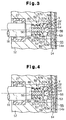
- the valve V includes a valve seat 53, which serves as a fixed guide.
- the valve seat 53 is fixed to the valve plate 14 in the valve chamber 52.
- a valve port 54 which is aligned with the drive shaft axis L, extends through the valve seat 53.
- the valve chamber 52 is connected to the discharge chamber 39 through the valve port 54 and the conduit 14a.
- the valve seat 53 has a fixed guide surface 53a, which faces a rear end face 16a of the drive shaft 16.
- the fixed guide surface 53a is flat and annular.
- the valve port 54 extends through the center of the fixed guide surface 53a.
- the inner portion of the fixed guide surface 53a is stepped toward the valve plate 14.
- a connecting rod 56 projects from the rear end face 16a of the drive shaft 16 along the axis L.
- the connecting rod 56 is coupled to a guide 57, which serves as a rotating member.
- Splines 56a extend axially along the connecting rod 56
- splines 57b extend axially along the guide 57.
- the splines 56a, 57b mesh with one another to rotate the guide 57 integrally with the drive shaft 16 while permitting axial movement of the guide 57.
- the guide 57 has a rotating guide surface 57a coaxial to the fixed guide surface 53a of the valve seat 53.
- the rotated guide surface 57a is tapered like the surface of a truncated cone. The greater the radius of a point on the rotated guide surface 57a, the closer that point is to the fixed guide surface 53a.
- a spherical valve body 58 is accommodated in the valve chamber 52.
- the valve body 58 moves along axis L to open or close the valve port 54. That is, the valve body 58 opens or closes the pressurizing passage 55 in the valve chamber 52, which is included in the crank chamber pressure region.
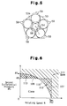
- a plurality of equally spaced orbiting elements, or orbiting balls 59 are arranged between the fixed guide surface 53a and the rotated guide surface 57a.
- the centers of the balls 59 are located on a circle, the center of which is the axis L.
- the angular spacing between any given ball 59 and the ball 59 furthest from the given ball 59 is 90° or greater.
- the balls 59 and the valve body 58 are identical. Thus, the diameter and material of the balls 59 and the valve body 58 are the same.
- a coil spring 60 is arranged between the rear end face 16a of the drive shaft 16 and a stepped portion 57c of the rotated guide 57 to urge the rotated guide 57 toward the valve seat 53.
- the balls 59 are held between the planar fixed guide surface 53a and the conical rotated guide surface 57a.
- the conical surface 57a forces the balls 59 toward axis L until the balls 59 contact the valve body 58.
- pressure is applied to the outer surface of the valve body 58 from several locations by the balls 59.
- the pressure is directed toward the center point O1 of the valve body 58.
- the center point O1 is located along axis L at a position that is rearward from contact points O2, which are the points of contact between the balls 59 and the valve body 58.
- the valve body 58 is urged to abut against the valve seat 53 to close the valve port 54.
- the drive shaft 16 is rotated by an external drive source such as an automotive engine.
- an external drive source such as an automotive engine.
- the rotor 19 and the hinge mechanism 25 rotate the drive shaft 21 integrally with the drive shaft 16.
- the rotation of the swash plate 21 is converted to linear reciprocation of the pistons 32 by means of the shoes 33.
- the reciprocation of each piston 32 causes the refrigerant gas in the suction chamber 38 to be drawn into the associated cylinder bore 31 through the suction port 40 and suction flap 41.
- the refrigerant gas is then compressed to a predetermined pressure value and discharged from the cylinder bore 31 into the discharge chamber 39 through the discharge port 42 and the discharge flap 43.
- the cooling load is great when the temperature in the passenger compartment is high.
- the suction pressure Ps in the suction chamber 38 is high.
- the first differential pressure ⁇ P1 (the difference between the pressure Pc of the crank chamber 15 and the pressure Pb of the cylinder bores 31) is small.
- ⁇ P1 the difference between the pressure Pc of the crank chamber 15 and the pressure Pb of the cylinder bores 31
- the high suction pressure Ps communicated through the pressure sensing passage 50 acts on the diaphragm 49a and keeps the valve hole 49c closed by the valve body 49b.
- the supply passage 48 is closed.
- the high-pressure refrigerant gas in the discharge chamber 39 therefore does not flow into the crank chamber 15.
- crank chamber pressure Pc is maintained at a satisfactory level regardless of the blow-by gas, which enables the compressor to continue operation in the maximum displacement state.
- the cooling load decreases.
- the low suction pressure Ps communicated through the pressure sensing passage 50 acts on the diaphragm 49a of the control valve 49.
- the diaphragm 49a deforms in accordance with the suction pressure Ps.
- the high-pressure refrigerant gas in the discharge chamber 39 flows into the crank chamber 15 through the supply passage 48.
- the flow rate of the refrigerant gas sent to the crank chamber 15 changes in accordance with the size of the valve hole 49c.
- the cooling load approaches a null state. This further decreases the suction pressure Ps of the suction chamber 38 and maximizes the size of the valve hole 49c of the control valve 49.
- the high-pressure refrigerant gas in the discharge chamber 39 is sent to the crank chamber 15 through the supply passage 48. This further increases the first differential pressure ⁇ P1 and moves the swash plate 21 to the minimum inclination position, as shown in the state of Fig. 2. This shortens the stroke of the pistons 32 and operates the compressor in a minimum displacement state (50% displacement).
- the cooling load increases.
- This increases the suction pressure Ps of the suction chamber 38.
- the increased suction pressure Ps communicated through the pressure sensing passage 50 acts on the diaphragm 49a of the control valve 49.
- the diaphragm 49a deforms in accordance with the suction pressure Ps.
- This moves the valve body 49b in a direction closing the valve hole 49c and causes the control valve 49 to decrease the size of the supply passage 48.
- the flow rate of the refrigerant gas sent to the crank chamber 15 from the discharge chamber 39 through the supply passage 48 decreases.
- the pressure Pc of the crank chamber 15 decreases thereby decreasing the first differential pressure ⁇ P1.
- the swash plate 21 moves toward the maximum inclination position in accordance with the first differential pressure ⁇ P1. This lengthens the stroke of the pistons 32 and increases the displacement.
- the suction pressure Ps of the suction chamber 38 increases.
- the high suction pressure Ps communicated through the pressure sensing passage 50, acts on the diaphragm 49a of the control valve 49 and closes the valve hole 49c, or the supply passage 48. This stops the flow of high-pressure refrigerant gas from the discharge chamber 39 to the crank chamber 15.
- the refrigerant gas in the crank chamber 15 then bleeds into the suction chamber 38 through the bleeding passage 47.
- This decreases the pressure Pc of the crank chamber 15 such that the difference between the crank chamber pressure Pc and the suction pressure Ps becomes small.
- the first differential pressure ⁇ P1 becomes small, which moves the swash plate 21 to the maximum inclination position. This lengthens the stroke of the pistons 32 and operates the compressor in a maximum displacement state (100% displacement).
- variable displacement compressor alters the pressure Pc of the crank chamber 15 with the control valve 49 in accordance with the cooling load, or suction pressure Ps, to ultimately maintain the suction pressure Ps at a constant suction pressure Ps.
- valve body 58 closes the valve port 54 and the pressurizing passage 55 when the drive shaft 16 is rotated under normal conditions.
- the guide 57 rotates integrally with the drive shaft 16.
- the rotated guide surface 57a rotates relative to the fixed guide surface 53a of the seat 53. Since the balls 59 are held between the guide surfaces 53a, 57a, the rotation of the guide 57 rolls the balls 59 about the axis L of the drive shaft 16. Centrifugal force acts on the rolling balls 59 in a direction that increases the orbital radius of the balls 59.
- the centrifugal force applied to the balls 59 is small. In such case, the force of the coil spring 60 urges the balls 59 toward the drive shaft axis L. The balls 59 abut against the valve body 58. This restricts movement of the balls 59 toward axis L and stabilizes the rolling motion of the balls 59 about axis L.
- the conical surface of the rotated guide surface 57a is tapered relative to axis L such as to counter the centrifugal force acting of the balls 59.
- the guide 57 receives a component force that urges the guide 57 in a direction countering the force of the spring 60 when centrifugal force acts on the balls 59. This offsets the force of the spring 60 and decreases the force applied to the valve body 58 that closes the valve port 54 compared to that when the drive shaft 16 is stationary. The closing force decreases as the rotating speed of the drive shaft 16 increases.
- the pressure of the discharge chamber 38 Pd becomes higher than the pressure Pc of the valve chamber 52 (the crank chamber pressure Pc and the pressure of the valve chamber 52 are the same). Accordingly, the difference between the pressure Pd of the discharge chamber 39 and the pressure Pc of the valve chamber 52, or the second differential pressure ⁇ P2, acts on the valve body 58 in a direction opening the valve port 54 during operation of the compressor.
- the force becomes greater if the rotating speed N of the drive shaft 16 increases, which causes an increase in the pressure Pd of the discharge chamber 39, or if the pressure Pd of the discharge chamber 39 is increased by insufficient cooling by the condenser (not shown).
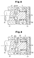
- Fig. 6 is a graph plotting predetermined limit values Nx of the drive shaft rotating speed N, which is represented by the horizontal axis, and predetermined limit values ⁇ Px of the second differential pressure ⁇ P2, which is represented by the vertical axis.
- predetermined limit values Nx of the drive shaft rotating speed N which is represented by the horizontal axis
- predetermined limit values ⁇ Px of the second differential pressure ⁇ P2 which is represented by the vertical axis.
- the rotating speed N of the drive shaft 16 that causes the valve body 58 to open the valve chamber port 54 becomes lower as the second differential pressure ⁇ P2 increases (i.e., as the pressure of the discharge chamber 39 increases).
- the second differential pressure ⁇ P2 that opens the valve V when the rotating speed N is null is defined as ⁇ P max
- N max the rotating speed N that opens the valve V when the second differential pressure ⁇ P2 is null.
- Limit values for determining whether the valve body 58 should be opened are plotted along a limit value curve 110, which connects ⁇ P max and N max .
- Zone 111 indicated by slanted lines (which includes the area 112 marked by rectangles), represents the range in which the valve V is opened.
- the zone on the other side of the curve 110 (which includes the area 113 marked by squares) represents the range in which the valve V is closed.
- valve body 58 When the valve body 58 opens the valve port 54, gas from the discharge chamber 39 is drawn into the crank chamber 15 through the pressurizing passage 55. This increases the pressure of the crank chamber 15, increases the first differential pressure ⁇ P1, and decreases the displacement. The decreased displacement decreases the compression load of the compressor and avoids early deterioration of the moving parts, such as the bearings 20, 27, 45, the seal 18, the swash plate 21, the shoes 33, and the pistons 32.
- a displacement control valve 61 is arranged in a bleeding passage 47.
- the control valve 61 increases the size of the bleeding passage 47 when the suction pressure becomes higher than a predetermined value.
- gas in the crank chamber 15 is released into the suction chamber 38 through the bleeding passage 47.
- the decrease in the pressure of the crank chamber 15 moves the swash plate 21 toward the maximum inclination position and lengthens the stroke of the pistons 32.
- the control valve 61 decreases the size of the bleeding passage 47.
- the refrigerant gas in the discharge chamber 39 is drawn into the crank chamber 15 through the supply passage 48. This increases the pressure of the crank chamber 15, moves the swash plate 21 toward the minimum inclination position, and shortens the stroke of the pistons 32.
- the bleeding passage 47 also serves as a pressure releasing passage in which the valve V is arranged. As shown in Fig. 8, a valve chamber 52 is defined between the crank chamber 15 and the control valve 61 in the bleeding passage. Spaces formed in the radial bearing 27 connect the crank chamber 15 with the valve chamber 52.
- the supply passage 48 extends through the cylinder block 12 to continuously permit the flow of gas from the discharge chamber 39 to the crank chamber 15.
- a valve body 62 which serves as a fixed guide, is accommodated in the valve chamber 52 and supported by a coil spring 63, which serves as an urging means.
- the valve body 62 moves axially to selectively open and close a valve port 54.
- the force of the coil spring 63 urges the valve body 62 to a position spaced from the valve port 54.
- the valve chamber 52 is connected to the suction chamber 38 through the valve port 54, and a conduit 64, which extends through the valve plate 14 and the rear housing 13.
- the valve body 62 has a fixed guide surface 62a, which is annular and defined on the surface facing the rear end face 16a of the drive shaft 16.
- a seal surface 62c is defined on the rear side of the valve body 62.
- a conical rotated guide surface 16b, facing the fixed guide surface 62a, is defined on the rear end face 16a of the drive shaft 16 about axis L.
- the drive shaft 16 serves as a rotated guide.
- the force of the coil spring 63 holds the balls 59 between the fixed guide surface 62a and the rotated guide surface 16b.
- the conical rotated guide surface 16b guides the balls 59 toward the axis L until they contact the spherical projection 62b.
- the rotation of the drive shaft 16 applies centrifugal force to the balls 59 and increases the orbiting radius of the balls 59.
- the orbiting radius of the balls 59 increase and causes the balls 59 to move outward along the conical rotated guide surface 16b, the balls 59 push the valve body 62 toward the valve port 54 against the force of the spring 63.
- the valve V is arranged such that it opens the bleeding passage 47 under normal situations. Thus, differential pressure does not act on the valve body 62. Accordingly, the valve V is closed when the drive shaft rotating speed N reaches a fixed limit value Nc independently of the differential pressure.
- the second embodiment has the advantages described below.
- the rotated guide surface 57a is flat, while the fixed guide surface 53a of the seat 53 is conical.
- the rotated guide surface 57a moves in a direction perpendicular to the axis L when the drive shaft 16 vibrates slightly during rotation.
- the balls 59 keep orbiting about the same center point (axis L). Accordingly, accurate orbiting of the balls 59 about axis L stabilizes the opening and closing of the valve port 54 with the valve body 58.
- valve 65 is used instead of the single valve body 58.
- the valve 65 includes a plate 65a, which opens and closes the valve port chamber 54, and a sphere 65b, which is arranged between the plate 65a and the balls 59.
- the plate 65a has a seal surface 65c, which contacts the valve plate 14 to close the valve port 54.
- the fourth embodiment has the advantages described below.
- a fifth embodiment according to the present invention will now be described with reference to Fig. 12.
- the size (diameter) of the valve body 58 differs from that of the orbiting balls 59.
- the seat 53 is eliminated in this embodiment.
- a valve port 54 is defined in the valve plate 14 at a position corresponding to the valve chamber 52.
- a fixed guide surface 14b is defined about the valve port 54 on the valve plate 14. In other words, the valve plate 14 serves as a fixed guide. This decreases the number of compressor components and simplifies the structure of the compressor.
- valve plate 14 serves as a fixed guide as in the fifth embodiment.
- the rotated guide 66 is generally conical (trumpet-shaped) and opens toward the valve plate 14.
- the rotated guide 66 is fixed to the connecting rod 56.
- An annular rotated guide surface 66a is defined on the conical inner surface of the rotated guide 66 about the axis L facing the valve plate 14.
- the rotated guide 66 is made of a synthetic resin and is elastic. Elastic deformation of the rotated guide 66 increases the diameter of the rotated guide 66.
- the rotated guide 66 may be made of a thin metal material.
- the rotated guide surface 66a of the rotated guide 66 is pressed against the balls 59.
- the elastic deformation of the rotated guide 66 occurs.
- the conical rotated guide surface 66a forces the balls 59 toward axis L until the balls 59 contact the valve body 58.
- the rotated guide 66 serves as an urging member in this embodiment.
- the elastic rotated guide 66 also serves as an urging member. This simplifies the structure of the compressor.
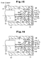
- a seventh embodiment according to the present invention will now be described with reference to Figs. 15 and 16.
- the rotated guide 57 is similar to that of the first embodiment.
- a fixed guide is defined on the valve plate 14 in the same manner as the fifth embodiment.
- An accommodating chamber 68 which is similar to the valve chamber 52 of the second embodiment, is located in the bleeding passage 47 between the displacement control valve 61 and the suction chamber 38.
- a valve port 69 which is coaxial to the shaft axis L, extends through the valve plate 14. The suction chamber 38 and the accommodation chamber 68 are connected to each other through the valve port 69.
- the valve body 67 includes a main portion 67a, which is arranged in the suction chamber 38, a contact portion 67b, which is arranged in the accommodating chamber 68, and a rod 67c, which extends through the valve port 69 and integrally connects the main portion 67a to the contact portion 67b.
- the main portion 67a is spherical.
- the contact portion 67b has a conical surface 67d, the diameter of which decreases at locations closer to the drive shaft 16.
- a coil spring 70 is arranged in the suction chamber 38 to urge the main portion 67a in a direction closing the valve port 69. Contact between the conical surface 67d and the orbiting balls 59 restricts movement of the contact portion 67 toward the drive shaft 16.
- the main portion 67a keeps the valve port 69 opened under normal conditions, as shown in Fig. 15.
- the centrifugal force applied to the balls 59 weakens. Accordingly, the force of the spring 60 moves the rotated guide 57 toward the valve plate 14 such that the guide surface 57a approaches the guide surface 14b. This decreases the orbiting radius of the balls 59. The decreased orbiting radius moves the contact portion 67b toward the valve plate 14. This moves the main portion 67a against the force of the spring 70 and opens the valve port 69.
- a central bore 26 extends through the center of the cylinder block 12 to receive the drive shaft 16.
- An accommodating chamber 51 is defined at the rear portion of the central bore 26.
- a cylindrical radial bearing 27 is arranged in the central bore 26 to support the rear end of the drive shaft 16.
- the crank chamber 15 and the suction chamber 38 are connected to each other by the bleeding passage 47.
- the bleeding passage 47 includes a communication conduit 16c, which extends through the drive shaft 16 along the axis L, the accommodating chamber 51, and a pressure releasing hole 14b, which extends through the center of the valve plate 14.
- the front end of the communication passage 16c is connected with the crank chamber 15 near the radial bearing 20.
- an end bearing 71 and a shaft spring 72 are arranged between the rear end of the drive shaft 16 and the valve plate 14.
- the bleeding passage 47 is closed by the valve V, which is formed in the accommodating chamber 51.
- a valve hole 73 which is connected to the communication conduit 16c, extends through the rear portion of the drive shaft 16. The rear portion of the communication conduit 16c is sealed by a plug 74.
- a valve body 75 is movably inserted into the valve hole 73.
- a spring 76 urges the valve body 75 in a direction opening the valve hole 73.
- a counterweight 77 is attached to the valve body 75 on the other side of the drive shaft 16.
- Nc the centrifugal force applied to the counterweight 77 moves the counterweight 77 radially. This moves the valve body 75 against the force of the spring 76 and closes the valve hole 73. In this state, the flow of refrigerant gas in the bleeding passage 47 from the crank chamber 15 to the suction chamber 38 is stopped.
- the force of the spring 76 keeps the bleeding passage 47 opened by the valve body 75 as long as the rotating speed N of the drive shaft 16 remains lower than the limit value Nc. Accordingly, the valve V opens and closes the bleeding passage 47 in accordance with the rotating speed N of the drive shaft 16 with a simple structure.
- the swash plate 21 has a hinge portion 25, which is an off-center mass.
- the counterweight 77 is located on the opposite side of the drive shaft 16 from the hinge portion 25. In other words, the angular interval, as measured about the drive shaft 16, between the counterweight 77 and the hinge portion 25 is 180°. Therefore, the counterweight 77 balances the weight of the hinge portion 25 and causes the drive shaft 16 to rotate without vibrations.
- the accommodating chamber 51 which is included in the central bore 26, is located behind the axis L of the drive shaft 16. Furthermore, the central bore 26 is used to receive the rear end of the drive shaft 16 and the radial bearing 27, which is an ordinary cylindrical bearing that is arranged between the wall of the central bore 26 and the drive shaft 16. Therefore, the radial dimension of the cylinder block 12 may be decreased in comparison to when using roller bearings, such as needle bearings.
- the gap between the drive shaft 16 and the wall of the central bore 26 can be narrowed. This decreases the amount of the refrigerant gas in the crank chamber 15 that is sent to the accommodating chamber 51 and the suction chamber 38 through the gap.
- the valve V when the valve V is closed, the pressure of the crank chamber 15 is increased at a gradual rate. In other words, a sudden increase in the pressure of the crank chamber 15 is prevented.
- the minimum displacement may be set within a range of 30% to 60% of the maximum displacement.
- a rod arranged between the rotor 19 and the swash plate 21 may be employed in lieu of the snap ring 23 to restrict the inclination of the swash plate 21.
- the inclination of the swash plate 21 corresponding to the minimum displacement state is adjusted during assembly of the compressor.
- the opposing guide surfaces 53a, 57a, 14b (16b, 62a in the second embodiment) may both be conical surfaces.
- the rotated guide surface 16b (57a in the fifth embodiment) is conical.
- the fixed guide surface 62a (14b) of the valve body 62 may be conical instead such that its diameter increases at positions closer to the rotated guide surface 16a (57a).
- the number of orbiting balls 59 may be more than or less than five.
- the guides and the orbiting balls function as thrust ball bearings.
- the balls may be replaced by other types of orbiting elements, such as cylindrical needles or rollers that function as a roller-type bearing.
- a displacement control valve may be arranged in the bleeding passage 47 to adjust the opened size of the bleeding passage 47 and change the pressure of the crank chamber 15.
- the displacement control valve may be arranged in the supply passage 48 to adjust the opened size of the supply passage 48 and changed the pressure of the crank chamber 15.
- the supply passage 48 and the displacement control valve 49 may be eliminated.
- the compressor is operated in a maximum displacement state under normal conditions, and the valve V shifts the displacement from maximum to minimum during acceleration of the vehicle.
- a variable displacement compressor having a pressurizing passage (55), which extends through a cylinder block (12).
- the pressurizing passage (55) connects a discharge chamber (39) and a crank chamber (15).
- a valve (V) is arranged in the pressurizing passage (55).
- a drive shaft (16) rotates and produces centrifugal force that causes the valve (V) to open the pressurizing passage (55).
- the pressure of the crank chamber (15) is increased when the rotation of the drive shaft (16) is accelerated thereby opening the pressurizing passage (55) with the valve (V). This moves a swash plate (21) such that its inclination, relative to a plane perpendicular to the drive shaft (16), decreases.
- the compressor shifts from a maximum displacement state to a minimum displacement state, which improves the acceleration performance of an engine connected to the compressor. Furthermore, the displacement of the compressor in the minimum displacement state is 50% of that in the maximum displacement state. This prevents an excessive decrease in the cooling capability of the compressor.
Landscapes
- Engineering & Computer Science (AREA)
- Mechanical Engineering (AREA)
- General Engineering & Computer Science (AREA)
- Compressors, Vaccum Pumps And Other Relevant Systems (AREA)
- Control Of Positive-Displacement Pumps (AREA)
- Compressor (AREA)
Applications Claiming Priority (2)
| Application Number | Priority Date | Filing Date | Title |
|---|---|---|---|
| JP9006098 | 1998-04-02 | ||
| JP9006098A JPH11287181A (ja) | 1998-04-02 | 1998-04-02 | 可変容量圧縮機 |
Publications (2)
| Publication Number | Publication Date |
|---|---|
| EP0947694A2 true EP0947694A2 (fr) | 1999-10-06 |
| EP0947694A3 EP0947694A3 (fr) | 2000-02-23 |
Family
ID=13988033
Family Applications (1)
| Application Number | Title | Priority Date | Filing Date |
|---|---|---|---|
| EP99106498A Withdrawn EP0947694A3 (fr) | 1998-04-02 | 1999-03-30 | Soupape de contrôle pour un compresseur en plateau en biais à capacité variable |
Country Status (3)
| Country | Link |
|---|---|
| US (1) | US6164926A (fr) |
| EP (1) | EP0947694A3 (fr) |
| JP (1) | JPH11287181A (fr) |
Cited By (1)
| Publication number | Priority date | Publication date | Assignee | Title |
|---|---|---|---|---|
| EP2096308A3 (fr) * | 2008-02-28 | 2010-05-12 | Kabushiki Kaisha Toyota Jidoshokki | Compresseur à déplacement variable de type brise-flot |
Families Citing this family (10)
| Publication number | Priority date | Publication date | Assignee | Title |
|---|---|---|---|---|
| JP2000145629A (ja) * | 1998-11-11 | 2000-05-26 | Tgk Co Ltd | 容量可変圧縮機 |
| JP2000320454A (ja) * | 1999-05-13 | 2000-11-21 | Toyota Autom Loom Works Ltd | 可変容量圧縮機 |
| US6390782B1 (en) * | 2000-03-21 | 2002-05-21 | Alumina Micro Llc | Control valve for a variable displacement compressor |
| JP4078229B2 (ja) * | 2002-03-20 | 2008-04-23 | カルソニックカンセイ株式会社 | 圧縮機 |
| JP2008038856A (ja) * | 2006-08-10 | 2008-02-21 | Toyota Industries Corp | 可変容量型圧縮機用制御弁 |
| JP4924464B2 (ja) * | 2008-02-05 | 2012-04-25 | 株式会社豊田自動織機 | 斜板式圧縮機 |
| JP2009209910A (ja) * | 2008-03-06 | 2009-09-17 | Toyota Industries Corp | 斜板式圧縮機 |
| US9163620B2 (en) | 2011-02-04 | 2015-10-20 | Halla Visteon Climate Control Corporation | Oil management system for a compressor |
| JP7048177B2 (ja) * | 2018-06-27 | 2022-04-05 | サンデン・オートモーティブコンポーネント株式会社 | 可変容量圧縮機 |
| CN115324888B (zh) * | 2021-05-10 | 2024-06-11 | 北京汽车动力总成有限公司 | 一种机油泵及汽车 |
Citations (1)
| Publication number | Priority date | Publication date | Assignee | Title |
|---|---|---|---|---|
| US4872814A (en) | 1988-06-09 | 1989-10-10 | General Motors Corporation | Variable displacement compressor passive destroker |
Family Cites Families (12)
| Publication number | Priority date | Publication date | Assignee | Title |
|---|---|---|---|---|
| US2657699A (en) * | 1949-01-29 | 1953-11-03 | Curtiss Wright Corp | Fluid pressure speed sensing device |
| JPS5924821Y2 (ja) * | 1978-07-31 | 1984-07-23 | ヤマハ発動機株式会社 | 2サイクルエンジンにおけるロ_タリ式排気バルブの駆動装置 |
| JPS61134580A (ja) * | 1984-12-03 | 1986-06-21 | 石川島播磨重工業株式会社 | 溶解炉 |
| JPS61134580U (fr) * | 1985-02-09 | 1986-08-22 | ||
| US4606705A (en) * | 1985-08-02 | 1986-08-19 | General Motors Corporation | Variable displacement compressor control valve arrangement |
| JPH085310B2 (ja) * | 1989-04-29 | 1996-01-24 | 日産自動車株式会社 | 車両用空調装置 |
| US5071321A (en) * | 1989-10-02 | 1991-12-10 | General Motors Corporation | Variable displacement refrigerant compressor passive destroker |
| JPH04339189A (ja) * | 1991-05-15 | 1992-11-26 | Sanden Corp | スクロール型流体装置 |
| US5417552A (en) * | 1992-10-20 | 1995-05-23 | Kabushiki Kaisha Toyoda Jidoshokki Seisakusho | Swash plate type variable displacement compressor |
| JPH08326655A (ja) * | 1995-06-05 | 1996-12-10 | Calsonic Corp | 斜板式コンプレッサ |
| JP3282457B2 (ja) * | 1995-08-21 | 2002-05-13 | 株式会社豊田自動織機 | 片頭ピストン型圧縮機 |
| KR100215157B1 (ko) * | 1996-06-19 | 1999-08-16 | 이소가이 지세이 | 가변용량 압축기 및 그 부착방법 |
-
1998
- 1998-04-02 JP JP9006098A patent/JPH11287181A/ja active Pending
-
1999
- 1999-03-26 US US09/277,697 patent/US6164926A/en not_active Expired - Fee Related
- 1999-03-30 EP EP99106498A patent/EP0947694A3/fr not_active Withdrawn
Patent Citations (1)
| Publication number | Priority date | Publication date | Assignee | Title |
|---|---|---|---|---|
| US4872814A (en) | 1988-06-09 | 1989-10-10 | General Motors Corporation | Variable displacement compressor passive destroker |
Cited By (1)
| Publication number | Priority date | Publication date | Assignee | Title |
|---|---|---|---|---|
| EP2096308A3 (fr) * | 2008-02-28 | 2010-05-12 | Kabushiki Kaisha Toyota Jidoshokki | Compresseur à déplacement variable de type brise-flot |
Also Published As
| Publication number | Publication date |
|---|---|
| EP0947694A3 (fr) | 2000-02-23 |
| US6164926A (en) | 2000-12-26 |
| JPH11287181A (ja) | 1999-10-19 |
Similar Documents
| Publication | Publication Date | Title |
|---|---|---|
| EP0748937B1 (fr) | Dispositif de commande de déplacement pour un compresseur à déplacement variable sans embrayage | |
| US6361283B1 (en) | Displacement control valve | |
| EP0550201B1 (fr) | Compresseur à plateau en biais avec dispositif à déplacement variable | |
| US6358017B1 (en) | Control valve for variable displacement compressor | |
| US6457319B1 (en) | Air conditioner and control valve in variable displacement compressor | |
| US5332365A (en) | Slant plate type compressor with variable capacity control mechanism | |
| US6354811B1 (en) | Control valve for variable displacement compressors | |
| EP0848164B1 (fr) | Soupape de contrôle pour compresseur à capacité variable | |
| US5165863A (en) | Slant plate type compressor with variable capacity control mechanism | |
| US6062824A (en) | Control valve | |
| US6234763B1 (en) | Variable displacement compressor | |
| US6398516B1 (en) | Variable displacement compressors and control valves for variable displacement compressors | |
| JPH0637874B2 (ja) | 可変容量圧縮機 | |
| EP0536989A1 (fr) | Compresseur à plateau en biais avec dispositif à déplacement variable | |
| US5586870A (en) | Bearing structure used in a compressor | |
| US6290468B1 (en) | Variable displacement compressor | |
| US20090223244A1 (en) | Swash plate type compressor | |
| US5603610A (en) | Clutchless piston type variable displacement compressor | |
| EP2096308B1 (fr) | Compresseur à déplacement variable de type brise-flot | |
| US6164926A (en) | Variable displacement compressor | |
| EP0947695B1 (fr) | Soupape de contrôle pour un compresseur en plateau en biais à capacité variable | |
| EP1024286A2 (fr) | Soupape de contrôle pour un compresseur à plateau en biais à capacité variable | |
| US6076449A (en) | Variable displacement compressor | |
| US6544004B2 (en) | Single-headed piston type compressor | |
| US5713725A (en) | Clutchless piston type variable displacement compressor |
Legal Events
| Date | Code | Title | Description |
|---|---|---|---|
| PUAI | Public reference made under article 153(3) epc to a published international application that has entered the european phase |
Free format text: ORIGINAL CODE: 0009012 |
|
| 17P | Request for examination filed |
Effective date: 19990330 |
|
| AK | Designated contracting states |
Kind code of ref document: A2 Designated state(s): DE FR IT |
|
| AX | Request for extension of the european patent |
Free format text: AL;LT;LV;MK;RO;SI |
|
| PUAL | Search report despatched |
Free format text: ORIGINAL CODE: 0009013 |
|
| AK | Designated contracting states |
Kind code of ref document: A3 Designated state(s): AT BE CH CY DE DK ES FI FR GB GR IE IT LI LU MC NL PT SE |
|
| AX | Request for extension of the european patent |
Free format text: AL;LT;LV;MK;RO;SI |
|
| AKX | Designation fees paid |
Free format text: DE FR IT |
|
| STAA | Information on the status of an ep patent application or granted ep patent |
Free format text: STATUS: THE APPLICATION IS DEEMED TO BE WITHDRAWN |
|
| 18D | Application deemed to be withdrawn |
Effective date: 20021001 |