EP0947855B1 - Vorrichtung und Verfahren zur simultanen Messung von unterschiedlichen Strahlungsarten - Google Patents
Vorrichtung und Verfahren zur simultanen Messung von unterschiedlichen Strahlungsarten Download PDFInfo
- Publication number
- EP0947855B1 EP0947855B1 EP99101584A EP99101584A EP0947855B1 EP 0947855 B1 EP0947855 B1 EP 0947855B1 EP 99101584 A EP99101584 A EP 99101584A EP 99101584 A EP99101584 A EP 99101584A EP 0947855 B1 EP0947855 B1 EP 0947855B1
- Authority
- EP
- European Patent Office
- Prior art keywords
- scintillator
- radiation
- scintillators
- type
- discriminative
- Prior art date
- Legal status (The legal status is an assumption and is not a legal conclusion. Google has not performed a legal analysis and makes no representation as to the accuracy of the status listed.)
- Expired - Lifetime
Links
- 230000005855 radiation Effects 0.000 title claims description 117
- 238000000034 method Methods 0.000 title claims description 35
- 238000005259 measurement Methods 0.000 title claims description 11
- 230000005251 gamma ray Effects 0.000 claims description 48
- 239000000463 material Substances 0.000 claims description 37
- 230000035945 sensitivity Effects 0.000 claims description 30
- 229910052688 Gadolinium Inorganic materials 0.000 claims description 16
- UIWYJDYFSGRHKR-UHFFFAOYSA-N gadolinium atom Chemical compound [Gd] UIWYJDYFSGRHKR-UHFFFAOYSA-N 0.000 claims description 16
- 230000005250 beta ray Effects 0.000 claims description 13
- 229910052693 Europium Inorganic materials 0.000 claims description 11
- 239000000126 substance Substances 0.000 claims description 10
- 239000013307 optical fiber Substances 0.000 claims description 8
- 229910052771 Terbium Inorganic materials 0.000 claims description 7
- 229910052984 zinc sulfide Inorganic materials 0.000 claims description 7
- 239000003086 colorant Substances 0.000 claims description 6
- OGPBJKLSAFTDLK-UHFFFAOYSA-N europium atom Chemical compound [Eu] OGPBJKLSAFTDLK-UHFFFAOYSA-N 0.000 claims description 6
- 230000035515 penetration Effects 0.000 claims description 5
- UFHFLCQGNIYNRP-UHFFFAOYSA-N Hydrogen Chemical compound [H][H] UFHFLCQGNIYNRP-UHFFFAOYSA-N 0.000 claims description 4
- 229910052739 hydrogen Inorganic materials 0.000 claims description 4
- 239000001257 hydrogen Substances 0.000 claims description 4
- 229910052709 silver Inorganic materials 0.000 claims description 4
- 239000004332 silver Substances 0.000 claims description 4
- GZCRRIHWUXGPOV-UHFFFAOYSA-N terbium atom Chemical compound [Tb] GZCRRIHWUXGPOV-UHFFFAOYSA-N 0.000 claims description 4
- VYZAMTAEIAYCRO-UHFFFAOYSA-N Chromium Chemical compound [Cr] VYZAMTAEIAYCRO-UHFFFAOYSA-N 0.000 claims description 3
- 229910052777 Praseodymium Inorganic materials 0.000 claims description 3
- 239000011521 glass Substances 0.000 claims description 2
- PUDIUYLPXJFUGB-UHFFFAOYSA-N praseodymium atom Chemical compound [Pr] PUDIUYLPXJFUGB-UHFFFAOYSA-N 0.000 claims description 2
- -1 cerium-activated yttrium aluminate Chemical class 0.000 claims 12
- 150000000921 Gadolinium Chemical class 0.000 claims 5
- 229910052684 Cerium Inorganic materials 0.000 claims 4
- LNTHITQWFMADLM-UHFFFAOYSA-N gallic acid Chemical compound OC(=O)C1=CC(O)=C(O)C(O)=C1 LNTHITQWFMADLM-UHFFFAOYSA-N 0.000 claims 3
- PBYZMCDFOULPGH-UHFFFAOYSA-N tungstate Chemical compound [O-][W]([O-])(=O)=O PBYZMCDFOULPGH-UHFFFAOYSA-N 0.000 claims 3
- 108010043121 Green Fluorescent Proteins Proteins 0.000 claims 2
- BPQQTUXANYXVAA-UHFFFAOYSA-N Orthosilicate Chemical compound [O-][Si]([O-])([O-])[O-] BPQQTUXANYXVAA-UHFFFAOYSA-N 0.000 claims 2
- GWXLDORMOJMVQZ-UHFFFAOYSA-N cerium Chemical compound [Ce] GWXLDORMOJMVQZ-UHFFFAOYSA-N 0.000 claims 2
- CMIHHWBVHJVIGI-UHFFFAOYSA-N gadolinium(III) oxide Inorganic materials [O-2].[O-2].[O-2].[Gd+3].[Gd+3] CMIHHWBVHJVIGI-UHFFFAOYSA-N 0.000 claims 2
- 239000010955 niobium Substances 0.000 claims 2
- 229910004829 CaWO4 Inorganic materials 0.000 claims 1
- OYPRJOBELJOOCE-UHFFFAOYSA-N Calcium Chemical compound [Ca] OYPRJOBELJOOCE-UHFFFAOYSA-N 0.000 claims 1
- 229910017672 MgWO4 Inorganic materials 0.000 claims 1
- HCHKCACWOHOZIP-UHFFFAOYSA-N Zinc Chemical compound [Zn] HCHKCACWOHOZIP-UHFFFAOYSA-N 0.000 claims 1
- 229910052793 cadmium Inorganic materials 0.000 claims 1
- BDOSMKKIYDKNTQ-UHFFFAOYSA-N cadmium atom Chemical compound [Cd] BDOSMKKIYDKNTQ-UHFFFAOYSA-N 0.000 claims 1
- 229910052791 calcium Inorganic materials 0.000 claims 1
- 239000011575 calcium Substances 0.000 claims 1
- 229910052804 chromium Inorganic materials 0.000 claims 1
- DJZHPOJZOWHJPP-UHFFFAOYSA-N magnesium;dioxido(dioxo)tungsten Chemical compound [Mg+2].[O-][W]([O-])(=O)=O DJZHPOJZOWHJPP-UHFFFAOYSA-N 0.000 claims 1
- 229910052758 niobium Inorganic materials 0.000 claims 1
- LSGOVYNHVSXFFJ-UHFFFAOYSA-N vanadate(3-) Chemical compound [O-][V]([O-])([O-])=O LSGOVYNHVSXFFJ-UHFFFAOYSA-N 0.000 claims 1
- 150000003746 yttrium Chemical class 0.000 claims 1
- 229910052725 zinc Inorganic materials 0.000 claims 1
- 239000011701 zinc Substances 0.000 claims 1
- 238000002601 radiography Methods 0.000 description 19
- 230000002285 radioactive effect Effects 0.000 description 13
- ZOXJGFHDIHLPTG-UHFFFAOYSA-N Boron Chemical compound [B] ZOXJGFHDIHLPTG-UHFFFAOYSA-N 0.000 description 9
- WHXSMMKQMYFTQS-UHFFFAOYSA-N Lithium Chemical compound [Li] WHXSMMKQMYFTQS-UHFFFAOYSA-N 0.000 description 8
- 230000005260 alpha ray Effects 0.000 description 8
- 229910052796 boron Inorganic materials 0.000 description 8
- 238000003384 imaging method Methods 0.000 description 8
- 238000006243 chemical reaction Methods 0.000 description 7
- 230000008569 process Effects 0.000 description 7
- 239000005083 Zinc sulfide Substances 0.000 description 6
- 229910052744 lithium Inorganic materials 0.000 description 6
- 238000010521 absorption reaction Methods 0.000 description 5
- 230000008901 benefit Effects 0.000 description 5
- 238000010586 diagram Methods 0.000 description 4
- 239000000835 fiber Substances 0.000 description 4
- 238000007689 inspection Methods 0.000 description 4
- 238000012986 modification Methods 0.000 description 4
- 230000004048 modification Effects 0.000 description 4
- 230000003287 optical effect Effects 0.000 description 4
- BQCADISMDOOEFD-UHFFFAOYSA-N Silver Chemical compound [Ag] BQCADISMDOOEFD-UHFFFAOYSA-N 0.000 description 3
- 238000012937 correction Methods 0.000 description 3
- 230000000694 effects Effects 0.000 description 3
- DRDVZXDWVBGGMH-UHFFFAOYSA-N zinc;sulfide Chemical compound [S-2].[Zn+2] DRDVZXDWVBGGMH-UHFFFAOYSA-N 0.000 description 3
- OKTJSMMVPCPJKN-UHFFFAOYSA-N Carbon Chemical compound [C] OKTJSMMVPCPJKN-UHFFFAOYSA-N 0.000 description 2
- 229910052799 carbon Inorganic materials 0.000 description 2
- 238000012850 discrimination method Methods 0.000 description 2
- 238000010894 electron beam technology Methods 0.000 description 2
- MIKCAECBBIRHCH-UHFFFAOYSA-N gadolinium(3+);oxygen(2-);trisulfide Chemical compound [O-2].[O-2].[O-2].[S-2].[S-2].[S-2].[Gd+3].[Gd+3].[Gd+3].[Gd+3] MIKCAECBBIRHCH-UHFFFAOYSA-N 0.000 description 2
- 230000001788 irregular Effects 0.000 description 2
- 239000011347 resin Substances 0.000 description 2
- 229920005989 resin Polymers 0.000 description 2
- 229910052686 Californium Inorganic materials 0.000 description 1
- 230000003213 activating effect Effects 0.000 description 1
- HGLDOAKPQXAFKI-UHFFFAOYSA-N californium atom Chemical compound [Cf] HGLDOAKPQXAFKI-UHFFFAOYSA-N 0.000 description 1
- 230000008859 change Effects 0.000 description 1
- 238000007796 conventional method Methods 0.000 description 1
- 230000007547 defect Effects 0.000 description 1
- 230000001419 dependent effect Effects 0.000 description 1
- 230000006866 deterioration Effects 0.000 description 1
- 238000011161 development Methods 0.000 description 1
- 230000018109 developmental process Effects 0.000 description 1
- 239000000839 emulsion Substances 0.000 description 1
- 229910001385 heavy metal Inorganic materials 0.000 description 1
- 230000005865 ionizing radiation Effects 0.000 description 1
- 229910052751 metal Inorganic materials 0.000 description 1
- 239000002184 metal Substances 0.000 description 1
- 239000007769 metal material Substances 0.000 description 1
- 239000004238 monoammonium glutamate Substances 0.000 description 1
- 230000002093 peripheral effect Effects 0.000 description 1
- 230000035699 permeability Effects 0.000 description 1
- 239000000088 plastic resin Substances 0.000 description 1
- 230000001915 proofreading effect Effects 0.000 description 1
- 239000000941 radioactive substance Substances 0.000 description 1
- 238000002310 reflectometry Methods 0.000 description 1
- 238000011160 research Methods 0.000 description 1
- 239000004065 semiconductor Substances 0.000 description 1
- 230000000638 stimulation Effects 0.000 description 1
- 238000012360 testing method Methods 0.000 description 1
Images
Classifications
-
- G—PHYSICS
- G01—MEASURING; TESTING
- G01T—MEASUREMENT OF NUCLEAR OR X-RADIATION
- G01T7/00—Details of radiation-measuring instruments
-
- G—PHYSICS
- G01—MEASURING; TESTING
- G01T—MEASUREMENT OF NUCLEAR OR X-RADIATION
- G01T1/00—Measuring X-radiation, gamma radiation, corpuscular radiation, or cosmic radiation
- G01T1/16—Measuring radiation intensity
- G01T1/20—Measuring radiation intensity with scintillation detectors
- G01T1/2008—Measuring radiation intensity with scintillation detectors using a combination of different types of scintillation detectors, e.g. phoswich
Definitions
- the present invention relates to a radiation discriminative measuring apparatus and a radiation discriminative measuring method for use in industries and research facilities, such as a nuclear industry, a radiology and facilities using radioactivity and capable of discriminating and measuring a radiation from radiations (radioactive rays) in which ⁇ ray, ⁇ ray, X ray, ⁇ ray and neutron ray are mixed and enabling a nondestructive test to be performed.
- industries and research facilities such as a nuclear industry, a radiology and facilities using radioactivity and capable of discriminating and measuring a radiation from radiations (radioactive rays) in which ⁇ ray, ⁇ ray, X ray, ⁇ ray and neutron ray are mixed and enabling a nondestructive test to be performed.
- a method using the X ray or the ⁇ ray among various radiations has been known as the radiography.
- the X ray or the ⁇ ray is able to easily penetrate an object.
- these rays are able to easily penetrate the object if the object has a light weight. Therefore, these rays are widely used to detect the internal state of an object.
- the X ray or the ⁇ ray easily penetrates an object if the object has light weight. Therefore, the foregoing rays easily penetrate light elements having small atomic numbers.
- a substance containing hydrogen or the like concealed in a metal material cannot easily be inspected.
- the X ray or the ⁇ ray cannot easily discriminate a small difference, for example, the difference between boron and carbon which are elements having adjacent atomic numbers.
- radiograph using neutrons has been used.
- the radiography of the foregoing type is able to discriminate light elements which are contained in a metal object and which cannot be discriminated by the X ray or the ⁇ ray because absorption of neutrons does not depend on the atomic number and neutrons penetrate heavy substances.
- Each element has inherent absorption and scattering cross sectional area with respect to the neutrons such that neutrons are absorbed by boron in a large quantity.
- neutrons are not considerably absorbed by carbon. Therefore, nondestructive inspection using neutrons to discriminate light elements has been employed.
- radiography using the advantages of both of the radiography using X ray or ⁇ ray and the radiography using neutrons has been employed.
- pyrotechnic product has been nondestructively inspected.
- the radiography using, the X ray or ⁇ ray and neutrons must perform two times of processes for inspecting one sample by using the X ray or ⁇ ray and neutrons. Therefore, a long measuring time is required and a complicated operation must be performed.
- a simultaneous radiography method has been disclosed in, for example, Japanese Patent Laid-Open Publication No. SHO 58-113842, in which californium 252 Cf is employed as a neutron source and a ⁇ ray source. Moreover, a ⁇ ray image detector and a neutron image detector are disposed adjacently so as to simultaneously record images on films set to the detectors.
- the above-mentioned method requires two films for recording images. Therefore, accurate position alignment cannot be performed and a complicated image process must be performed.
- a method structured by modifying the above-mentioned simultaneous radiography method has been disclosed in, for example, Japanese Patent Laid-Open Publication No. SHO 61-184444, in which a ⁇ ray image and a neutron image are measured in accordance with the color.
- the simultaneous radiography disclosed in Japanese Patent Laid-Open Publication No. SHO 61-184444 employs combination of a red-light emitting scintillator for a ⁇ ray image and a blue- or green-light emitting scintillator for neutrons.
- a ⁇ ray image and a neutron image are measured in accordance with the color.
- the scintillator for the ⁇ ray image has a structure that a fluorescent material emitting red light is applied or evaporated on the surface of a heavy-metal plate.
- the scintillator for neutrons has a structure that a fluorescent material for emitting blue or green light is mixed or applied to a substance containing lithium (Li-6) or boron (B-10). Neutrons and lithium or boron cause (n, ⁇ ) reaction, causing alpha ( ⁇ ) rays to be generated which develops the blue-light fluorescent material to develop blue color.
- the blue-light emitting fluorescent member contains a fluorescent material which is zinc sulfide (ZnS:Ag) is employed which is activated with silver.
- the method uses one film on which a neutron radiography is recorded in blue, and X ray or ⁇ ray radiography is recorded in red to discriminate the image in accordance with the color.
- a neutron radiography is recorded in blue
- X ray or ⁇ ray radiography is recorded in red to discriminate the image in accordance with the color.
- the above-mentioned method is able to correct fog caused from the X ray and the ⁇ ray.
- the foregoing method using the fluorescent member in the form of combined with zinc sulfide (ZnS:Ag) activated with silver has an advantage that the amount of fogging with respect to the X ray or the ⁇ ray can be reduced.
- realized sensitivity has been unsatisfactory.
- the employed scintillator is not formed of a material through which the ⁇ ray and the neutrons are able to penetrate. Therefore, it was required to employ a structure in which scintillators are disposed in such a manner that a film is interposed between a scintillator for a ⁇ ray image and a scintillator for neutrons. Therefore, it was difficult as a usable technique to perform light emission of three or more colors by disposing three scintillators.
- An imaging plate for neutrons has been developed as disclosed in, for example, Japanese Patent Laid-Open Publication No. HEI 4-290985.
- the disclosed method has improved sensitivity to neutrons.
- This method utilizes a stimulation light emission of the fluorescent material which is a phenomenon causing light to be emitted by means of stimulus, such as heat or light, after irradiation with electron rays or radiations.
- the imaging plate has a structure formed by applying a stimulus fluorescent material. Specifically, the imaging plate uses gadolinium (Gd) in the reactions with neutrons.
- activating material is a sintered material containing praseodymium (Pr), terbium (Tb) or europium (Eu).
- the above-mentioned imaging plate has been improved into a developed structure formed by combining an imaging plate for the X ray and an imaging plate for neutrons which is made of lithium (Li-6), boron (B-10) or gadolinium (Gd).
- the imaging plate for neutrons has a structure incorporating the stimulus fluorescent material and arranged to capture and store a signal caused from ionizing radiation as a color center. Moreover, a light beam emitted from a reading unit causes fluorescent light to be emitted so as to form an image. Therefore, the described method has advantages that a high sensitivity to neutrons can be realized and an operation in a bright region is permitted. However, there arises a problem in terms of performing a real-time operation because an individual reading operation must be performed after neutrons have been applied. Since the above-mentioned technique has been developed to be adaptable to X ray, high sensitivity to the X ray and that to they ⁇ ray can be realized.
- Patent Abstracts of Japan, vol. 19, no. 217 (E-624), 21.06.1998; Pub. No. JP-A-63012179 describes a radiation detector for simultaneously detecting the respective radiation dose rates using the radiation qualities of all radioactive rays, i.e. ⁇ -, ⁇ - and y-rays.
- the radiation detector comprises electrodes of a semiconductor element for radioactive rays, which make ⁇ -, ⁇ - and ⁇ -rays penetrate in accordance with their penetration force in a manner, such that ⁇ -rays only, ⁇ -rays and ⁇ -ray only and ⁇ -, ⁇ - and ⁇ -rays penetrate through the electrodes.
- Patent Abstracts of Japan, vol. 98, no. 1, 30.01.1998; Pub. No. JP-A-9236669 describes a fiber type radiation detector, wherein a radiation-sensitive layer containing a thin stratified radiation-sensitive substance including a scintillator is formed on the outer peripheral surface of a clad of a fluorescent optical fiber of a small diameter.
- US 5,317,158 discloses a radiation discriminative measuring apparatus, comprising a plurality of scintillators (alpha scintillator, beta scintillator and gamma scintillator), each emitting a characteristic waveshape, which are detected by a photomultiplier.
- the different waveshapes are electronically separated on the basis of their duration.
- An object of the present invention is to substantially eliminate defects or drawbacks encountered in the prior art described above and to provide a radiation discriminative measuring apparatus which is capable of discriminating radiations (radioactive rays) consisting of, for example, a rays, ⁇ rays, ⁇ rays, neutron rays and X ray and forming the discriminated radiations into images without any time lag by directly photographing (imaging) the radioactive rays.
- radiations radioactive rays
- Another object of the present invention is to provide a radiation discriminative measuring method with which a sensitive image can be formed by correcting fogging of a picked image by improving the material and thickness of scintillators.
- the structure of one aspect of the present invention enables a radiation discriminative measurement to be performed.
- the image pickup means for recording signals emitted in accordance with the wavelength is a color film so that the signals are recorded on one film.
- the conventional film method for using a film has employed the industrial X ray film because of its sensitivity and the resolution of the image quality.
- the wavelength components cannot individually be read from the film on which the signals have been recorded.
- the industrial X ray film has surfaces coated with emulsion which are provided for one side and both sides with respect to the base film. Therefore, even if such film is set inversely with respect to the scintillator, recording is permitted.
- the structure is provided with a dichroic mirror having optimum permeability and reflectivity adaptable to the wavelength of light beams emitted from the scintillators. As a result, wavelengths can efficiently be identified and observed.
- a three-plate type CCD camera or a three-tube type camera may be provided.
- the optical fiber may be disposed between the scintillator, which is emitting light, and a recording medium, such as a film, or a camera or photomultiplier so as to transmit a light signal. Therefore, the distance from the photodetector can be elongated.
- a tapered fiber is directly disposed in close contact to a light receiving device of the camera, an optical image forming device, such as a lens, may be omitted.
- the image intensifier and a microchannel plate may be disposed between the scintillator and the photodetector.
- the image intensifier and a microchannel plate may be disposed between the scintillator and the photodetector.
- the sensitivity can be raised.
- a structure of combination with the optical fiber is employed, a loss occurring in transmitting a signal can be prevented.
- the microchannel plate or the like is employed to amplify the light signal, a structure incorporating a red-light emitting member as the fluorescent member disposed to the amplifying portion improves a wavelength sensitivity characteristic (having a sensitivity peak at about 700 nm) of the CCD camera, and the matching to the CCD camera can be improved. As a result, the sensitivity can further be improved.
- the color film is accommodated in the image pickup cassette which is able to shield scintillators emitting multiple colors so that an integrated structure is formed. Furthermore, since the film is made to be detachable, the films for the neutrons which have been individually provided can be integrated into one film. Therefore, the necessity of performing individual developing processes can be eliminated.
- the first and second scintillators are red-light emitting or green-light emitting scintillators for thermal neutrons.
- a resin containing hydrogen is interposed between the first scintillator and the second scintillator.
- the thickness of the scintillator is determined to cause the first scintillator to substantially completely absorb the thermal neutrons.
- the scintillator mainly composed of gadolinium (Gd) which serves as the member for absorbing thermal neutrons is required to have a thickness of tens of mm.
- the fast neutrons are not absorbed by the first scintillator and allowed to pass through the same. Therefore, the resin containing hydrogen is used to decelerate the fast neutrons so as to convert the same into thermal neutrons.
- the second scintillator for thermal neutrons is caused to emit light.
- the scintillators for emitting light beams having individual wavelengths are adapted to the types A, B and C of the radiations.
- the first scintillator is designed to have high sensitivity with respect to radiation A. Since the first scintillator has sensitivity to B type and C type radiation in the strict sense, a result covered with the B and C type radiations is obtained. Therefore, the first scintillator has a thickness with which the radiation A can completely be shielded. If the type A of the radiation is ⁇ ray, the scintillator must have a thickness of several mm. If the type A is the ⁇ ray, the ⁇ ray can be shielded if the thickness is tens of mm or greater.
- the second scintillator is designed to have high sensitivity to types B and C of radiations rays which pass through the first scintillator, in particular to the type B radiation. If the type B of the radiation ray is ⁇ ray or neutron ray to be described later, the scintillator is required to have a small thickness of tens of mm. If the thickness of such scintillator is enlarged, the sensitivity to the X ray and that to the ⁇ ray are raised excessively.
- the third scintillator is designed to have high sensitivity to type C radiation which cannot be shielded by the second scintillator and which thus penetrates the second scintillator.
- the third scintillator has a small thickness and high sensitivity to the ⁇ ray if possible.
- the second and third scintillators satisfactorily permit penetration of first, second and third wavelengths of emitting light beams.
- the light beams emitted by the scintillators are recorded or observed in accordance with the wavelength.
- each fogging is corrected according to information of images in accordance with the color so as to extract signals caused from pure radiations. If the first scintillator emits blue light, the blue-light signal contains information of radiation A. Moreover, the blue-light signal contains information of radiations B and C. If the second scintillator emits red light, information of the radiations B and C can mainly be obtained.
- color signals of color TV are RGB signals (R: Red, G: Green and B: Blue) from which information is read and displayed. Therefore, the RGB signals can directly be recognized without a necessity of an image process. Since the sensitivity of each scintillator and the ratio of the types of radiations in environments for the measurement are not constant, correction must be performed. Then, the correction is performed such that information of the third scintillator is subtracted from information obtained from the second scintillator because information obtained by the third scintillator is information of only the radiation C. Thus, information of only the radiation B is obtained.
- information of the first scintillator contains information of the three types of the radiations A, B and C
- information (the radiations B and C) of the second scintillator is subtracted from information of the first scintillator.
- information of the radiation B can be deleted from information of the first scintillator.
- information of the radiation C is undesirably and simultaneously deleted. Therefore, if information of the radiation C is excessively subtracted, correction can be performed with only information of the radiation C obtained from the third scintillator.
- information of each of the types A, B and C of the radiations can simultaneously be observed.
- fogging of information obtained from the first, second and third scintillators is corrected so that accurate information is obtained.
- the ranges of the radiations in a substance are such that the range of the ⁇ ray is longer than that of the ⁇ ray. Moreover, the range of the ⁇ ray is longer than that of the ⁇ ray. Therefore, the structure is devised such that the thicknesses of the scintillators are reduced in a direction from the side of incidence of the radiations. Moreover, a contrivance is employed in such a manner that the scintillators having satisfactorily small thicknesses can be employed.
- a structure in which the types A, B and C of the radiations are ⁇ ray, ⁇ ray and ⁇ ray, respectively, and the first scintillator is optimized to the ⁇ ray, causes the ⁇ ray and the ⁇ ray to undesirably be shielded. In this case, the second and following scintillators become useless. Thus, the discrimination of the wavelengths in accordance with the types of the radiations cannot be performed.
- the present invention having a structure in which the thicknesses of the scintillators are reduced in the direction from the side on which the radioactive rays are made incident, is able to simultaneously measure the ⁇ , ⁇ and ⁇ rays by the color discrimination.
- the ⁇ ray is omitted from the types of the radioactive rays.
- the types A, B and C of the radiations are ⁇ ray, the neutron ray and the ⁇ ray.
- the range of the neutron ray is not shorter, i.e. longer than that of the ⁇ ray, a structure in which gadolinium (Gd) which greatly absorbs neutrons is employed as the scintillator causes (n, ⁇ ) reactions to occur between the gadolinium and neutrons. If a gadolinium scintillator has a thickness of tens of mm, thermal neutrons can substantially completely be shielded.
- the gadolinium scintillator having the thickness of tens of mm causes the fluorescent material to adequately emit light with the electron beam. Therefore, a contrivance of the combination of the radiations enables a scintillator having another wavelength and made of gadolinium also having high sensitivity to the ⁇ ray to be employed.
- the present invention can measure simultaneously the ⁇ ray, the neutron ray and the ⁇ ray by the color discrimination.
- the present invention enables a portion from which data has been obtained to be detected in accordance with the combination of the colors even if data is mixed later. Thus, arrangement of data can easily be performed.
- a plastic scintillator, a glass scintillator or a sintered body of a blue-light emitting material is employed as the scintillator for emitting blue light. Moreover, the thickness is reduced. Therefore, blue light can be emitted from the first scintillator. Moreover, sensitivity to the ⁇ ray and that to the ray can satisfactorily be improved.
- a contrivance is employed to improve the sensitivity of the red-light emitting scintillator and to reduce the thickness of the scintillator, the contrivance being made such that a fluorescent material mainly made of gadolinium (Gd) having a large absorbing cross sectional area with respect to thermal neutrons is employed.
- a fluorescent material mainly made of gadolinium (Gd) having a large absorbing cross sectional area with respect to thermal neutrons is employed.
- Eu europium
- Cr chrome
- the blue-light emitting scintillator has been structured such that boron (B) and lithium (Li) are employed as the main material with the reactions with thermal neutrons.
- the reactions with thermal neutrons have been performed such that ⁇ rays which are emitted because of the (n, ⁇ ) reactions are used to cause the fluorescent material to emit light. Since the range of the ⁇ ray is shorter than that of the ⁇ ray, it can be considered that the thickness of the blue-light emitting scintillator can be reduced.
- the blue-light emitting scintillator mainly made of boron and lithium has a small absorption cross sectional area as compared with that of gadolinium according to the present invention, enlargement of the thickness of the scintillator results in undesirable deterioration in the sensitivity. Therefore, the conventional material cannot reduce the thickness of the scintillator.
- the conventional scintillator is employed as the second scintillator, the neutron rays cannot completely be shielded.
- the present invention has a structure that the red-light emitting scintillator is made of the red-light emitting sintered body mainly made of gadolinium (Gd). Therefore, the thickness of the scintillator can be reduced and neutron rays can completely be shielded.
- Gd gadolinium
- the distance from an object to be measured and a light receiving surface for recording is elongated. As a result, geometrical blurring will take place.
- the use of the fluorescent material mainly composed of the gadolinium (Gd) according to the present invention causes the mutual actions between the X rays and the ⁇ rays to easily occur because the atomic number is large. Therefore, even if the scintillator has a small thickness, the sensitivity can be raised. Therefore, the fluorescent material made of the above-mentioned material is employed.
- the red-light emitting scintillator and the green-light emitting scintillator are disposed together so that the X ray and ⁇ ray components covering the emitted red-light component are corrected with substantially the same sensitivity. Therefore, the foregoing aspect employs the fluorescent material mainly composed of gadolinium (Gd).
- Gd gadolinium
- the red-light emitting scintillator and the green-light emitting scintillator may be interchanged. If the interchange of the scintillators is performed, the structure according to the present invention may be employed for neutrons. Therefore, the fluorescent material mainly composed of the gadolinium (Gd) is employed.
- Gd gadolinium
- the wavelength of the emitted light is enabled to pass through even if scintillators are combined with one another. Thus, radioactive rays can discriminatively be measured.
- a variety of materials will be employed as the blue-light emitting fluorescent material, as the red-light emitting fluorescent material, and as the green-light emitting fluorescent material.
- the X rays are simultaneously measured in accordance with the energy by the color discrimination as well as the ⁇ , ⁇ and ⁇ rays.
- the radiation discriminative measuring apparatus has the structure in which the first, second and third scintillators arranged to emit light by means of different radiations are the scintillators mainly composed of the same material.
- the first, second and third scintillators arranged to emit light by means of different radiations are the scintillators mainly composed of the same material.
- a type A of the radiation is neutrons
- a type B is X ray
- a type C is ⁇ ray.
- Neutron radiography for discriminatively measuring the radiations (radioactive rays) will now be described.
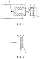
- Fig. 1 shows the basic structure of neutron radiography according to this embodiment.
- Fig. 2 shows an essential portion of an image pickup means of the neutron radiography.
- this embodiment has a structure that a radiation source is a neutron source 1.
- the neutron source 1 is accommodated in a moderator 2.
- Neutron beams emitted from the neutron source 1 sometimes contain X ray or ⁇ ray.
- a collimator 3 is disposed at a position which is irradiated with neutron beams.
- the neutron beams converged by the collimator 3 are used to irradiate a subject 4 to be measured.
- an image pickup cassette 5 serving as an image pickup means is disposed.
- the image pickup cassette 5 includes a detachable color film 6 which serves as a recording medium.
- the color film 6 has a first scintillator 7, a second scintillator 8 and a third scintillator 9 disposed sequentially.
- Each of the scintillators 7, 8 and 9 has a small thickness which permits penetration of each of light beams.
- the first scintillator 7 is made of a red-light emitting material having high sensitivity to the neutron, for example, gadolinium oxysulfide (Gd 2 O 2 S) activated with europium (Eu).
- the first scintillator 7 has a thickness of, for example, 40 mm.
- the second scintillator 8 is made of a green-light emitting material having high sensitivity to X ray, for example, gadolinium oxysulfide (Gd 2 O 2 S) activated with terbium (Tb).
- the second scintillator 8 has a thickness of, for example, tens of mm.
- the third scintillator 9 is made of a blue-light emitting material having high sensitivity to ⁇ ray, for example, zinc sulfide (ZnS) activated with silver (Ag).
- the third scintillator 9 has a thickness of, for example, tens of mm.
- the first, second and third scintillators 7, 8 and 9 may be made of the other light emitting members, and in this case, a function similar to that obtainable from this embodiment will be also realized.
- the colors of emitted light consisting of red, blue and green may be varied as described above.
- green and blue light emitted by the second and third scintillators 8 and 9 are allowed to pass through the first and second scintillators 7 and 8 so as to provide a film shape. At this time, the light is sensitized in a state in which information items of the scintillators are subtracted.
- Fig. 2 shows the structure that the color film 6 is disposed on the left-hand side which is the incident side for radioactive rays indicated with an arrow with respect to the scintillators 7, 8 and 9.
- the color film 6 may be disposed in the direction after the radioactive ray has been allowed to pass through, that is, on the right-hand side of the drawing.
- the color film 6 can be developed so as to be observed or digitally processed by a scanner or the like so as to be observed as images of the radiations in accordance with the wavelength. Therefore, combinations of the first, second and third scintillators 7, 8 and 9 for emitting light by the different radiations enable the recording of information on one color film in a short time, which has been impossible for the conventional structure, to be performed. Therefore, color images in accordance with the radiations can instantaneously be observed. As a result, the amount of the radiations with which the subject 4 to be measured is radiated can be reduced when an inspection is performed. Thus, the amount of exposure can be reduced and time required to complete the measurement can be shortened.
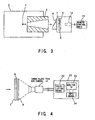
- This embodiment has a structure that the color film according to the first embodiment is replaced by a camera and an optical lens to directly observe an image.
- Fig. 3 shows the overall structure of the apparatus.
- Fig. 4 shows an essential portion of the apparatus.
- this embodiment has a structure incorporating a three-plate type CCD camera 14.
- information of first, second and third scintillators 7, 8 and 9 which emit light by dint of different radiations is obtainable as an image signal.
- the image signal can be monitored by a remote control unit 21 connected to the three-plate type CCD camera 14.
- the remote control unit 21 incorporates a calculating means 22 for performing subtraction in accordance with information of three types of color light, a monitor television (TV) set 23 which is capable of displaying a result of the calculation and an input means 24 for operation.
- TV monitor television
- this embodiment enables measurement to be performed through the remote control, the measurement can be performed without exposure of radioactive rays. Moreover, a time required for this measurement can be shortened. Since the observed signals are extracted as RGB signals, an image process can instantaneously be performed to correct fogging of X ray and ⁇ ray and irregular irradiation of the area which must be irradiated. Since separated observation in accordance with the color on the monitor television set 23 is permitted, an advantage can be realized in that alignment of images having different wavelengths can be omitted.
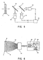
- Fig. 5 is a modification of the foregoing embodiment.
- the dichroic mirror 10 reflects a light beam emitted from the first scintillator 7 and permits penetration of light beams emitted from the second and third scintillators 8 and 9.
- the second dichroic mirror 11 reflects the light beam emitted from the second scintillator 8 and permits the light beam emitted from the third scintillator 9. Images by the different light beams can individually be observed by the third CCD camera 12.
- the above-mentioned structure enables the image obtained by each CCD camera 12 to independently be observed. Moreover, an image process can instantaneously be performed to correct fogging of X ray and ⁇ ray and irregular irradiation to the area which must be irradiated. Since the structure incorporates the dichroic mirrors for strictly separating only specific wavelength, the ratio (SIN) of noise with respect to a signal can be improved.
- the second embodiment mentioned above has the structure incorporating the CCD cameras and the optical lenses.
- This third embodiment incorporates an optical fiber in place of the optical lens.
- Fig. 6 shows an essential portion of the structure.
- this embodiment incorporates a number of optical fibers, for example, tapered fibers 13 which are bundled, each having a structure such that the cross sectional area of the light incident portion is larger than that of the light emission portion.
- the bundled tapered fibers 13 establish the direct connection between the third scintillator 9 and the light receiving surface of the CCD camera 14.
- Each of the foregoing embodiments may have a structure in which an image intensifies is interposed between the scintillator and the light receiving devices so as to improve the sensitivity.
- the materials for the scintillators may arbitrarily be employed in accordance with the subject or the environment.
Landscapes
- Physics & Mathematics (AREA)
- Health & Medical Sciences (AREA)
- Life Sciences & Earth Sciences (AREA)
- General Physics & Mathematics (AREA)
- High Energy & Nuclear Physics (AREA)
- Molecular Biology (AREA)
- Spectroscopy & Molecular Physics (AREA)
- Measurement Of Radiation (AREA)
Claims (17)
- Strahlungsunterscheidende Messvorrichtung, umfassend:eine Strahlungsquelle (1) zum Abstrahlen von Strahlungen,einen ersten, einen zweiten und einen dritten Szintillator (7, 8, 9), die in einem Bereich, der mit den Strahlungen bestrahlt wird, die von der Strahlungsquelle (1) abgestrahlt wird, zusammen mit einem zu messenden Gegenstand (4) angeordnet sind, wobei der erste Szintillator (7) angepasst ist, auf Strahlungen des Typs A, des Typs B und des Typs C, die von der Strahlungsquelle (1) abgestrahlt werden, so zu reagieren, dass ein Lichtstrahl in einem ersten Wellenlängenbereich emittiert wird, wobei der zweite Szintillator (8) angepasst ist, auf Strahlungen des Typs B und des Typs C, die durch den ersten Szintillator (7) hindurchtreten, so zu reagieren, dass ein Lichtstrahl in einem zweiten Wellenlängenbereich emittiert wird, und wobei der dritte Szintillator (9) angepasst ist, auf Strahlung des Typs C, die durch den zweiten Szintillator (8) hindurchtritt, so zu reagieren, dass ein Lichtstrahl in einem dritten Wellenlängenbereich, der von dem ersten und dem zweiten Wellenlängenbereich verschieden ist, emittiert wird, undeine Bilderfassungseinrichtung (12, 14), die auf einer Rückseite des zu messenden Gegenstands (4) angeordnet und angepasst ist, Lichtstrahlen, die von dem ersten, dem zweiten und dem dritten Szintillator (7, 8, 9) emittiert werden, gemäß dem Wellenlängenbereich zu erfassen und zu unterscheiden und gleichzeitig den Typ der Strahlungen zu messen.
- Strahlungsunterscheidende Messvorrichtung nach Anspruch 1, bei der Daten des ersten Szintillators (7) mit Daten des zweiten und des dritten Szintillators (8, 9) korrigiert werden und Daten des zweiten Szintillators (8) mit Daten des dritten Szintillators (9) korrigiert werden und die Bilderfassungseinrichtung (12, 14) den Typ der Strahlungen mit den korrigierten Daten von den Szintillatoren unterscheidet und misst.
- Strahlungsunterscheidende Messvorrichtung nach Anspruch 1 oder 2, bei der die Bilderfassungseinrichtung (14) einen Farbfilm umfasst, der die Strahlungen gemäß der Wellenlänge erfasst und aufzeichnet.
- Strahlungsunterscheidende Messvorrichtung nach Anspruch 1 oder 2, bei der die Bilderfassungseinrichtung (12, 14) einen Photodetektor zum Erfassen der Strahlungen gemäß der Wellenlänge umfasst, wobei vorzugsweise der Photodetektor eine CCD-Kamera ist oder der Photodetektor eine Bilderfassungsröhre ist.
- Strahlungsunterscheidende Messvorrichtung nach Anspruch 4, bei welcher der Photodetektor eine Mehrzahl monochromer CCD-Kameras (12), die für die jeweiligen Wellenlängen angepasst sind, und einen dichroitischen Spiegel (10, 11) zum Trennen von Wellenlängen von Lichtstrahlen, die von den Szintillatoren (7, 8, 9) emittiert werden, umfasst, oder bei welcher der Photodetektor eine Mehrzahl von Bilderfassungsröhren (12), die für die jeweiligen Wellenlängen angepasst sind, und einen dichroitischen Spiegel (10, 11) zum Trennen von Wellenlängen von Lichtstrahlen, die von den Szintillatoren (7, 8, 9) emittiert werden, umfasst.
- Strahlungsunterscheidende Messvorrichtung nach Anspruch 4, bei welcher der Photodetektor (14) getrennt von dem ersten, dem zweiten und dem dritten Szintillator (7, 8, 9) angeordnet ist und bei der die Messvorrichtung ferner eine Lichtleitfaser (13) zum Übertragen von Signalen von den Szintillatoren (7, 8, 9), die zwischen dem Photodetektor (14) und den Szintillatoren (7, 8, 9) angeordnet ist, umfasst.
- Strahlungsunterscheidende Messvorrichtung nach Anspruch 6, die ferner einen Bildverstärker zum Verstärken von Signalen von den Szintillatoren (7, 8, 9) und zum Verbessern der Empfindlichkeit umfasst, wobei der Bildverstärker anstelle der Lichtleitfaser (13) angeordnet ist, oder die ferner einen Bildverstärker zum Verstärken von Signalen von den Szintillatoren (7, 8, 9) und zum Verbessern der Empfindlichkeit umfasst, wobei der Bildverstärker zusammen mit der Lichtleitfaser (13) angeordnet ist.
- Strahlungsunterscheidende Messvorrichtung nach Anspruch 4, die ferner einen Bildverstärker zum Verstärken von Signalen von den Szintillatoren (7, 8, 9) und zum Verbessern der Empfindlichkeit umfasst, wobei der Bildverstärker an dem Photodetektor (14) angebracht ist.
- Strahlungsunterscheidende Messvorrichtung nach Anspruch 4, bei der die Bilderfassungseinrichtung (12, 14) mit einer Bilderfassungskassette des integrierten Typs mit abnehmbarem Film zum Aufnehmen eines Farbfilms und des ersten, des zweiten und des dritten Szintillators (7, 8, 9) ausgestattet ist.
- Strahlungsunterscheidende Messvorrichtung nach Anspruch 9, bei welcher der erste Szintillator (7) oder der zweite Szintillator (8) ein rotes oder grünes Licht emittierender Szintillator für thermische Neutronen ist und Wasserstoff-enthaltende Substanzen zwischen dem ersten Szintillator (7) und dem zweiten Szintillator (8) angeordnet sind.
- Strahlungsunterscheidende Messvorrichtung nach einem der Ansprüche 1 bis 10, bei der die Strahlung des Typs A α-Strahlung, die Strahlung des Typs B β-Strahlung und die Strahlung des Typs C γ-Strahlung ist, der erste Szintillator (7) ein blaues Licht emittierendes Element umfasst, der zweite Szintillator (8) ein rotes Licht emittierendes Element umfasst und der dritte Szintillator (9) ein grünes Licht emittierendes Element umfasst, und die α-, β- und γ-Strahlung gleichzeitig mittels Farbunterscheidung gemessen werden.
- Strahlungsunterscheidende Messvorrichtung nach einem der Ansprüche 1 bis 10, bei der die Strahlung des Typs A β-Strahlung, die Strahlung des Typs B Neutronenstrahlung und die Strahlung des Typs C γ-Strahlung ist, der erste Szintillator (7) ein blaues Licht emittierendes Element umfasst, der zweite Szintillator (8) ein rotes Licht emittierendes Element umfasst und der dritte Szintillator (9) ein grünes Licht emittierendes Element umfasst, und die β-, Neutronen- und γ-Strahlung gleichzeitig mittels Farbunterscheidung gemessen werden.
- Strahlungsunterscheidende Messvorrichtung nach Anspruch 11 oder 12, bei der die Kombination aus den Szintillatoren (7, 8, 9) eine Kombination ist, die derart ist, dass der erste Szintillator (7) ein blaues Licht emittierendes Element umfasst, der zweite Szintillator (8) ein grünes Licht emittierendes Element umfasst und der dritte Szintillator (9) ein rotes Licht emittierendes Element umfasst, oder eine Kombination aus Rot, Blau und Grün ist, oder eine Kombination aus Rot, Grün und Blau ist, oder eine Kombination aus Grün, Rot und Blau ist, oder eine Kombination aus Grün, Blau und Rot ist, und zwar in der Reihenfolge von dem ersten Szintillator (7) zu dem dritten Szintillator (9), so dass die Ergebnisse der Photographiervorgänge gemäß des Unterschieds bei der Kombination der Farben klassifiziert werden.
- Strahlungsunterscheidende Messvorrichtung nach Anspruch 11 oder 12, bei welcher der blaues Licht emittierende Szintillator einen Kunststoff-Szintillator, einen Glas-Szintillator oder einen Sinterkörper aus einem blaues Licht emittierenden Material umfasst, und/oder bei welcher der rotes Licht emittierende Szintillator einen Sinterkörper aus einem rot fluoreszierenden Material umfasst, das vorwiegend aus Gadolinium (Gd), das mit Europium (Eu) oder Chrom (Cr) aktiviert ist, zusammengesetzt ist, und/oder bei welcher der grünes Licht emittierende Szintillator einen Sinterkörper aus einem grün fluoreszierenden Material umfasst, das vorwiegend aus Gadolinium (Gd), das mit Praseodym (Pr) oder Terbium (Tb) aktiviert ist, zusammengesetzt ist.
- Strahlungsunterscheidende Messvorrichtung nach Anspruch 14, bei der das blau fluoreszierende Material jedwedes von Cer-aktiviertem Yttriumaluminat (YAlO3:Ce), Cer-aktiviertem Yttriumsilikat (Y2SiO5:Ce), Cer-aktiviertem Gadoliniumsilikat (Gd2SiO5:Ce), Niobaktiviertem Yttriumtantalat (YTaO4:Nb), Europium-aktiviertem Bariumfluorchlorid (BaFCl:Eu), Silber-aktiviertem Zinksulfid (ZnS:Ag), Calciumwolframat CaWO4, Cadmiumwolframat CdWO4, Zinkwolframat ZnWO4 oder Magnesiumwolframat MgWO4 ist, und/oder bei der das rot fluoreszierende Material jedwedes von Europium-aktiviertem Gadoliniumborat .(GdBO3:Eu), Europium-aktiviertem Gadoliniumoxid (Gd2O3:Eu), Europium-aktiviertem Gadoliniumoxysulfid (Gd2O2S:Eu), Europium-aktiviertem Gadoliniumaluminat (Gd3Al5O12:Eu), Europium-aktiviertem Gadoliniumgallat (Gd3Ga5O12:Eu), Europium-aktiviertem Gadoliniumvanadat (GdVO4:Eu), Cer- oder Chrom-aktiviertem Gadoliniumgallat (Gd3Ga5O12:Ce oder Cr) ist, und/oder bei der das grün fluoreszierende Material jedwedes von Terbium-aktiviertem Gadoliniumoxid (Gd2O3:Tb), Terbium-aktiviertem Gadoliniumoxysulfid (Gd2O2S:Tb), Praseodym-aktiviertem Gadoliniumoxysulfid (Gd2O2S:Pr), Terbium-aktiviertem Gadoliniumgallat (Gd3Ga5O12:Tb) und Terbium-aktiviertem Gadoliniumaluminat (Gd3Al5O12:Tb) ist.
- Strahlungsunterscheidende Messvorrichtung nach einem der Ansprüche 1 bis 15, bei der die Szintillatoren (7, 8, 9) Strukturen aufweisen, die derart sind, dass sie das Hindurchdringen von Wellenlängen von Lichtstrahlen, die von kombinierten Szintillatoren (7, 8, 9) emittiert werden, ermöglichen.
- Strahlungsunterscheidendes Messverfahren, das durch eine strahlungsunterscheidende Messvorrichtung durchgeführt wird, die eine Strahlungsquelle zum Abstrahlen von Strahlungen, einen ersten, einen zweiten und einen dritten Szintillator, die in einem Bereich, der mit den Strahlungen bestrahlt wird, die von der Strahlungsquelle abgestrahlt werden, angeordnet sind, und eine Bilderfassungseinrichtung zum Erfassen des Lichtstrahls, der von dem ersten, dem zweiten und dem dritten Szintillator emittiert wird, umfasst, wobei das Messverfahren die Schritte umfasst:Anordnen eines zu messenden Gegenstands,Anordnen des ersten, des zweiten und des dritten Szintillators in einem Bereich, der mit den Strahlungen bestrahlt wird, die von der Strahlungsquelle abgestrahlt werden,Bewirken, dass der erste Szintillator auf Strahlungen des Typs A, des Typs B und des Typs C, die von der Strahlungsquelle abgestrahlt werden, reagiert, und einen Lichtstrahl in einem ersten Wellenlängenbereich emittiert,Bewirken, dass der zweite Szintillator auf Strahlungen des Typs B und des Typs C, die durch den ersten Szintillator hindurchtreten, reagiert, so dass ein Lichtstrahl in einem zweiten Wellenlängenbereich emittiert wird,Bewirken, dass der dritte Szintillator auf eine Strahlung des Typs C, die durch den zweiten Szintillator hindurchtritt, reagiert, so dass ein Lichtstrahl in einem dritten Wellenlängenbereich, der von dem ersten und dem zweiten Wellenlängenbereich verschieden ist, emittiert wird,Erfassen der Lichtstrahlen, die von dem ersten, dem zweiten und dem dritten Szintillator emittiert werden, gemäß des Wellenlängenbereichs,Korrigieren von Daten des ersten Szintillators mit Daten des zweiten und des dritten Szintillators, undKorrigieren von Daten des zweiten Szintillators mit Daten des dritten Szintillators, so dass die Strahlungen gemäß des Typs der Strahlung gemäß der Wellenlänge unterschieden und gleichzeitig gemessen werden.
Applications Claiming Priority (2)
| Application Number | Priority Date | Filing Date | Title |
|---|---|---|---|
| JP9841098A JPH11271453A (ja) | 1998-03-25 | 1998-03-25 | 放射線弁別測定方法および放射線弁別測定装置 |
| JP9841098 | 1998-03-25 |
Publications (3)
| Publication Number | Publication Date |
|---|---|
| EP0947855A2 EP0947855A2 (de) | 1999-10-06 |
| EP0947855A3 EP0947855A3 (de) | 1999-10-13 |
| EP0947855B1 true EP0947855B1 (de) | 2005-11-23 |
Family
ID=14219069
Family Applications (1)
| Application Number | Title | Priority Date | Filing Date |
|---|---|---|---|
| EP99101584A Expired - Lifetime EP0947855B1 (de) | 1998-03-25 | 1999-01-29 | Vorrichtung und Verfahren zur simultanen Messung von unterschiedlichen Strahlungsarten |
Country Status (4)
| Country | Link |
|---|---|
| US (1) | US6313465B1 (de) |
| EP (1) | EP0947855B1 (de) |
| JP (1) | JPH11271453A (de) |
| DE (1) | DE69928465T2 (de) |
Families Citing this family (33)
| Publication number | Priority date | Publication date | Assignee | Title |
|---|---|---|---|---|
| DE69929027T2 (de) * | 1998-12-28 | 2006-08-24 | Kabushiki Kaisha Toshiba, Kawasaki | Strahlungsdetektoreinrichtung |
| US6630675B2 (en) * | 2000-07-26 | 2003-10-07 | Siemens Medical Solutions Usa, Inc. | X-ray scintillator compositions for X-ray imaging applications |
| US6566657B2 (en) * | 2001-03-14 | 2003-05-20 | Richard C. Odom | Geometrically optimized fast neutron detector |
| US6868236B2 (en) | 2002-07-18 | 2005-03-15 | Terabeam Corporation | Apparatus and method for combining multiple optical beams in a free-space optical communications system |
| EP1576355A2 (de) * | 2002-09-30 | 2005-09-21 | Applied Materials Israel Ltd. | Beleuchtungssystem für die optische inspektion |
| PT1558947E (pt) * | 2002-11-06 | 2012-03-05 | American Science & Eng Inc | Furgão de inspecção móvel com retro-difusão de raios-x |
| US6989541B2 (en) * | 2003-05-30 | 2006-01-24 | General Dynamics Advanced Information Systems, Inc. | Coincident neutron detector for providing energy and directional information |
| JP4208687B2 (ja) * | 2003-09-29 | 2009-01-14 | 株式会社東芝 | イメージセンサ |
| JP4415095B2 (ja) * | 2004-04-15 | 2010-02-17 | 独立行政法人 日本原子力研究開発機構 | ZnS蛍光体を用いた粒子線検出器及び中性子検出器 |
| RU2300120C1 (ru) * | 2005-09-28 | 2007-05-27 | Федеральное государственное унитарное предприятие "Всероссийский научно-исследовательский институт автоматики им. Н.Л. Духова" | Регистратор ионизирующих излучений |
| DE102006033662A1 (de) * | 2006-07-20 | 2008-01-24 | Forschungszentrum Dresden - Rossendorf E.V. | Verfahren zum Bestimmen einer Materialzusammensetzung einer Materialprobe |
| DE102006033661A1 (de) * | 2006-07-20 | 2008-01-24 | Forschungszentrum Dresden - Rossendorf E.V. | Detektoranordnung zur winkelauflösenden Detektion von Strahlung und Verfahren zum Betrieb desselben |
| KR101124549B1 (ko) * | 2007-04-24 | 2012-03-20 | 가부시끼가이샤 도시바 | 라디오그래피 측정 장치 및 라디오그래피 측정 방법 |
| CA2742127C (en) * | 2007-11-01 | 2017-01-24 | Rapiscan Security Products, Inc. | Multiple screen detection systems |
| CN102985847B (zh) | 2010-06-01 | 2016-03-02 | 圣戈本陶瓷及塑料股份有限公司 | 检测不同定向辐射的辐射传感器以及包含该辐射传感器的辐射检测系统 |
| JP5894916B2 (ja) * | 2010-07-21 | 2016-03-30 | 国立大学法人広島大学 | ホスウィッチ型熱中性子検出器 |
| CA2874397C (en) * | 2011-05-24 | 2019-09-24 | Universite Laval | Methods and apparatus for optically encoded position multiple-point scintillation detector using a single collecting light guide |
| ES1154460Y (es) * | 2012-02-14 | 2016-07-08 | American Science & Eng Inc | Dispositivo de portal de inspección por rayos X |
| EP2816376A1 (de) * | 2013-06-19 | 2014-12-24 | cynora GmbH | Verfahren zum Nachweis von Strahlung |
| EP3197983B1 (de) * | 2014-09-25 | 2023-06-07 | Koninklijke Philips N.V. | Erkennungsgerät zum erkennen von gamma- oder röntgenstrahlung |
| FR3027119B1 (fr) * | 2014-10-09 | 2016-12-23 | Commissariat Energie Atomique | Dispositif d'imagerie duale |
| GB2559500B (en) | 2015-09-10 | 2022-02-23 | American Science & Eng Inc | Backscatter characterization using interlinearly adaptive electromagnetic x-ray scanning |
| GB2560552B (en) * | 2017-03-15 | 2020-09-09 | Smiths Heimann Sas | Method and apparatus |
| CN110650777B (zh) * | 2017-05-16 | 2021-07-20 | 住友重机械工业株式会社 | 中子捕捉疗法系统 |
| CN107748170B (zh) * | 2017-11-01 | 2023-10-13 | 中国工程物理研究院激光聚变研究中心 | 中子和x射线双谱段成像相机 |
| JP6932619B2 (ja) * | 2017-11-10 | 2021-09-08 | 株式会社日立製作所 | 放射線モニタ、及び放射線の測定方法 |
| US10942283B2 (en) * | 2019-03-19 | 2021-03-09 | Secretary, Department Of Atomic Energy | Two single crystals based phoswich detector for discriminating various kinds of radiations |
| US11402516B2 (en) * | 2019-10-08 | 2022-08-02 | Lawrence Livermore National Security, Llc | System and method for neutron and gamma radiation detection using non-homogeneous material scintillator |
| CN110954937A (zh) * | 2019-12-04 | 2020-04-03 | 上海科润光电技术有限公司 | 一种快速检测χ射线的变色成像薄膜 |
| US11193898B1 (en) | 2020-06-01 | 2021-12-07 | American Science And Engineering, Inc. | Systems and methods for controlling image contrast in an X-ray system |
| JP7842413B2 (ja) * | 2021-08-12 | 2026-04-08 | 国立大学法人横浜国立大学 | 蛍光体とその製造方法 |
| CN115061183A (zh) * | 2022-05-20 | 2022-09-16 | 浙江大学 | 一种实现x射线多能谱成像的叠层闪烁体结构及成像设备 |
| FR3150294B1 (fr) * | 2023-06-23 | 2025-05-23 | Commissariat Energie Atomique | Dispositif et procédé de détermination d’un absorbant neutronique dans un objet |
Family Cites Families (17)
| Publication number | Priority date | Publication date | Assignee | Title |
|---|---|---|---|---|
| US4029963A (en) * | 1976-07-30 | 1977-06-14 | The Board Of Trustees Of Leland Stanford Junior University | X-ray spectral decomposition imaging system |
| JPS58113842A (ja) * | 1981-12-28 | 1983-07-06 | Japan Atom Energy Res Inst | ラジオグラフィー装置 |
| JPS60188869A (ja) * | 1984-03-09 | 1985-09-26 | Toshiba Corp | シンチレ−シヨン検出器 |
| JPS61184444A (ja) * | 1985-02-12 | 1986-08-18 | Nippon Atom Ind Group Co Ltd | 同時ラジオグラフイ− |
| JPH065291B2 (ja) * | 1986-07-02 | 1994-01-19 | 株式会社日立製作所 | 放射線検出器 |
| JPH05341047A (ja) * | 1991-05-22 | 1993-12-24 | Japan Atom Energy Res Inst | 効果的なα及びβ(γ)線同時測定法及びその検出器 |
| GB9115259D0 (en) * | 1991-07-15 | 1991-08-28 | Philips Electronic Associated | An image detector |
| US5317158A (en) | 1991-10-22 | 1994-05-31 | Martin Marietta Energy Systems, Inc. | Unitary scintillation detector and system |
| DE4224931C2 (de) * | 1992-07-28 | 1995-11-23 | Siemens Ag | Verfahren zur Herstellung einer Szintillatorkeramik und deren Verwendung |
| US5313065A (en) | 1992-09-01 | 1994-05-17 | The Babcock & Wilcox Company | Fiber optic radiation monitor |
| FR2700210B1 (fr) * | 1993-01-06 | 1995-02-10 | Commissariat Energie Atomique | Dispositif de détection simultanée et sélective de neutrons et de photons X ou gamma et système de détection utilisant ce dispositif. |
| JP2818730B2 (ja) | 1994-07-19 | 1998-10-30 | 日本原子力研究所 | 中性子画像形成方法 |
| US5548123A (en) * | 1994-12-06 | 1996-08-20 | Regents Of The University Of California | High resolution, multiple-energy linear sweep detector for x-ray imaging |
| JP3064218B2 (ja) * | 1995-07-10 | 2000-07-12 | アロカ株式会社 | 放射線測定装置 |
| JP3524300B2 (ja) * | 1995-11-21 | 2004-05-10 | 株式会社東芝 | セラミックスシンチレータ、それを用いた放射線検出器および放射線検査装置 |
| US5647368A (en) * | 1996-02-28 | 1997-07-15 | Xillix Technologies Corp. | Imaging system for detecting diseased tissue using native fluorsecence in the gastrointestinal and respiratory tract |
| JPH09236669A (ja) * | 1996-03-01 | 1997-09-09 | Tohoku Electric Power Co Inc | ファイバ型放射線検出器 |
-
1998
- 1998-03-25 JP JP9841098A patent/JPH11271453A/ja active Pending
-
1999
- 1999-01-29 DE DE69928465T patent/DE69928465T2/de not_active Expired - Lifetime
- 1999-01-29 US US09/239,967 patent/US6313465B1/en not_active Expired - Lifetime
- 1999-01-29 EP EP99101584A patent/EP0947855B1/de not_active Expired - Lifetime
Also Published As
| Publication number | Publication date |
|---|---|
| US6313465B1 (en) | 2001-11-06 |
| JPH11271453A (ja) | 1999-10-08 |
| DE69928465T2 (de) | 2006-08-03 |
| EP0947855A2 (de) | 1999-10-06 |
| EP0947855A3 (de) | 1999-10-13 |
| DE69928465D1 (de) | 2005-12-29 |
Similar Documents
| Publication | Publication Date | Title |
|---|---|---|
| EP0947855B1 (de) | Vorrichtung und Verfahren zur simultanen Messung von unterschiedlichen Strahlungsarten | |
| CN1886675B (zh) | 彩色闪烁器和图像传感器 | |
| JP2010181412A (ja) | 放射線弁別測定方法および放射線弁別測定装置 | |
| EP1550885B1 (de) | Leuchtstoffblatt für einen strahlungsdetektor; strahlungsdetektor damit und geräte zur detektion von strahlung | |
| JPS5915843A (ja) | 放射線構造解析方法 | |
| JP5060548B2 (ja) | ラジオグラフィ測定装置及びラジオグラフィ測定方法 | |
| JP2007327967A (ja) | 放射線弁別測定装置 | |
| JPS61184444A (ja) | 同時ラジオグラフイ− | |
| JP2000258539A (ja) | 放射線検出装置及び方法 | |
| JP2008051626A (ja) | ラインセンサ、ラインセンサユニット及び放射線非破壊検査システム | |
| CN102023308A (zh) | 基于具有辐射记忆功能的辐射光致发光图像板的辐射成像系统 | |
| JPH0513475B2 (de) | ||
| JP2006329905A (ja) | ラインセンサ、ラインセンサユニット及び放射線非破壊検査システム | |
| JPH05208000A (ja) | エネルギーサブトラクション画像作成装置 | |
| JP2000171598A (ja) | 蓄積性蛍光体シートとそれを用いた放射線弁別読取り装置および放射線弁別測定方法 | |
| JP2000304863A (ja) | 放射線検出用蛍光体シート | |
| JP3015685B2 (ja) | 輝尽発光物質を利用した放射線種弁別方法 | |
| JP2945547B2 (ja) | オートラジオグラム測定方法 | |
| US6066858A (en) | Autoradiographic process | |
| JPH0784053A (ja) | 放射線検出器およびその使用方法 | |
| JP2945548B2 (ja) | オートラジオグラム測定方法 | |
| JPH0829900A (ja) | 中性子画像形成方法 | |
| US20040227090A1 (en) | Dosimetry system | |
| JPS5910870A (ja) | 放射性同位元素検査方法 | |
| JPH0137726B2 (de) |
Legal Events
| Date | Code | Title | Description |
|---|---|---|---|
| PUAI | Public reference made under article 153(3) epc to a published international application that has entered the european phase |
Free format text: ORIGINAL CODE: 0009012 |
|
| PUAL | Search report despatched |
Free format text: ORIGINAL CODE: 0009013 |
|
| 17P | Request for examination filed |
Effective date: 19990129 |
|
| AK | Designated contracting states |
Kind code of ref document: A2 Designated state(s): CH DE FR GB LI |
|
| AX | Request for extension of the european patent |
Free format text: AL;LT;LV;MK;RO;SI |
|
| AK | Designated contracting states |
Kind code of ref document: A3 Designated state(s): AT BE CH CY DE DK ES FI FR GB GR IE IT LI LU MC NL PT SE |
|
| AX | Request for extension of the european patent |
Free format text: AL;LT;LV;MK;RO;SI |
|
| AKX | Designation fees paid |
Free format text: CH DE FR GB LI |
|
| 17Q | First examination report despatched |
Effective date: 20040322 |
|
| GRAP | Despatch of communication of intention to grant a patent |
Free format text: ORIGINAL CODE: EPIDOSNIGR1 |
|
| GRAS | Grant fee paid |
Free format text: ORIGINAL CODE: EPIDOSNIGR3 |
|
| GRAA | (expected) grant |
Free format text: ORIGINAL CODE: 0009210 |
|
| AK | Designated contracting states |
Kind code of ref document: B1 Designated state(s): CH DE FR GB LI |
|
| REG | Reference to a national code |
Ref country code: GB Ref legal event code: FG4D |
|
| REG | Reference to a national code |
Ref country code: CH Ref legal event code: EP |
|
| REF | Corresponds to: |
Ref document number: 69928465 Country of ref document: DE Date of ref document: 20051229 Kind code of ref document: P |
|
| REG | Reference to a national code |
Ref country code: CH Ref legal event code: NV Representative=s name: E. BLUM & CO. PATENTANWAELTE |
|
| ET | Fr: translation filed | ||
| PLBE | No opposition filed within time limit |
Free format text: ORIGINAL CODE: 0009261 |
|
| STAA | Information on the status of an ep patent application or granted ep patent |
Free format text: STATUS: NO OPPOSITION FILED WITHIN TIME LIMIT |
|
| 26N | No opposition filed |
Effective date: 20060824 |
|
| REG | Reference to a national code |
Ref country code: GB Ref legal event code: 746 Effective date: 20070317 |
|
| REG | Reference to a national code |
Ref country code: CH Ref legal event code: PFA Owner name: KABUSHIKI KAISHA TOSHIBA Free format text: KABUSHIKI KAISHA TOSHIBA#72, HORIKAWA-CHO SAIWAI-KU#KAWASAKI-SHI KANAGAWA-KEN TOKYO (JP) -TRANSFER TO- KABUSHIKI KAISHA TOSHIBA#72, HORIKAWA-CHO SAIWAI-KU#KAWASAKI-SHI KANAGAWA-KEN TOKYO (JP) |
|
| PGFP | Annual fee paid to national office [announced via postgrant information from national office to epo] |
Ref country code: CH Payment date: 20120112 Year of fee payment: 14 |
|
| PGFP | Annual fee paid to national office [announced via postgrant information from national office to epo] |
Ref country code: DE Payment date: 20120125 Year of fee payment: 14 |
|
| REG | Reference to a national code |
Ref country code: CH Ref legal event code: PL |
|
| PG25 | Lapsed in a contracting state [announced via postgrant information from national office to epo] |
Ref country code: CH Free format text: LAPSE BECAUSE OF NON-PAYMENT OF DUE FEES Effective date: 20130131 Ref country code: LI Free format text: LAPSE BECAUSE OF NON-PAYMENT OF DUE FEES Effective date: 20130131 Ref country code: DE Free format text: LAPSE BECAUSE OF NON-PAYMENT OF DUE FEES Effective date: 20130801 |
|
| REG | Reference to a national code |
Ref country code: DE Ref legal event code: R119 Ref document number: 69928465 Country of ref document: DE Effective date: 20130801 |
|
| PGFP | Annual fee paid to national office [announced via postgrant information from national office to epo] |
Ref country code: FR Payment date: 20140108 Year of fee payment: 16 |
|
| PGFP | Annual fee paid to national office [announced via postgrant information from national office to epo] |
Ref country code: GB Payment date: 20140129 Year of fee payment: 16 |
|
| GBPC | Gb: european patent ceased through non-payment of renewal fee |
Effective date: 20150129 |
|
| PG25 | Lapsed in a contracting state [announced via postgrant information from national office to epo] |
Ref country code: GB Free format text: LAPSE BECAUSE OF NON-PAYMENT OF DUE FEES Effective date: 20150129 |
|
| REG | Reference to a national code |
Ref country code: FR Ref legal event code: ST Effective date: 20150930 |
|
| PG25 | Lapsed in a contracting state [announced via postgrant information from national office to epo] |
Ref country code: FR Free format text: LAPSE BECAUSE OF NON-PAYMENT OF DUE FEES Effective date: 20150202 |