EP0947859B1 - Tinte, Farbfilter, Flüssigkristallanzeige und Computer, sowie Verfahren zur Herstellung des Farbfilters - Google Patents
Tinte, Farbfilter, Flüssigkristallanzeige und Computer, sowie Verfahren zur Herstellung des Farbfilters Download PDFInfo
- Publication number
- EP0947859B1 EP0947859B1 EP99106587A EP99106587A EP0947859B1 EP 0947859 B1 EP0947859 B1 EP 0947859B1 EP 99106587 A EP99106587 A EP 99106587A EP 99106587 A EP99106587 A EP 99106587A EP 0947859 B1 EP0947859 B1 EP 0947859B1
- Authority
- EP
- European Patent Office
- Prior art keywords
- ink
- color filter
- group
- base plate
- light
- Prior art date
- Legal status (The legal status is an assumption and is not a legal conclusion. Google has not performed a legal analysis and makes no representation as to the accuracy of the status listed.)
- Expired - Lifetime
Links
- 238000000034 method Methods 0.000 title claims description 56
- 239000004973 liquid crystal related substance Substances 0.000 title claims description 43
- 239000002585 base Substances 0.000 claims description 69
- 239000000975 dye Substances 0.000 claims description 65
- 239000011347 resin Substances 0.000 claims description 41
- 229920005989 resin Polymers 0.000 claims description 41
- JEXVQSWXXUJEMA-UHFFFAOYSA-N pyrazol-3-one Chemical compound O=C1C=CN=N1 JEXVQSWXXUJEMA-UHFFFAOYSA-N 0.000 claims description 40
- 229910052783 alkali metal Inorganic materials 0.000 claims description 19
- 150000001340 alkali metals Chemical class 0.000 claims description 19
- 239000000463 material Substances 0.000 claims description 19
- 125000000217 alkyl group Chemical group 0.000 claims description 18
- 125000001273 sulfonato group Chemical group [O-]S(*)(=O)=O 0.000 claims description 16
- 125000004435 hydrogen atom Chemical group [H]* 0.000 claims description 14
- 239000001007 phthalocyanine dye Substances 0.000 claims description 12
- 125000004432 carbon atom Chemical group C* 0.000 claims description 11
- 125000000449 nitro group Chemical group [O-][N+](*)=O 0.000 claims description 9
- 125000002887 hydroxy group Chemical group [H]O* 0.000 claims description 8
- 150000001875 compounds Chemical class 0.000 claims description 7
- 125000005843 halogen group Chemical group 0.000 claims description 7
- 239000000178 monomer Substances 0.000 claims description 7
- 229920000642 polymer Polymers 0.000 claims description 4
- 239000002904 solvent Substances 0.000 claims description 4
- NIXOWILDQLNWCW-UHFFFAOYSA-N acrylic acid group Chemical group C(C=C)(=O)O NIXOWILDQLNWCW-UHFFFAOYSA-N 0.000 claims description 3
- 125000003368 amide group Chemical group 0.000 claims description 3
- 238000009835 boiling Methods 0.000 claims description 3
- 125000003178 carboxy group Chemical group [H]OC(*)=O 0.000 claims description 3
- 229910052802 copper Inorganic materials 0.000 claims description 3
- 229910052759 nickel Inorganic materials 0.000 claims description 3
- IEQIEDJGQAUEQZ-UHFFFAOYSA-N phthalocyanine Chemical group N1C(N=C2C3=CC=CC=C3C(N=C3C4=CC=CC=C4C(=N4)N3)=N2)=C(C=CC=C2)C2=C1N=C1C2=CC=CC=C2C4=N1 IEQIEDJGQAUEQZ-UHFFFAOYSA-N 0.000 claims description 3
- 229910052725 zinc Inorganic materials 0.000 claims description 3
- 229920003169 water-soluble polymer Polymers 0.000 claims description 2
- 239000000976 ink Substances 0.000 description 123
- 238000011156 evaluation Methods 0.000 description 34
- 239000011159 matrix material Substances 0.000 description 24
- 230000015572 biosynthetic process Effects 0.000 description 16
- 238000010438 heat treatment Methods 0.000 description 15
- 238000004519 manufacturing process Methods 0.000 description 14
- 239000000203 mixture Substances 0.000 description 14
- 239000011734 sodium Substances 0.000 description 14
- 230000000740 bleeding effect Effects 0.000 description 12
- 239000010408 film Substances 0.000 description 11
- 238000004040 coloring Methods 0.000 description 9
- 238000009472 formulation Methods 0.000 description 8
- 239000003795 chemical substances by application Substances 0.000 description 7
- -1 polyvinylacetal Polymers 0.000 description 7
- XLYOFNOQVPJJNP-UHFFFAOYSA-N water Substances O XLYOFNOQVPJJNP-UHFFFAOYSA-N 0.000 description 7
- LFQSCWFLJHTTHZ-UHFFFAOYSA-N Ethanol Chemical compound CCO LFQSCWFLJHTTHZ-UHFFFAOYSA-N 0.000 description 6
- LYCAIKOWRPUZTN-UHFFFAOYSA-N Ethylene glycol Chemical compound OCCO LYCAIKOWRPUZTN-UHFFFAOYSA-N 0.000 description 6
- 230000000052 comparative effect Effects 0.000 description 6
- 239000000049 pigment Substances 0.000 description 6
- 238000004043 dyeing Methods 0.000 description 5
- 239000011521 glass Substances 0.000 description 5
- 239000003960 organic solvent Substances 0.000 description 5
- 229910052700 potassium Inorganic materials 0.000 description 5
- 239000011342 resin composition Substances 0.000 description 5
- 239000004925 Acrylic resin Substances 0.000 description 4
- 229920000178 Acrylic resin Polymers 0.000 description 4
- 229910003202 NH4 Inorganic materials 0.000 description 4
- 239000000654 additive Substances 0.000 description 4
- 239000003086 colorant Substances 0.000 description 4
- 238000001723 curing Methods 0.000 description 4
- 229910052744 lithium Inorganic materials 0.000 description 4
- 230000003287 optical effect Effects 0.000 description 4
- 229910052708 sodium Inorganic materials 0.000 description 4
- 238000004528 spin coating Methods 0.000 description 4
- 125000000391 vinyl group Chemical group [H]C([*])=C([H])[H] 0.000 description 4
- 229920002554 vinyl polymer Polymers 0.000 description 4
- POAOYUHQDCAZBD-UHFFFAOYSA-N 2-butoxyethanol Chemical compound CCCCOCCO POAOYUHQDCAZBD-UHFFFAOYSA-N 0.000 description 3
- WVDDGKGOMKODPV-UHFFFAOYSA-N Benzyl alcohol Chemical compound OCC1=CC=CC=C1 WVDDGKGOMKODPV-UHFFFAOYSA-N 0.000 description 3
- ZMXDDKWLCZADIW-UHFFFAOYSA-N N,N-Dimethylformamide Chemical compound CN(C)C=O ZMXDDKWLCZADIW-UHFFFAOYSA-N 0.000 description 3
- 239000012736 aqueous medium Substances 0.000 description 3
- ZBNARPCCDMHDDV-UHFFFAOYSA-N chembl1206040 Chemical compound C1=C(S(O)(=O)=O)C=C2C=C(S(O)(=O)=O)C(N=NC3=CC=C(C=C3C)C=3C=C(C(=CC=3)N=NC=3C(=CC4=CC(=CC(N)=C4C=3O)S(O)(=O)=O)S(O)(=O)=O)C)=C(O)C2=C1N ZBNARPCCDMHDDV-UHFFFAOYSA-N 0.000 description 3
- 238000000576 coating method Methods 0.000 description 3
- MTHSVFCYNBDYFN-UHFFFAOYSA-N diethylene glycol Chemical compound OCCOCCO MTHSVFCYNBDYFN-UHFFFAOYSA-N 0.000 description 3
- 235000019441 ethanol Nutrition 0.000 description 3
- XPFVYQJUAUNWIW-UHFFFAOYSA-N furfuryl alcohol Chemical compound OCC1=CC=CO1 XPFVYQJUAUNWIW-UHFFFAOYSA-N 0.000 description 3
- 239000003999 initiator Substances 0.000 description 3
- 238000000386 microscopy Methods 0.000 description 3
- 238000000206 photolithography Methods 0.000 description 3
- 238000007639 printing Methods 0.000 description 3
- 150000003839 salts Chemical class 0.000 description 3
- 239000007787 solid Substances 0.000 description 3
- 238000004544 sputter deposition Methods 0.000 description 3
- 238000003860 storage Methods 0.000 description 3
- PUPZLCDOIYMWBV-UHFFFAOYSA-N (+/-)-1,3-Butanediol Chemical compound CC(O)CCO PUPZLCDOIYMWBV-UHFFFAOYSA-N 0.000 description 2
- 229920002818 (Hydroxyethyl)methacrylate Polymers 0.000 description 2
- BBMCTIGTTCKYKF-UHFFFAOYSA-N 1-heptanol Chemical compound CCCCCCCO BBMCTIGTTCKYKF-UHFFFAOYSA-N 0.000 description 2
- CETWDUZRCINIHU-UHFFFAOYSA-N 2-heptanol Chemical compound CCCCCC(C)O CETWDUZRCINIHU-UHFFFAOYSA-N 0.000 description 2
- SVTBMSDMJJWYQN-UHFFFAOYSA-N 2-methylpentane-2,4-diol Chemical compound CC(O)CC(C)(C)O SVTBMSDMJJWYQN-UHFFFAOYSA-N 0.000 description 2
- QCAHUFWKIQLBNB-UHFFFAOYSA-N 3-(3-methoxypropoxy)propan-1-ol Chemical compound COCCCOCCCO QCAHUFWKIQLBNB-UHFFFAOYSA-N 0.000 description 2
- HTSABYAWKQAHBT-UHFFFAOYSA-N 3-methylcyclohexanol Chemical compound CC1CCCC(O)C1 HTSABYAWKQAHBT-UHFFFAOYSA-N 0.000 description 2
- YEJRWHAVMIAJKC-UHFFFAOYSA-N 4-Butyrolactone Chemical compound O=C1CCCO1 YEJRWHAVMIAJKC-UHFFFAOYSA-N 0.000 description 2
- MQWCXKGKQLNYQG-UHFFFAOYSA-N 4-methylcyclohexan-1-ol Chemical compound CC1CCC(O)CC1 MQWCXKGKQLNYQG-UHFFFAOYSA-N 0.000 description 2
- DLFVBJFMPXGRIB-UHFFFAOYSA-N Acetamide Chemical compound CC(N)=O DLFVBJFMPXGRIB-UHFFFAOYSA-N 0.000 description 2
- VVJKKWFAADXIJK-UHFFFAOYSA-N Allylamine Chemical compound NCC=C VVJKKWFAADXIJK-UHFFFAOYSA-N 0.000 description 2
- 0 C*CC=CC(N)=C*=* Chemical compound C*CC=CC(N)=C*=* 0.000 description 2
- VYZAMTAEIAYCRO-UHFFFAOYSA-N Chromium Chemical compound [Cr] VYZAMTAEIAYCRO-UHFFFAOYSA-N 0.000 description 2
- ZHNUHDYFZUAESO-UHFFFAOYSA-N Formamide Chemical compound NC=O ZHNUHDYFZUAESO-UHFFFAOYSA-N 0.000 description 2
- RZKSECIXORKHQS-UHFFFAOYSA-N Heptan-3-ol Chemical compound CCCCC(O)CC RZKSECIXORKHQS-UHFFFAOYSA-N 0.000 description 2
- WOBHKFSMXKNTIM-UHFFFAOYSA-N Hydroxyethyl methacrylate Chemical compound CC(=C)C(=O)OCCO WOBHKFSMXKNTIM-UHFFFAOYSA-N 0.000 description 2
- 229920002153 Hydroxypropyl cellulose Polymers 0.000 description 2
- 229920000877 Melamine resin Polymers 0.000 description 2
- BAPJBEWLBFYGME-UHFFFAOYSA-N Methyl acrylate Chemical compound COC(=O)C=C BAPJBEWLBFYGME-UHFFFAOYSA-N 0.000 description 2
- CNCOEDDPFOAUMB-UHFFFAOYSA-N N-Methylolacrylamide Chemical compound OCNC(=O)C=C CNCOEDDPFOAUMB-UHFFFAOYSA-N 0.000 description 2
- ATHHXGZTWNVVOU-UHFFFAOYSA-N N-methylformamide Chemical compound CNC=O ATHHXGZTWNVVOU-UHFFFAOYSA-N 0.000 description 2
- VYPSYNLAJGMNEJ-UHFFFAOYSA-N Silicium dioxide Chemical compound O=[Si]=O VYPSYNLAJGMNEJ-UHFFFAOYSA-N 0.000 description 2
- YIQKLZYTHXTDDT-UHFFFAOYSA-H Sirius red F3B Chemical compound C1=CC(=CC=C1N=NC2=CC(=C(C=C2)N=NC3=C(C=C4C=C(C=CC4=C3[O-])NC(=O)NC5=CC6=CC(=C(C(=C6C=C5)[O-])N=NC7=C(C=C(C=C7)N=NC8=CC=C(C=C8)S(=O)(=O)[O-])S(=O)(=O)[O-])S(=O)(=O)O)S(=O)(=O)O)S(=O)(=O)[O-])S(=O)(=O)[O-].[Na+].[Na+].[Na+].[Na+].[Na+].[Na+] YIQKLZYTHXTDDT-UHFFFAOYSA-H 0.000 description 2
- 229920002472 Starch Polymers 0.000 description 2
- PPBRXRYQALVLMV-UHFFFAOYSA-N Styrene Chemical compound C=CC1=CC=CC=C1 PPBRXRYQALVLMV-UHFFFAOYSA-N 0.000 description 2
- 150000001252 acrylic acid derivatives Chemical class 0.000 description 2
- MWPLVEDNUUSJAV-UHFFFAOYSA-N anthracene Chemical compound C1=CC=CC2=CC3=CC=CC=C3C=C21 MWPLVEDNUUSJAV-UHFFFAOYSA-N 0.000 description 2
- WERYXYBDKMZEQL-UHFFFAOYSA-N butane-1,4-diol Chemical compound OCCCCO WERYXYBDKMZEQL-UHFFFAOYSA-N 0.000 description 2
- 125000002091 cationic group Chemical group 0.000 description 2
- 229910052804 chromium Inorganic materials 0.000 description 2
- 239000011651 chromium Substances 0.000 description 2
- 239000011248 coating agent Substances 0.000 description 2
- NKLPQNGYXWVELD-UHFFFAOYSA-M coomassie brilliant blue Chemical compound [Na+].C1=CC(OCC)=CC=C1NC1=CC=C(C(=C2C=CC(C=C2)=[N+](CC)CC=2C=C(C=CC=2)S([O-])(=O)=O)C=2C=CC(=CC=2)N(CC)CC=2C=C(C=CC=2)S([O-])(=O)=O)C=C1 NKLPQNGYXWVELD-UHFFFAOYSA-M 0.000 description 2
- 229920001577 copolymer Polymers 0.000 description 2
- MWKFXSUHUHTGQN-UHFFFAOYSA-N decan-1-ol Chemical compound CCCCCCCCCCO MWKFXSUHUHTGQN-UHFFFAOYSA-N 0.000 description 2
- SWXVUIWOUIDPGS-UHFFFAOYSA-N diacetone alcohol Chemical compound CC(=O)CC(C)(C)O SWXVUIWOUIDPGS-UHFFFAOYSA-N 0.000 description 2
- 238000010586 diagram Methods 0.000 description 2
- 238000002845 discoloration Methods 0.000 description 2
- 238000001035 drying Methods 0.000 description 2
- 238000004070 electrodeposition Methods 0.000 description 2
- 239000003822 epoxy resin Substances 0.000 description 2
- LNEPOXFFQSENCJ-UHFFFAOYSA-N haloperidol Chemical compound C1CC(O)(C=2C=CC(Cl)=CC=2)CCN1CCCC(=O)C1=CC=C(F)C=C1 LNEPOXFFQSENCJ-UHFFFAOYSA-N 0.000 description 2
- ZSIAUFGUXNUGDI-UHFFFAOYSA-N hexan-1-ol Chemical compound CCCCCCO ZSIAUFGUXNUGDI-UHFFFAOYSA-N 0.000 description 2
- 239000001863 hydroxypropyl cellulose Substances 0.000 description 2
- 235000010977 hydroxypropyl cellulose Nutrition 0.000 description 2
- 239000002609 medium Substances 0.000 description 2
- ZWRUINPWMLAQRD-UHFFFAOYSA-N nonan-1-ol Chemical compound CCCCCCCCCO ZWRUINPWMLAQRD-UHFFFAOYSA-N 0.000 description 2
- SJWFXCIHNDVPSH-UHFFFAOYSA-N octan-2-ol Chemical compound CCCCCCC(C)O SJWFXCIHNDVPSH-UHFFFAOYSA-N 0.000 description 2
- 238000000059 patterning Methods 0.000 description 2
- 229920000647 polyepoxide Polymers 0.000 description 2
- 238000003892 spreading Methods 0.000 description 2
- 239000008107 starch Substances 0.000 description 2
- 235000019698 starch Nutrition 0.000 description 2
- 239000004094 surface-active agent Substances 0.000 description 2
- 229920001187 thermosetting polymer Polymers 0.000 description 2
- 238000002834 transmittance Methods 0.000 description 2
- 150000003918 triazines Chemical class 0.000 description 2
- KJIOQYGWTQBHNH-UHFFFAOYSA-N undecanol Chemical compound CCCCCCCCCCCO KJIOQYGWTQBHNH-UHFFFAOYSA-N 0.000 description 2
- 238000007740 vapor deposition Methods 0.000 description 2
- 230000037303 wrinkles Effects 0.000 description 2
- 229910052724 xenon Inorganic materials 0.000 description 2
- FHNFHKCVQCLJFQ-UHFFFAOYSA-N xenon atom Chemical compound [Xe] FHNFHKCVQCLJFQ-UHFFFAOYSA-N 0.000 description 2
- DNIAPMSPPWPWGF-VKHMYHEASA-N (+)-propylene glycol Chemical compound C[C@H](O)CO DNIAPMSPPWPWGF-VKHMYHEASA-N 0.000 description 1
- NMRPBPVERJPACX-UHFFFAOYSA-N (3S)-octan-3-ol Natural products CCCCCC(O)CC NMRPBPVERJPACX-UHFFFAOYSA-N 0.000 description 1
- DNIAPMSPPWPWGF-GSVOUGTGSA-N (R)-(-)-Propylene glycol Chemical compound C[C@@H](O)CO DNIAPMSPPWPWGF-GSVOUGTGSA-N 0.000 description 1
- WUOACPNHFRMFPN-SECBINFHSA-N (S)-(-)-alpha-terpineol Chemical compound CC1=CC[C@@H](C(C)(C)O)CC1 WUOACPNHFRMFPN-SECBINFHSA-N 0.000 description 1
- ORTVZLZNOYNASJ-UPHRSURJSA-N (z)-but-2-ene-1,4-diol Chemical compound OC\C=C/CO ORTVZLZNOYNASJ-UPHRSURJSA-N 0.000 description 1
- XBYRMPXUBGMOJC-UHFFFAOYSA-N 1,2-dihydropyrazol-3-one Chemical compound OC=1C=CNN=1 XBYRMPXUBGMOJC-UHFFFAOYSA-N 0.000 description 1
- YPFDHNVEDLHUCE-UHFFFAOYSA-N 1,3-propanediol Substances OCCCO YPFDHNVEDLHUCE-UHFFFAOYSA-N 0.000 description 1
- 239000005968 1-Decanol Substances 0.000 description 1
- VTBOTOBFGSVRMA-UHFFFAOYSA-N 1-Methylcyclohexanol Chemical compound CC1(O)CCCCC1 VTBOTOBFGSVRMA-UHFFFAOYSA-N 0.000 description 1
- IXPNQXFRVYWDDI-UHFFFAOYSA-N 1-methyl-2,4-dioxo-1,3-diazinane-5-carboximidamide Chemical compound CN1CC(C(N)=N)C(=O)NC1=O IXPNQXFRVYWDDI-UHFFFAOYSA-N 0.000 description 1
- KMZHZAAOEWVPSE-UHFFFAOYSA-N 2,3-dihydroxypropyl acetate Chemical compound CC(=O)OCC(O)CO KMZHZAAOEWVPSE-UHFFFAOYSA-N 0.000 description 1
- VXQBJTKSVGFQOL-UHFFFAOYSA-N 2-(2-butoxyethoxy)ethyl acetate Chemical compound CCCCOCCOCCOC(C)=O VXQBJTKSVGFQOL-UHFFFAOYSA-N 0.000 description 1
- FPZWZCWUIYYYBU-UHFFFAOYSA-N 2-(2-ethoxyethoxy)ethyl acetate Chemical compound CCOCCOCCOC(C)=O FPZWZCWUIYYYBU-UHFFFAOYSA-N 0.000 description 1
- SMZOUWXMTYCWNB-UHFFFAOYSA-N 2-(2-methoxy-5-methylphenyl)ethanamine Chemical compound COC1=CC=C(C)C=C1CCN SMZOUWXMTYCWNB-UHFFFAOYSA-N 0.000 description 1
- SBASXUCJHJRPEV-UHFFFAOYSA-N 2-(2-methoxyethoxy)ethanol Chemical compound COCCOCCO SBASXUCJHJRPEV-UHFFFAOYSA-N 0.000 description 1
- NCHBYORVPVDWBJ-UHFFFAOYSA-N 2-(3-methylbutoxy)ethanol Chemical compound CC(C)CCOCCO NCHBYORVPVDWBJ-UHFFFAOYSA-N 0.000 description 1
- INFFATMFXZFLAO-UHFFFAOYSA-N 2-(methoxymethoxy)ethanol Chemical compound COCOCCO INFFATMFXZFLAO-UHFFFAOYSA-N 0.000 description 1
- HZAXFHJVJLSVMW-UHFFFAOYSA-N 2-Aminoethan-1-ol Chemical compound NCCO HZAXFHJVJLSVMW-UHFFFAOYSA-N 0.000 description 1
- RWLALWYNXFYRGW-UHFFFAOYSA-N 2-Ethyl-1,3-hexanediol Chemical compound CCCC(O)C(CC)CO RWLALWYNXFYRGW-UHFFFAOYSA-N 0.000 description 1
- WOFPPJOZXUTRAU-UHFFFAOYSA-N 2-Ethyl-1-hexanol Natural products CCCCC(O)CCC WOFPPJOZXUTRAU-UHFFFAOYSA-N 0.000 description 1
- WAEVWDZKMBQDEJ-UHFFFAOYSA-N 2-[2-(2-methoxypropoxy)propoxy]propan-1-ol Chemical compound COC(C)COC(C)COC(C)CO WAEVWDZKMBQDEJ-UHFFFAOYSA-N 0.000 description 1
- JTXMVXSTHSMVQF-UHFFFAOYSA-N 2-acetyloxyethyl acetate Chemical compound CC(=O)OCCOC(C)=O JTXMVXSTHSMVQF-UHFFFAOYSA-N 0.000 description 1
- NQBXSWAWVZHKBZ-UHFFFAOYSA-N 2-butoxyethyl acetate Chemical compound CCCCOCCOC(C)=O NQBXSWAWVZHKBZ-UHFFFAOYSA-N 0.000 description 1
- BFSVOASYOCHEOV-UHFFFAOYSA-N 2-diethylaminoethanol Chemical compound CCN(CC)CCO BFSVOASYOCHEOV-UHFFFAOYSA-N 0.000 description 1
- SVONRAPFKPVNKG-UHFFFAOYSA-N 2-ethoxyethyl acetate Chemical compound CCOCCOC(C)=O SVONRAPFKPVNKG-UHFFFAOYSA-N 0.000 description 1
- YIWUKEYIRIRTPP-UHFFFAOYSA-N 2-ethylhexan-1-ol Chemical compound CCCCC(CC)CO YIWUKEYIRIRTPP-UHFFFAOYSA-N 0.000 description 1
- UPGSWASWQBLSKZ-UHFFFAOYSA-N 2-hexoxyethanol Chemical compound CCCCCCOCCO UPGSWASWQBLSKZ-UHFFFAOYSA-N 0.000 description 1
- HXDLWJWIAHWIKI-UHFFFAOYSA-N 2-hydroxyethyl acetate Chemical compound CC(=O)OCCO HXDLWJWIAHWIKI-UHFFFAOYSA-N 0.000 description 1
- OMIGHNLMNHATMP-UHFFFAOYSA-N 2-hydroxyethyl prop-2-enoate Chemical compound OCCOC(=O)C=C OMIGHNLMNHATMP-UHFFFAOYSA-N 0.000 description 1
- NDVWOBYBJYUSMF-UHFFFAOYSA-N 2-methylcyclohexan-1-ol Chemical compound CC1CCCCC1O NDVWOBYBJYUSMF-UHFFFAOYSA-N 0.000 description 1
- QCDWFXQBSFUVSP-UHFFFAOYSA-N 2-phenoxyethanol Chemical compound OCCOC1=CC=CC=C1 QCDWFXQBSFUVSP-UHFFFAOYSA-N 0.000 description 1
- BODRLKRKPXBDBN-UHFFFAOYSA-N 3,5,5-Trimethyl-1-hexanol Chemical compound OCCC(C)CC(C)(C)C BODRLKRKPXBDBN-UHFFFAOYSA-N 0.000 description 1
- JTAXUBKTCAOMTN-UHFFFAOYSA-N Abietinol Natural products CC(C)C1=CC2C=CC3C(C)(CO)CCCC3(C)C2CC1 JTAXUBKTCAOMTN-UHFFFAOYSA-N 0.000 description 1
- HRPVXLWXLXDGHG-UHFFFAOYSA-N Acrylamide Chemical compound NC(=O)C=C HRPVXLWXLXDGHG-UHFFFAOYSA-N 0.000 description 1
- NLHHRLWOUZZQLW-UHFFFAOYSA-N Acrylonitrile Chemical compound C=CC#N NLHHRLWOUZZQLW-UHFFFAOYSA-N 0.000 description 1
- 102000009027 Albumins Human genes 0.000 description 1
- 108010088751 Albumins Proteins 0.000 description 1
- BEVOWZNDQZIWMP-QMMMGPOBSA-N CCC1=C(C)C2=C1C(C)=C(C)[C@@H]2C Chemical compound CCC1=C(C)C2=C1C(C)=C(C)[C@@H]2C BEVOWZNDQZIWMP-QMMMGPOBSA-N 0.000 description 1
- 229920002134 Carboxymethyl cellulose Polymers 0.000 description 1
- 108010076119 Caseins Proteins 0.000 description 1
- 239000004593 Epoxy Substances 0.000 description 1
- JIGUQPWFLRLWPJ-UHFFFAOYSA-N Ethyl acrylate Chemical compound CCOC(=O)C=C JIGUQPWFLRLWPJ-UHFFFAOYSA-N 0.000 description 1
- KMTRUDSVKNLOMY-UHFFFAOYSA-N Ethylene carbonate Chemical compound O=C1OCCO1 KMTRUDSVKNLOMY-UHFFFAOYSA-N 0.000 description 1
- 108010010803 Gelatin Proteins 0.000 description 1
- 229920000084 Gum arabic Polymers 0.000 description 1
- 229920000663 Hydroxyethyl cellulose Polymers 0.000 description 1
- 239000004354 Hydroxyethyl cellulose Substances 0.000 description 1
- 229920001479 Hydroxyethyl methyl cellulose Polymers 0.000 description 1
- 239000004640 Melamine resin Substances 0.000 description 1
- CERQOIWHTDAKMF-UHFFFAOYSA-N Methacrylic acid Chemical compound CC(=C)C(O)=O CERQOIWHTDAKMF-UHFFFAOYSA-N 0.000 description 1
- VVQNEPGJFQJSBK-UHFFFAOYSA-N Methyl methacrylate Chemical compound COC(=O)C(C)=C VVQNEPGJFQJSBK-UHFFFAOYSA-N 0.000 description 1
- FXHOOIRPVKKKFG-UHFFFAOYSA-N N,N-Dimethylacetamide Chemical compound CN(C)C(C)=O FXHOOIRPVKKKFG-UHFFFAOYSA-N 0.000 description 1
- SUAKHGWARZSWIH-UHFFFAOYSA-N N,N‐diethylformamide Chemical compound CCN(CC)C=O SUAKHGWARZSWIH-UHFFFAOYSA-N 0.000 description 1
- SECXISVLQFMRJM-UHFFFAOYSA-N N-Methylpyrrolidone Chemical compound CN1CCCC1=O SECXISVLQFMRJM-UHFFFAOYSA-N 0.000 description 1
- OHLUUHNLEMFGTQ-UHFFFAOYSA-N N-methylacetamide Chemical compound CNC(C)=O OHLUUHNLEMFGTQ-UHFFFAOYSA-N 0.000 description 1
- ALQSHHUCVQOPAS-UHFFFAOYSA-N Pentane-1,5-diol Chemical compound OCCCCCO ALQSHHUCVQOPAS-UHFFFAOYSA-N 0.000 description 1
- 239000004372 Polyvinyl alcohol Substances 0.000 description 1
- 241000978776 Senegalia senegal Species 0.000 description 1
- WGLPBDUCMAPZCE-UHFFFAOYSA-N Trioxochromium Chemical compound O=[Cr](=O)=O WGLPBDUCMAPZCE-UHFFFAOYSA-N 0.000 description 1
- XTXRWKRVRITETP-UHFFFAOYSA-N Vinyl acetate Chemical compound CC(=O)OC=C XTXRWKRVRITETP-UHFFFAOYSA-N 0.000 description 1
- 239000001089 [(2R)-oxolan-2-yl]methanol Substances 0.000 description 1
- MBHRHUJRKGNOKX-UHFFFAOYSA-N [(4,6-diamino-1,3,5-triazin-2-yl)amino]methanol Chemical compound NC1=NC(N)=NC(NCO)=N1 MBHRHUJRKGNOKX-UHFFFAOYSA-N 0.000 description 1
- GQRUHVMVWNKUFW-LWYYNNOASA-N abieta-7,13-dien-18-ol Chemical compound OC[C@]1(C)CCC[C@]2(C)[C@@H](CCC(C(C)C)=C3)C3=CC[C@H]21 GQRUHVMVWNKUFW-LWYYNNOASA-N 0.000 description 1
- 239000006096 absorbing agent Substances 0.000 description 1
- 238000010521 absorption reaction Methods 0.000 description 1
- 235000010489 acacia gum Nutrition 0.000 description 1
- 239000000205 acacia gum Substances 0.000 description 1
- 230000000996 additive effect Effects 0.000 description 1
- XYLMUPLGERFSHI-UHFFFAOYSA-N alpha-Methylstyrene Chemical compound CC(=C)C1=CC=CC=C1 XYLMUPLGERFSHI-UHFFFAOYSA-N 0.000 description 1
- OVKDFILSBMEKLT-UHFFFAOYSA-N alpha-Terpineol Natural products CC(=C)C1(O)CCC(C)=CC1 OVKDFILSBMEKLT-UHFFFAOYSA-N 0.000 description 1
- 229940088601 alpha-terpineol Drugs 0.000 description 1
- 125000000129 anionic group Chemical group 0.000 description 1
- 239000002518 antifoaming agent Substances 0.000 description 1
- 239000003963 antioxidant agent Substances 0.000 description 1
- 238000000149 argon plasma sintering Methods 0.000 description 1
- QVGXLLKOCUKJST-UHFFFAOYSA-N atomic oxygen Chemical compound [O] QVGXLLKOCUKJST-UHFFFAOYSA-N 0.000 description 1
- 235000019445 benzyl alcohol Nutrition 0.000 description 1
- BMRWNKZVCUKKSR-UHFFFAOYSA-N butane-1,2-diol Chemical compound CCC(O)CO BMRWNKZVCUKKSR-UHFFFAOYSA-N 0.000 description 1
- OWBTYPJTUOEWEK-UHFFFAOYSA-N butane-2,3-diol Chemical compound CC(O)C(C)O OWBTYPJTUOEWEK-UHFFFAOYSA-N 0.000 description 1
- 239000001768 carboxy methyl cellulose Substances 0.000 description 1
- 235000010948 carboxy methyl cellulose Nutrition 0.000 description 1
- 239000008112 carboxymethyl-cellulose Substances 0.000 description 1
- 239000005018 casein Substances 0.000 description 1
- BECPQYXYKAMYBN-UHFFFAOYSA-N casein, tech. Chemical compound NCCCCC(C(O)=O)N=C(O)C(CC(O)=O)N=C(O)C(CCC(O)=N)N=C(O)C(CC(C)C)N=C(O)C(CCC(O)=O)N=C(O)C(CC(O)=O)N=C(O)C(CCC(O)=O)N=C(O)C(C(C)O)N=C(O)C(CCC(O)=N)N=C(O)C(CCC(O)=N)N=C(O)C(CCC(O)=N)N=C(O)C(CCC(O)=O)N=C(O)C(CCC(O)=O)N=C(O)C(COP(O)(O)=O)N=C(O)C(CCC(O)=N)N=C(O)C(N)CC1=CC=CC=C1 BECPQYXYKAMYBN-UHFFFAOYSA-N 0.000 description 1
- 235000021240 caseins Nutrition 0.000 description 1
- 229910000423 chromium oxide Inorganic materials 0.000 description 1
- 229910052681 coesite Inorganic materials 0.000 description 1
- 238000007334 copolymerization reaction Methods 0.000 description 1
- 229910052906 cristobalite Inorganic materials 0.000 description 1
- HPXRVTGHNJAIIH-UHFFFAOYSA-N cyclohexanol Chemical compound OC1CCCCC1 HPXRVTGHNJAIIH-UHFFFAOYSA-N 0.000 description 1
- 230000003247 decreasing effect Effects 0.000 description 1
- 230000001419 dependent effect Effects 0.000 description 1
- 238000000151 deposition Methods 0.000 description 1
- 229940028356 diethylene glycol monobutyl ether Drugs 0.000 description 1
- XXJWXESWEXIICW-UHFFFAOYSA-N diethylene glycol monoethyl ether Chemical compound CCOCCOCCO XXJWXESWEXIICW-UHFFFAOYSA-N 0.000 description 1
- 229940075557 diethylene glycol monoethyl ether Drugs 0.000 description 1
- 238000003618 dip coating Methods 0.000 description 1
- SBQIJPBUMNWUKN-UHFFFAOYSA-M diphenyliodanium;trifluoromethanesulfonate Chemical compound [O-]S(=O)(=O)C(F)(F)F.C=1C=CC=CC=1[I+]C1=CC=CC=C1 SBQIJPBUMNWUKN-UHFFFAOYSA-M 0.000 description 1
- SZXQTJUDPRGNJN-UHFFFAOYSA-N dipropylene glycol Chemical compound OCCCOCCCO SZXQTJUDPRGNJN-UHFFFAOYSA-N 0.000 description 1
- NJDNXYGOVLYJHP-UHFFFAOYSA-L disodium;2-(3-oxido-6-oxoxanthen-9-yl)benzoate Chemical compound [Na+].[Na+].[O-]C(=O)C1=CC=CC=C1C1=C2C=CC(=O)C=C2OC2=CC([O-])=CC=C21 NJDNXYGOVLYJHP-UHFFFAOYSA-L 0.000 description 1
- 239000002270 dispersing agent Substances 0.000 description 1
- 239000006185 dispersion Substances 0.000 description 1
- 239000003792 electrolyte Substances 0.000 description 1
- 238000005516 engineering process Methods 0.000 description 1
- 230000007613 environmental effect Effects 0.000 description 1
- UYMKPFRHYYNDTL-UHFFFAOYSA-N ethenamine Chemical compound NC=C UYMKPFRHYYNDTL-UHFFFAOYSA-N 0.000 description 1
- UIWXSTHGICQLQT-UHFFFAOYSA-N ethenyl propanoate Chemical compound CCC(=O)OC=C UIWXSTHGICQLQT-UHFFFAOYSA-N 0.000 description 1
- SUPCQIBBMFXVTL-UHFFFAOYSA-N ethyl 2-methylprop-2-enoate Chemical compound CCOC(=O)C(C)=C SUPCQIBBMFXVTL-UHFFFAOYSA-N 0.000 description 1
- UHESRSKEBRADOO-UHFFFAOYSA-N ethyl carbamate;prop-2-enoic acid Chemical class OC(=O)C=C.CCOC(N)=O UHESRSKEBRADOO-UHFFFAOYSA-N 0.000 description 1
- 230000008020 evaporation Effects 0.000 description 1
- 238000001704 evaporation Methods 0.000 description 1
- 238000011049 filling Methods 0.000 description 1
- 239000006081 fluorescent whitening agent Substances 0.000 description 1
- 229920000159 gelatin Polymers 0.000 description 1
- 239000008273 gelatin Substances 0.000 description 1
- 235000019322 gelatine Nutrition 0.000 description 1
- 235000011852 gelatine desserts Nutrition 0.000 description 1
- 238000013007 heat curing Methods 0.000 description 1
- 229920001519 homopolymer Polymers 0.000 description 1
- 229910052739 hydrogen Inorganic materials 0.000 description 1
- 239000001257 hydrogen Substances 0.000 description 1
- 235000019447 hydroxyethyl cellulose Nutrition 0.000 description 1
- UACSZOWTRIJIFU-UHFFFAOYSA-N hydroxymethyl 2-methylprop-2-enoate Chemical compound CC(=C)C(=O)OCO UACSZOWTRIJIFU-UHFFFAOYSA-N 0.000 description 1
- GJIDOLBZYSCZRX-UHFFFAOYSA-N hydroxymethyl prop-2-enoate Chemical compound OCOC(=O)C=C GJIDOLBZYSCZRX-UHFFFAOYSA-N 0.000 description 1
- 150000003949 imides Chemical class 0.000 description 1
- 229910010272 inorganic material Inorganic materials 0.000 description 1
- 239000011147 inorganic material Substances 0.000 description 1
- 230000003993 interaction Effects 0.000 description 1
- 239000007788 liquid Substances 0.000 description 1
- 150000002734 metacrylic acid derivatives Chemical class 0.000 description 1
- 229910052751 metal Inorganic materials 0.000 description 1
- 239000002184 metal Substances 0.000 description 1
- FQPSGWSUVKBHSU-UHFFFAOYSA-N methacrylamide Chemical compound CC(=C)C(N)=O FQPSGWSUVKBHSU-UHFFFAOYSA-N 0.000 description 1
- 239000001923 methylcellulose Substances 0.000 description 1
- 235000010981 methylcellulose Nutrition 0.000 description 1
- 230000005012 migration Effects 0.000 description 1
- 238000013508 migration Methods 0.000 description 1
- 238000002156 mixing Methods 0.000 description 1
- DNIAPMSPPWPWGF-UHFFFAOYSA-N monopropylene glycol Natural products CC(O)CO DNIAPMSPPWPWGF-UHFFFAOYSA-N 0.000 description 1
- YGRMNBNGHHDGCX-UHFFFAOYSA-N n-(ethoxymethyl)-2-methylprop-2-enamide Chemical compound CCOCNC(=O)C(C)=C YGRMNBNGHHDGCX-UHFFFAOYSA-N 0.000 description 1
- LSWADWIFYOAQRZ-UHFFFAOYSA-N n-(ethoxymethyl)prop-2-enamide Chemical compound CCOCNC(=O)C=C LSWADWIFYOAQRZ-UHFFFAOYSA-N 0.000 description 1
- DNTMQTKDNSEIFO-UHFFFAOYSA-N n-(hydroxymethyl)-2-methylprop-2-enamide Chemical compound CC(=C)C(=O)NCO DNTMQTKDNSEIFO-UHFFFAOYSA-N 0.000 description 1
- YOZHLACIXDCHPV-UHFFFAOYSA-N n-(methoxymethyl)-2-methylprop-2-enamide Chemical compound COCNC(=O)C(C)=C YOZHLACIXDCHPV-UHFFFAOYSA-N 0.000 description 1
- ULYOZOPEFCQZHH-UHFFFAOYSA-N n-(methoxymethyl)prop-2-enamide Chemical compound COCNC(=O)C=C ULYOZOPEFCQZHH-UHFFFAOYSA-N 0.000 description 1
- IFMYKAUQEUJSKT-UHFFFAOYSA-N n-(propan-2-yloxymethyl)prop-2-enamide Chemical compound CC(C)OCNC(=O)C=C IFMYKAUQEUJSKT-UHFFFAOYSA-N 0.000 description 1
- 239000000025 natural resin Substances 0.000 description 1
- 239000011368 organic material Substances 0.000 description 1
- JCGNDDUYTRNOFT-UHFFFAOYSA-N oxolane-2,4-dione Chemical compound O=C1COC(=O)C1 JCGNDDUYTRNOFT-UHFFFAOYSA-N 0.000 description 1
- 229910052760 oxygen Inorganic materials 0.000 description 1
- 239000001301 oxygen Substances 0.000 description 1
- 239000003973 paint Substances 0.000 description 1
- PNJWIWWMYCMZRO-UHFFFAOYSA-N pent‐4‐en‐2‐one Natural products CC(=O)CC=C PNJWIWWMYCMZRO-UHFFFAOYSA-N 0.000 description 1
- 125000002080 perylenyl group Chemical group C1(=CC=C2C=CC=C3C4=CC=CC5=CC=CC(C1=C23)=C45)* 0.000 description 1
- CSHWQDPOILHKBI-UHFFFAOYSA-N peryrene Natural products C1=CC(C2=CC=CC=3C2=C2C=CC=3)=C3C2=CC=CC3=C1 CSHWQDPOILHKBI-UHFFFAOYSA-N 0.000 description 1
- 229960005323 phenoxyethanol Drugs 0.000 description 1
- 239000004014 plasticizer Substances 0.000 description 1
- 229920000728 polyester Polymers 0.000 description 1
- 239000004848 polyfunctional curative Substances 0.000 description 1
- 229920000166 polytrimethylene carbonate Polymers 0.000 description 1
- 239000004814 polyurethane Substances 0.000 description 1
- 229920002635 polyurethane Polymers 0.000 description 1
- 229920002451 polyvinyl alcohol Polymers 0.000 description 1
- 229920000036 polyvinylpyrrolidone Polymers 0.000 description 1
- 239000001267 polyvinylpyrrolidone Substances 0.000 description 1
- 235000013855 polyvinylpyrrolidone Nutrition 0.000 description 1
- RUOJZAUFBMNUDX-UHFFFAOYSA-N propylene carbonate Chemical compound CC1COC(=O)O1 RUOJZAUFBMNUDX-UHFFFAOYSA-N 0.000 description 1
- 235000013772 propylene glycol Nutrition 0.000 description 1
- HNJBEVLQSNELDL-UHFFFAOYSA-N pyrrolidin-2-one Chemical compound O=C1CCCN1 HNJBEVLQSNELDL-UHFFFAOYSA-N 0.000 description 1
- 239000013557 residual solvent Substances 0.000 description 1
- 230000000717 retained effect Effects 0.000 description 1
- 230000002441 reversible effect Effects 0.000 description 1
- 239000000377 silicon dioxide Substances 0.000 description 1
- 235000010413 sodium alginate Nutrition 0.000 description 1
- 239000000661 sodium alginate Substances 0.000 description 1
- 229940005550 sodium alginate Drugs 0.000 description 1
- 238000007711 solidification Methods 0.000 description 1
- 230000008023 solidification Effects 0.000 description 1
- 238000005507 spraying Methods 0.000 description 1
- 229910052682 stishovite Inorganic materials 0.000 description 1
- 239000000758 substrate Substances 0.000 description 1
- 229920003051 synthetic elastomer Polymers 0.000 description 1
- BSYVTEYKTMYBMK-UHFFFAOYSA-N tetrahydrofurfuryl alcohol Chemical compound OCC1CCCO1 BSYVTEYKTMYBMK-UHFFFAOYSA-N 0.000 description 1
- 238000005979 thermal decomposition reaction Methods 0.000 description 1
- 239000010409 thin film Substances 0.000 description 1
- 230000001052 transient effect Effects 0.000 description 1
- 229910052905 tridymite Inorganic materials 0.000 description 1
- JLGLQAWTXXGVEM-UHFFFAOYSA-N triethylene glycol monomethyl ether Chemical compound COCCOCCOCCO JLGLQAWTXXGVEM-UHFFFAOYSA-N 0.000 description 1
- FAYMLNNRGCYLSR-UHFFFAOYSA-M triphenylsulfonium triflate Chemical compound [O-]S(=O)(=O)C(F)(F)F.C1=CC=CC=C1[S+](C=1C=CC=CC=1)C1=CC=CC=C1 FAYMLNNRGCYLSR-UHFFFAOYSA-M 0.000 description 1
- 239000002699 waste material Substances 0.000 description 1
- 238000004078 waterproofing Methods 0.000 description 1
Images


Classifications
-
- C—CHEMISTRY; METALLURGY
- C09—DYES; PAINTS; POLISHES; NATURAL RESINS; ADHESIVES; COMPOSITIONS NOT OTHERWISE PROVIDED FOR; APPLICATIONS OF MATERIALS NOT OTHERWISE PROVIDED FOR
- C09D—COATING COMPOSITIONS, e.g. PAINTS, VARNISHES OR LACQUERS; FILLING PASTES; CHEMICAL PAINT OR INK REMOVERS; INKS; CORRECTING FLUIDS; WOODSTAINS; PASTES OR SOLIDS FOR COLOURING OR PRINTING; USE OF MATERIALS THEREFOR
- C09D11/00—Inks
- C09D11/30—Inkjet printing inks
- C09D11/32—Inkjet printing inks characterised by colouring agents
- C09D11/328—Inkjet printing inks characterised by colouring agents characterised by dyes
-
- G—PHYSICS
- G02—OPTICS
- G02B—OPTICAL ELEMENTS, SYSTEMS OR APPARATUS
- G02B5/00—Optical elements other than lenses
- G02B5/20—Filters
- G02B5/201—Filters in the form of arrays
Definitions
- the present invention relates to an ink for ink-jet recording, a color filter of a liquid crystal color display device used in color televisions, personal computers and the like, a process for producing the color filter, and a liquid crystal panel employing the color filter.
- a color filter is one of the important parts of a liquid crystal color display device. This filter is so constituted that many pixels of three primary colors of red (R), green (G) and blue (B) are arranged repeatedly.
- liquid crystal display devices in particular liquid crystal color display devices, are demanded increasingly.
- a cost of the liquid crystal display device especially the relatively high cost of the color filter, should be reduced.
- various color filter production processes have been investigated. Typical production processes of color filters are explained below.
- a first process employed most widely is a dyeing process.
- a water-soluble polymer for dyeing is sensitized by addition of a photosensitive material, the sensitized polymer is patterned by photolithography in a desired shape on a transparent base plate, and the obtained pattern is dyed in a dyeing bath to obtain a colored pattern. This operation is repeated three times to produce an RGB color filter.
- a second process employed relatively widely is a pigment dispersion process. This process is replacing the above dyeing process.
- a photosensitive resin layer containing a pigment dispersed therein is formed on a base plate, and the resin layer is patterned to obtain a pattern for one color. This operation is repeated three times to form an RGB color filter.
- a third process is an electrodeposition process.
- a transparent electrode is patterned on a base plate, and the patterned base plate is immersed in a electrodeposition solution containing a pigment, a resin, an electrolyte and so forth to deposit a first color.
- This operation is repeated three times to form RGB color layers and then the colored layers are calcined, thereby forming a color filter.
- a fourth process is a printing process.
- paints containing a pigment and a thermosetting resin are applied onto a base plate for each of the three colors of R, G and B, and the colored resin layer is cured by heating to form an RGB color filter.
- any of the above processes have many unsolved problems, as below.
- a protection layer is generally formed on the colored layer.
- it is necessary to repeat the same operation three times for formation of R, G and B which increases the production cost inevitably.
- the third process is not applicable to a TFT color display device owing to the limited formable pattern with the present technical level.
- the fourth process has drawbacks in a low resolution and a poor smoothness, and then is not suitable for fine-pitch pattern.
- ink-jet systems are proposed for producing a color filter (see Japanese Patent Application Laid-Open Nos. 59-75205, 63-235901, 1-217302, 4-123005).
- coloring liquids hereinafter referred to as an "ink" containing respectively a dyestuff of red (R), green (G) or blue (B) are ejected through a nozzle onto a filter base plate, and the deposited inks are dried to form pixels, thereby forming a color filter.
- the colored layers of R, G and B can be formed in one step, and the inks can be deposited selectively on pixel formation portions without waste of inks, so that a productivity can be improved and a production cost can be reduced.
- the ink for color filter production by the ink-jet system desirably satisfies at a higher level the requirements for characteristics shown below:
- a color filter by an ink-jet system is greatly different from conventional color filter production processes, for example as shown in Figs. 3A to 3E, in that an ink 24 containing a dye in a high concentration is applied selectively onto pixel portions on a base plate 1 (Fig. 3A) and a solvent or the dispersing medium (water, an organic solvent, etc.) is evaporated to form pixels (Fig. 3C).
- Fig. 3B shows a state where the ink 24 is just applied
- Fig. 3D shows a state where a pixel is normally formed.
- Fig. 3A an ink 24 containing a dye in a high concentration
- a solvent or the dispersing medium water, an organic solvent, etc.
- the dyestuff may crystallize out from the ink 24 applied on the base plate during drying to lower a transparency of the formed pixels, or may cause bleeding of the pixels by migration of the pixel-forming dye with lapse of time owing to incomplete evaporation of the solvent.
- the remaining residual solvent in the pixels may lower the adhesiveness to the base plate by an interaction with the base plate, or may impair light-fastness owing to influence of active oxygen formed by thermal decomposition. Therefore, it is preferable that the ink for color filter formation preferably should satisfy the above requirements (a) to (d) at a high level. Further, it is needless to say that the ink for an ink-jet system should be ejected stably.
- an ink comprising a pyrazolone dye satisfies the requirements for characteristics (a) to (e) mentioned above at higher level as an ink-jet ink for formation of a green pixel in a color filter.
- JP-A-57-067677 discloses an ink-jet ink using a pyrazolone dye of the general formula (I) having a nitro group at R 1 or R 2 .
- JP-A-8-211219 discloses a color filter used in a liquid crystal panel, wherein red, green and blue inks are provided on a substrate using ink-jet technology, wherein the red ink contains at least a complex salt dye.
- EP-A-0 703 471 discloses a process for producing a color filter, arranged with a plurality of colored pixels on a base, by applying inks of red, blue and green colors onto said base by an ink-jet system, wherein at least one of the blue and green inks comprises a dye selected from the group consisting of C.I. Direct Blue 86, C.I. Direct Blue 87 and C.I. Direct Blue 199.
- the present invention has been accomplished on the basis of the above findings.
- An object of the present invention is to provide an ink satisfying the above characteristics (a) to (e) at a higher level.
- Another object of the present invention is to provide a color filter having green color filter portions having high transparency, causing very little bleeding, and having excellent adhesiveness.
- Still another object of the present invention is to provide a process for producing a color filter which has green filter portions having high transparency, causing less bleeding, and having high adhesiveness, at a low production cost.
- a further object of the present invention is to provide a liquid crystal panel of high quality.
- a still further object of the present invention is to provide a computer having an image display device of high quality.
- a still further object of the present invention is to provide a process for producing a color filter which has highly transparent green filter portions, causing less bleeding, and having high adhesiveness.
- an ink for ink-jet recording comprising a pyrazolone dye of the general formula (I) wherein R 1 is CF 3 and R 2 is selected from the group consisting of a hydrogen atom, an OH group, a halogen atom, a linear or branched alkyl group having 1 to 5 carbon atoms, a nitro group, a CF 3 group or an SO 3 (M1) group, where M1 is an alkali metal or NH 4 ; both R 3 and R 4 are an SO 3 (M2) group, where M2 is an alkali metal or NH 4 .
- R 2 is preferably hydrogen.
- an ink for ink-jet recording comprising a pyrazolone dye of the general formula (I) and a phthalocyanine dye: wherein R 1 and R 2 are each independently selected from the group consisting of a hydrogen atom, an OH group, a halogen atom, a linear or branched alkyl group having 1 to 5 carbon atoms, a nitro group, a CF 3 group or an SO 3 (M1) group, where M1 is an alkali metal or NH4; both R 3 and R 4 are an SO 3 (M2) group, where M2 is an alkali metal or NH 4 .
- R 1 and R 2 are each independently selected from the group consisting of a hydrogen atom, an OH group, a halogen atom, a linear or branched alkyl group having 1 to 5 carbon atoms, a nitro group, a CF 3 group or an SO 3 (M1) group, where M1 is an alkali metal or NH4; both R 3 and R 4
- a color filter comprising a light transmissive base plate and colored pixels on the base plate, wherein the colored pixel contains a pyrazolone dye of the above general formula (I).
- a color filter comprising a light transmissive base plate and colored pixels on the base plate, wherein at least one of the colored pixels contains a pyrazolone dye of the above general formula (I). Due to adopting such a constitution it is possible to produce a color filter with green colored pixels-having excellent characteristics.
- a liquid crystal panel comprising, for example, a color filter and a panel base plate.
- the color filter has a light transmissive base plate and colored pixels placed at prescribed positions on the base plate.
- the colored pixel contains a pyrazolone dye of the general formula (I).
- the panel base plate is placed in opposition to the color filter. A liquid crystal compound is enclosed between the color filter and the panel base plate. Due to adopting such a constitution it is possible to produce a liquid crystal panel having excellent characteristics.
- a computer comprising, for example, a liquid crystal panel as an image display device which has a color filter, an opposing panel base plate, and a liquid crystal compound enclosed therebetween, in which the color filter has a light transmissive base plate and colored pixels placed on the base plate, wherein the colored pixel contains a pyrazolone dye of the general formula (I). Due to adopting such a constitution it is possible to produce a computer provided with an image display device having excellent characteristics.
- a process for producing a color filter provided with colored pixels on a light transmissive base plate comprising the step of ejecting a recording ink containing a pyrazolone dye of the general formula (I) onto a light-transmissive base plate by an ink-jet system to deposit the ink on prescribed positions to form colored pixels there.
- a process for producing a color filter provided with colored pixels on a light-transmissive base plate comprising the step of ejecting an ink for ink-jet recording containing a pyrazolone dye of the general formula (I) onto a light-transmissive base plate by an ink-jet system to deposit the ink on prescribed positions to form at least one of the colored pixels there. Due to adopting such a constitution it is possible to produce effectively a color filter having excellent characteristics, at a low production cost.
- a process for producing a color filter provided with colored pixels on a light-transmissive base plate comprising the steps of ejecting an ink for ink-jet recording containing a pyrazolone dye of the general formula (I) and a curable resin onto a light-transmissive base plate by an ink-jet system to deposit the ink on a prescribed position; and curing the curable resin in the ink to form a colored pixel there.
- the ink for the ink-jet recording in an embodiment of the present invention contains a pyrazolone dye as a coloring material.
- This ink is suitably used, for example, as an ink for formation of green pixels of a color filter.
- Examples of the pyrazolone dye include the dyes having the structure of the structural formula (I): wherein R 1 and R 2 are each independently a hydrogen atom, an OH group, a halogen atom, a linear or branched alkyl group having 1 to 5 carbon atoms, a nitro group, a CF 3 group, or an SO 3 (M1) group; at least one of R 1 and R 2 is preferably a nitro group or a CF 3 group in consideration of the properties of green colored pixels; M1 is an alkali metal such as Na, K and Li, or NH 4 ; both R 3 and R 4 are an SO 3 (M2) group; and M2 is an alkali metal such as Na, K and Li, or NH 4 .
- R 1 and R 2 are each independently a hydrogen atom, an OH group, a halogen atom, a linear or branched alkyl group having 1 to 5 carbon atoms, a nitro group, a CF 3 group, or an SO
- the two sulfonate groups as R 3 and R 4 improves a solubility of the pyrazolone dye in the ink to improve more the ink ejection stability.
- the pyrazolone dyes of the general formula (I) in which R 1 is CF 3 and R 2 is a hydrogen atom are preferable as a dye for formation of green pixels, since the dyes satisfy the above requirements for characteristics (a) to (e).
- M2 in SO 3 (M2) which constitutes R 3 and R 4 in the general formula (I) above for example Na is preferable.
- High quality color filter can be produced using solely the pyrazolone dye above as a single coloring material in an ink-jet system.
- another dye may be used in combination with the above pyrazolone dye, in responding to a required property of the color filter, as needed.
- An ink containing a combination of the pyrazolone dye and, for example, a phthalocyanine dye can produce a color filter having green pixels of a color tone different from that of the ink containing only a pyrazolone dye as the coloring material.
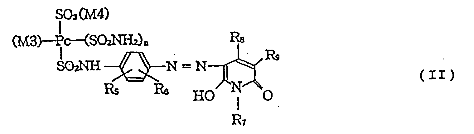
- the phthalocyanine dye of the general formula (II) can suitably be combined with the pyrazolone dye of the general formula (I) of the present invention without affecting influence on the aforementioned characteristics (a) to (e) of the color filter.
- Preferred dye which can be combined with the pyrazolone dye of the present invention is a phthalocyanine dye of the formula: wherein Pc is a phthalocyanine residue; M3 is Cu, Zn or Ni; M4 is an alkali metal such as Na, K and Li, or NH 4 ; R 5 and R 6 are each independently an SO 3 (M5) group, a substituted or unsubstituted amide group (for example, -NHCOCH 3 , -NHCOC 2 H 5 and -NHCOC 3 H 7 ), or a linear or branched alkyl group, for example, having 1 to 5 carbon atoms, M5 is an alkali metal such as Na, K and Li, or NH 4 ; R 7 and R 8 are each independently a linear or branched alkyl group, for example, having 1 to 5 carbon atoms; R 9 is -CONHR 10 , -COOH, or -COO(M6), where M6 is an alkali metal such as Na
- a weight ratio is preferably in the range of from about 1:4 to about 4:1 in consideration of ink ejection characteristics and color filter properties.
- the total amount of the dyes in the ink ranges preferably from 0.1 to 15 % by weight, more preferably from 1 to 10 % by weight, still more preferably from 2 to 8 % by weight to obtain desirable optical properties of the pixels and to keep the properties of the ink suitable for precise ejection by ink-jet recording.
- Aqueous media including water can be used for a medium constituting the ink, which keeps coloring matters in a dissolved state, a dispersed state or a dissolved and dispersed state.
- a content of water as a component in the aqueous medium ranges preferably from 10 to 90 % by weight, more preferably from 20 to 80 % by weight based on the total weight of the ink.
- the aqueous medium may contain a water-soluble organic solvent.
- a solubility of components in an ink can be improved, and a viscosity of the ink can be adjusted by the use of a water-soluble organic solvent shown below.
- a water-soluble organic solvent having a boiling point ranging from about 150°C to about 250°C is suitably used since a possibility of occurrence of clogging of orifices can be decreased in ejecting the ink to deposit it on a base plate by an ink-jet recording system and also an adhesiveness to the base plate is not lowered.
- Table 1 shows examples of the useful water-soluble organic solvent.
- the ink may contain a surfactant of a nonionic, anionic or cationic type.
- the ink may contain another additives such as a pH-controlling agent, a mildewproofing agent and the like, as needed.
- Such a type of ink is used suitable for formation of a green pixel in which the ink is ejected through a recording head by ink-jet system, such as of a bubble jet type employing an electrothermal transducer as the energy-generating element or of piezo jet type employing a piezo element, to deposit on a color filter base plate.
- An ink ejection property can be made excellent in particular when, at the time of ejection, the ink has a surface tension ranging from 30 to 68 dyn/cm and an ink viscosity not higher than 15 cP, preferably not higher than 10 cP, more preferably not higher than 5 cP, at 25°C. Specific ink compositions for achieving the desirable properties in this embodiment are shown later in Examples.
- Figs. 1A to 1E illustrate a process for producing a color filter of an embodiment of the present invention.
- Fig. 1A shows a base plate 1 on which a light-shielding portion 2 (hereinafter referred to as a "black matrix”) is formed in the form of a pattern.
- a black matrix 2 a light-shielding portion 2
- Reference numeral 7 denotes a portion where light can be passed through.
- a layer in which a curable resin composition is contained is formed on the base plate 1 having black matrix 2 formed thereon, thereby providing an ink-receiving layer 3 (Fig. 1B).
- the base plate employed is usually made of glass. However, any material other than glass may be used, so far as characteristics such as light transmittance and mechanical strength-required commonly for the liquid crystal color filter can be satisfied. For example, a transparent acrylic resin can be used as the base plate.
- An ink-receiving layer 3 may be formed from a conventional material.
- acrylic resins, epoxy resins and imide resins are suitable.
- a resin containing a water-soluble cellulosic polymer such as hydroxypropyl cellulose, hydroxyethyl cellulose, methyl cellulose, and carboxymethyl cellulose.
- polyvinylpyrrolidone, polyvinyl alcohol, polyvinylacetal, polyurethane, and polyesters and natural resins such as albumin, gelatin, casein, starch, cationic starch, gum arabic, and sodium alginate.
- mixtures of hydroxypropyl cellulose and a methylol-melamine resin or polymers containing a homopolymer having the structural unit (III): wherein R 11 is H or CH 3 , R 12 is H or a linear or branched alkyl group which may be substituted by an alkyl having 1 to 5 carbon atoms; and/or a copolymer thereof with another vinyl monomer.
- Examples of the monomer corresponding to the above structural unit (III) include specifically N-methylolacrylamide, N-methoxymethylacrylamide, N-ethoxymethylacrylamide, N-isopropoxymethylacrylamide, N-methylolmethacrylamide, N-methoxymethylmethacrylamide and N-ethoxymethylmethacrylamide.
- Examples of the another vinyl monomer include acrylic acid, methacrylic acid, acrylates such as methyl acrylate and ethyl acrylate; methacrylates such as methyl methacrylate, ethyl methacrylate; hydroxyl group-containing vinyl monomers such as hydroxymethyl methacrylate, hydroxyethyl methacrylate, hydroxymethyl acrylate and hydroxyethyl acrylate; styrene, ⁇ -methylstyrene, acrylamide, methacrylamide, acrylonitrile, allylamine, vinylamine, vinyl acetate, and vinyl propionate.
- the copolymerization molar ratio of the monomer corresponding to the general formula (III) to the another vinyl monomer ranges preferably from 95:5 to 5:95.
- the aforementioned ink-receiving layer 3 may contain additives, as needed.
- the additive include surfactants, dye-fixing agents (waterproofing agents), antifoaming agents, antioxidants, fluorescent whitening agents, UV absorbing agents, dispersants, viscosity-controlling agents, pH-controlling agents, mildew-proofing agents, and plasticizers.
- the additives may be selected arbitrarily from known compounds to meet the purpose.
- the ink-receiving layer 3 can be formed by any of coating methods such as spin coating, roll coating, bar coating, spray coating, dip coating and the like. The layer may be prebaked, if necessary.
- the aforementioned ink of the present invention is deposited on image formation portions by an ink-jet system to dye prescribed portions of the ink-receiving layer 3 (Fig. 1C).
- Reference numeral 4 denotes an ink-jet head comprising nozzles for R, G and B inks.
- the ink-jet system may be of a bubble jet type employing an electrothermal transducer as an energy-generating element, or of a piezo jet type employing a piezo element.
- the colored area and the colored pattern may be selected as desired.
- a preferable method for forming pixels by an ink-jet system is described below by reference to Fig. 2.
- Fig. 2 is a block diagram showing a constitution of an apparatus for forming colored portions of a color filter.
- a CPU 21 is connected through a head driving circuit 22 to an ink-jet head 4.
- the CPU 21 is so constituted that a control program information in a program memory 23 is introduced.
- the CPU 21 drives an ink-jet recording head 4 to a prescribed pixel-forming position (not shown in the drawing) on the base plate 1 to bring the prescribed pixel position below the ink-jet head 4.
- An ink 24 of a prescribed color is ejected onto the position to color it. This operation is conducted throughout the desired pixel positions on the base plate 1 to produce a color filter.
- any of conventional inks may be used for forming red and blue pixels.
- Pixels of R, G and B are respectively formed by dyeing prescribed portions of an ink-receiving layer 3, simultaneously or successively, using such conventional red and blue inks with the green ink of the present invention.
- the ink-receiving layer 3 is cured (Fig. 1D).
- the curing treatment may be conducted by a method suitable for a curable resin used in the ink-receiving layer.
- the ink-receiving layer is cured by heating or light irradiation or a combination of heating and light irradiation to form respective colored pixels 11.
- the light irradiation intensity ranges preferably from about 1 to about 3,000 mJ/cm 2 .
- the heat treatment can be conducted by means of an oven, a hot plate, or the like at a temperature ranging from 150°C to 250°C for a time ranging from 1 minute to 120 minutes.
- a protection layer 6 is formed on the cured ink-receiving layer 3 as necessary (Fig. 1E).
- the protection layer 6 can be formed by applying a resin material, which is curable by light irradiation or a heat treatment, and curing subsequently, or by vapor-depositing an inorganic film or sputtering.
- a resin material which is curable by light irradiation or a heat treatment, and curing subsequently, or by vapor-depositing an inorganic film or sputtering.
- the material of the protection layer there is suitably used materials which do not impair its transparency required for the color filter when they are made to a protection layer and are capable of withstanding the later process such as an ITO formation process or an orientation film formation process.
- the material include acrylic resins such as epoxy acrylates, urethane acrylates and the like as an organic material; and SiO 2 and the like as an inorganic material.
- the color filter 9 of Fig. 1E of this embodiment can be prepared.
- a second embodiment of the color filter of the present invention is described below. This embodiment is different from the first embodiment in the point that portions corresponding to a black matrix 2 on an ink-receiving layer 3 are cured prior to application of an ink to an ink-receiving layer 3 to lower the ink absorbency in advance. This embodiment is explained along with the steps in the production process by reference to Figs. 4A to 4F.
- a base plate 1 which has a black matrix 2 formed on the surface thereof, in the same manner as in the first embodiment (Fig. 4A).
- an ink-receiving layer 3 is formed so as to cover the black matrix 2 (Fig. 4B). It is preferable to use a material for the ink-receiving layer 3 which lowers its ink absorbency at the surface by light irradiation.
- the material for constituting the ink-receiving layer 3 in this embodiment there can be suitably used materials in which a photopolymerization initiator is additionally incorporated into the aforementioned materials for the ink-receiving layer 3 of the first embodiment.
- the photopolymerization initiator include onium salts and halogenated triazine compounds.
- the onium salts are specifically exemplified by triphenylsulfonium hexafluoroantimonate, triphenylsulfonium tetrafluoroborate, triphenylsulfonium hexafluorophosphate, triphenylsulfonium trifluoromethylsulfonate, and derivatives thereof; and diphenyliodonium hexafluoroantimonate, diphenyliodonium tetrafluoroborate, diphenyliodonium hexafluorophosphate, diphenyliodonium trifluoromethylsulfonate, and derivatives thereof.
- halogenated triazine compounds and derivatives thereof are preferred.
- the amount of the photopolymerization initiator to be incorporated in the ink-receiving layer material ranges from 0.01 to 20 % by weight, preferably from 0.1 to 10 % by weight.
- the portion corresponding to the black matrix 2 of the ink-receiving layer 3 is cured by selective exposure to light, for example, by use of a photo mask 41 (Fig. 4C).
- a portion having less ink-absorbency (portion not to be colored) 42 is formed selectively on the ink-receiving layer 3.
- the photo mask 41 for the light pattern exposure has openings 43 for selective light irradiation of the portions of the ink-receiving layer corresponding to the black matrix 2.
- the width (y) of the openings 43 is preferably smaller than the width (x) of the black matrix 2.
- the width of portion not to be colored of the ink-receiving layer 3 is preferably made smaller than the width (x) of the black matrix 2.
- the portions non to be colored can be formed by the use of the black photo mask 41 having the width (y) of the openings 43 smaller than the width (x) of the black matrix 2.
- the light of irradiation onto the ink-absorption layer for formation of non-colored portions 43 is not specially limited, but the intensity thereof is preferably in the range of from about 1 to about 3,000 mJ/cm 2 .
- the heat treatment can be conducted at a temperature ranging from 150°C to 250°C for 1 minute to 120 minutes by means of an oven, a hot plate or the like.
- Figs. 4D to 4F Subsequent steps are conducted by applying the ink onto portions where pixels are to be formed by means of an ink-jet method and curing the ink-receiving layer 3 in the same manner as shown in Figs. 1C to 1E, thereby producing a color filter
- the method of this Embodiment prevents troubles caused by color mixing and color irregularity at the border between pixels, in particular between adjacent pixels, in formation of R, G and B pixels by an ink-jet system, and enables production of high-quality color filters at a low production cost.
- a third embodiment of the present invention is described below along the production steps by reference to Figs. 5A to 5D.
- This embodiment has one feature in the point that the color filter is prepared without providing an ink-receiving layer 3.
- a base plate 1 which has a black matrix 2 formed on the surface thereof (Fig. 5A), in the same manner as in the first embodiment.
- walls of a prescribed thickness e.g., 0.5 ⁇ m or more
- a black resin resist is patterned to form a black matrix 2.
- the aforementioned green ink 52 of the present invention a conventional R ink 51 and a conventional B ink 53 are applied to fill light-transmissive portions 55 between the black matrices 2 by utilizing an ink-jet system.
- the inks are applied so as not to cause overlap of the different color inks on black matrix 2.
- the G ink for forming green pixels employed in this embodiment may be the aforementioned ink containing a pyrazolone dye.
- an G ink comprising a resin which is curable by energy application such as light irradiation or heating or a combination of light irradiation and heating.
- the R ink and the B ink also contain each preferably the above resin.
- the aforementioned resin there may be used commercially available various resins or hardeners. However, it is preferable to use the one which does not cause troubles such as solidification and the like before use.
- the resins include acrylic resins, epoxy resins and melamine resins.
- the component curable by light, heat or both light and heat is contained in the ink in an amount, for example, ranging from 0.1 to 20 % by weight based on the total weight of the ink.
- the inks applied to the openings 55 of Fig. 5A on the base plate 1 are partially cured by light irradiation, heating or both light irradiation and heating, as shown in Fig. 5C.
- a curable resin composition is applied so as to cover both the black matrix 2 and colored portions 54 formed by the color inks, as shown in Fig. 5D.
- the coated matter is subjected to light irradiation and/or heating treatment to cure the colored portions 54 to complete colored pixels 11 and to cure the curable resin composition to form simultaneously a protection layer 6, thereby obtaining a color filter 9.
- the protection layer 6 can be formed as above by curing a curable resin by light irradiation, heat treatment or a combination of light irradiation and heat treatment. Otherwise, the protection layer 6 may be formed from an inorganic film by vapor deposition or sputtering.
- the material of the protection film 6 is preferably transparent as a color filter, and is capable of withstanding the subsequent steps such as ITO formation, orientation film formation and the like.
- the color filter 9 formed in the respective embodiments above is used for constituting a liquid crystal panel.
- a color filter 9 and a base plate 61 are placed in opposition as shown in Fig. 6, and a liquid crystal composition 62 is charged therebetween to form a liquid crystal panel.
- Fig. 6 is a sectional view of a TFT color liquid crystal panel having a color filter of the present invention.
- a color liquid crystal panel is formed by putting together the color filter 9 and the base plate 61 in opposition and filling the liquid crystal composition 62 therebetween.
- a TFT not shown in the drawing
- transparent pixel electrodes 63 On the inside face of one of the base plates of the liquid crystal panel.
- a counter (common) electrode 64 is formed on the entire face of a protection layer 6 of the color filter 9.
- An orientation film 65 is formed on the inside face of the counter base plate 61 so as to cover the pixel electrodes 63.
- Another orientation film 66 is also formed on the inside face of the counter base plate 64.
- the orientation films after rubbing treatment can align the liquid crystal molecules in one direction.
- a polarizing plates 67 are bonded outside the color filter base plate 1 and the counter base plate 61.
- the liquid crystal panel conducts display by utilizing the liquid crystal as a light shutter for changing the transmittance of light 68 from a back light source which is generally a combination of a fluorescent lamp and a light-scattering plate.
- the black matrix 2 and the colored portions 11 are usually formed on the color filter base plate side as shown in Fig. 6.
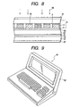
- the BM is formed on the TFT base plate side reverse to the BM as shown in Fig. 7.
- the CF is formed on the TFT base plate side in opposition to the BM as shown in Fig. 8.
- Reference numerals in Figs. 7 and 8 have the same meaning as in Fig. 6.
- Reference numeral 43 in Fig. 6 denotes a portion having less ink absorbency
- reference numerals 17 and 69 in Fig. 7 denotes a colored pixel and a black matrix, respectively.
- the liquid crystal panel prepared in such the process can be used as an image display device 92 of a computer 91 or the like as shown in Fig. 9.
- a glass base plate was provided which had a black matrix made of chromium having openings in a size ranging from 60 to 150 ⁇ m.
- a curable resin composition composed of a copolymer of N-methylolacrylamide and hydroxyethyl methacrylate in a ratio of 50:50 by weight was applied in a film thickness of 1.2 ⁇ m by spin coating, and prebaked at 120°C for 20 minutes to form an ink-receiving layer.
- G inks were prepared by using a combination of any one of pyrazolone dyes A1 to A8 shown in Table 2 and a phthalocyanine dye of the formula (IV) according to Formulation 1 for G Ink below.
- R Ink was prepared by using C.I. Direct Red 80 as the dye
- B Ink was prepared by using C.I. Acid Blue 83 as the dye according to Formulation 1 for R and B Inks. wherein Zn-Pc is a zinc-phthalocyanine residue.
- the G Ink comprising pyrazolone dye A1, the R Ink and the B Ink were applied to portions where pixels of the respective colors were to be formed by an ink-jet printer to color the matrix pattern in R, B and G.
- the colored matter was then subjected to a baking treatment at 230°C for 50 minutes to cure the applied inks.
- a two-pack type acrylic thermosetting resin material (SS-7625, trade name, produced by Japan Synthetic Rubber Co.) was applied thereto in a thickness of 1 ⁇ m by spin coating.
- the coated matter was heat treated at 240°C for 20 minutes to cure the resin.
- the color filter for a liquid crystal display device of Example 1 was prepared.
- color filters for a liquid crystal display device of Examples 2 to 8 were prepared respectively in the same manner as above except that G Ink was changed to G Inks comprising pyrazolone dyes A2 to A8, respectively.
- the color filters of Examples 1 to 8 for a liquid crystal display device were evaluated.
- the G Inks comprising one of pyrazolone dyes A1 to A8, respectively, were evaluated for an ink-jet ejection stability.
- the evaluation standards and the evaluation results are shown in Table 3.
- Ink Formulation 1 for G Ink Pyrazolone dye: 3 % by weight Phthalocyanine dye: 2.7 % by weight Ethylene glycol monobutyl ether (bp 170°C): 39 % by weight Ethyl alcohol (bp 78°C): 6 % by weight Water 49.3 % by weight Ink Formulation 1 for R and B Inks Dye: 5.7 % by weight Ethylene glycol monobutyl ether (bp 170°C): 39 % by weight Ethyl alcohol (bp 78°C): 6 % by weight Water 49.3 % by weight
- a liquid crystal panel was prepared with the above color filter.
- the transparency of the G pattern portions was evaluated visually on three evaluation grades:
- the color filter was left standing at 60°C for 48 hours.
- the degree of bleeding (increase of the color portion area) of the G pattern was evaluated.
- the color filter was subjected to a pressure cooker treatment under conditions of temperature of 125°C and humidity of 85% for 6 hours. After the treatment, the state of the G pattern portions was observed by microscopy. The adhesiveness of the G pattern portions was evaluated on three evaluation grades:
- G Ink was set to a printer, BJ-10 (trade name, a product of Canon Inc), and character pattern was printed on 300 paper sheets of A4 size. The 300th printed paper sheet was examined visually. The ejection stability of the G Ink was evaluated on three evaluation grades:
- the color filter was exposed to xenon light for 50 hours by means of Fade-o-Meter Model Ci35, (trade name, manufactured by Atlas Co.). Then the degree of discoloration of G pattern portions was calculated as ⁇ E (color difference) according to CIE. The light fastness of the R pattern portions was evaluated on three grades:
- Evaluation results are shown in Table 3.
- Example No. Evaluation item 1 2 3 4 5 1 A A A A A 2 A A A A 3 A A A A B 4 A A A A B 5 B A A A B 6 B A A A B 7 A A A A B 8 A A B A B
- a black matrix of 1.0 ⁇ m thick was formed by applying a photosensitive resin containing a black pigment (Black Pigment Resist CK-S171B, trade name, produced by Fuji Hunt K.K.) by spin coating, and subjecting the resin to pattern light exposure, development, and heat treatment.
- a photosensitive resin containing a black pigment Black Pigment Resist CK-S171B, trade name, produced by Fuji Hunt K.K.
- R Ink, G Ink and B Ink were respectively injected by an ink-jet printer.
- the inks were cured by heat treatment at 230°C for 30 minutes to form a color filter for a liquid crystal element.
- the compositions of the Inks were shown below as Ink Formulation 2 for G Ink, and Ink Formulation 2 for R and B Inks.
- Dye combinations respectively composed of a pyrazolone dye selected from the dyes A1 to A8 in Table 2, and the phthalocyanine dye of the structural formula (IV)
- Liquid crystal panels were prepared with the above color filters. The transparency of the G pattern portions was evaluated visually on three grades:
- the color filters were examined by microscopy.
- the uniformity of the G pattern portions was evaluated on three grades:
- the color filter was subjected to a pressure cooker treatment under the conditions of 125°C and 85% for 6 hours. After the treatment, the state of the G pattern portions was observed by microscopy. The adhesiveness of the G pattern portions was evaluated on three grades:
- the G Ink was set to a printer, BJ-10 (trade name, a product of Canon Inc), and character pattern was printed on 300 paper sheets of A4 size. The 300th printed paper sheet was examined visually. The ejection stability the G Ink was evaluated on three grades:
- the color filter was exposed to xenon light for 50 hours by means of Fade-o-Meter Model Ci35 (trade name, manufactured by Atlas Co.). Then the degree of discoloration was represented by ⁇ E (color difference) according to CIE. The light fastness of the G pattern portions was evaluated on three grades:
- Evaluation results are shown in Table 5.
- Example No. Evaluation item 1 2 3 4 5 9 A A A A A 10 A A A A 11 A A A A B 12 A A A A B 13 B A A B B 14 B A A B B 15 A A A A B 16 A A B A B
- G Inks were prepared with the pyrazolone dyes A1 to A8 of Table 2 according to Formulation 3 below.
- the G Ink was set to an ink-jet printer BJC-620 (trade name, manufactured by Canon Inc). Solid printing was conducted on an OHP film sheet (CF-102, trade name, produced by Canon Inc).
- Ink Formulation 3 Pyrazolone dye 5.0 % by weight Ethylene glycol (bp 197°C) 20.0 % by weight Ethyl alcohol (bp 78°C) 4.0 % by weight water 71.0 % by weight
- a printed image was projected by an OHP onto a screen. The projected image was examined visually. An ink which could form a projected image having a clear recorded area high in optical density arid in contrast was evaluated as a grade A. An ink which formed a projected image with a little lower optical density with some darkness was evaluated as a grade B. An ink which formed a projected image with significant darkness and a low optical density, without sharpness was evaluates as a grade C.
- bleeding means the phenomenon such that the adjacent deposited dots spread irregularly on the ink-receiving layer to form assemblage of dots to cause image density irregularity owing to a fluidity of the ink before complete fixation to the ink-receiving layer.
- a color panel can simply be produced with the ink containing the aforementioned dye by an ink-jet system.
- An ink comprising the dye of the present invention satisfies the requirements for the characteristics of transparency of the pixels, no bleeding, adhesiveness to the base plate, and high ejectability.
- the ink is useful for uses other than the color filter such as business printers, and industrial printers.
Landscapes
- Chemical & Material Sciences (AREA)
- Physics & Mathematics (AREA)
- Life Sciences & Earth Sciences (AREA)
- Engineering & Computer Science (AREA)
- Materials Engineering (AREA)
- Wood Science & Technology (AREA)
- Organic Chemistry (AREA)
- General Physics & Mathematics (AREA)
- Optics & Photonics (AREA)
- Optical Filters (AREA)
- Inks, Pencil-Leads, Or Crayons (AREA)
Claims (30)
- Tinte zum Tintenstrahlaufzeichnen, aufweisend einen Pyrazolonfarbstoff der allgemeinen Formel (I)wobei R1 durch CF3 gebildet ist und R2 ausgewählt ist aus der Gruppe bestehend aus einem Wasserstoffatom, einer OH-Gruppe, einem Halogenatom, einer linearen oder verzweigten Alkylgruppe mit 1 bis 5 Kohlenstoffatomen, einer Nitrogruppe, einer CF3-Gruppe oder einer SO3(M1)-Gruppe, in der M1 ein Alkalimetall oder NH4 ist; und sowohl R3 als auch R4 eine SO3(M2)-Gruppe ist, wobei M2 ein Alkalimetall oder NH4 ist.

- Tinte nach Anspruch 1, worin R2 ein Wasserstoffatom in dem Pyrazalonfarbstoff der allgemeinen Formel (I) ist.
- Tinte zum Tintenstrahlaufzeichnen aufweisend einen Pyrazalonfarbstoff der allgemeinen Formel (I) und einen Phthalocyaninfarbstoff:wobei R1 und R2 jeweils unabhängig voneinander ausgewählt sind aus der Gruppe bestehend aus einem Wasserstoffatom, einer OH-Gruppe, einem Halogenatom, einer linearen oder verzweigten Alkylgruppe mit 1 bis 5 Kohlenstoffatomen, einer Nitrogruppe, einer CF3-Gruppe oder einer SO3(M1)-Gruppe, wobei M1 ein Alkalimetall oder NH4 ist; und sowohl R3 als auch R4 eine SO3(M2)-Gruppe ist, wobei M2 ein Alkalimetall oder NH4 ist.

- Tinte nach Anspruch 3, worin der Phthalocyaninfarbstoff eine Struktur der allgemeinen Formel (II) aufweist:wobei Pc ein Phthalocyaninrest ist, M3 Cu, Zn oder Ni ist; R5 und R6 jeweils unabhängig voneinander eine SO3(M5)-Gruppe, eine substituierte oder nicht substituierte Amidgruppe, oder eine substituierte oder nicht substituierte Alkylgruppe ist; R7 und R8 jeweils unabhängig voneinander eine substituierte oder nicht substituierte Alkylgruppe sind; R9 -CONHR10, -COOH oder -COO(M6) ist; R10 ein Wasserstoffatom oder eine substituierte oder nicht substituierte Alkylgruppe ist; n eine natürliche Zahl mit dem Wert 0, 1 oder 2 ist; M4, M5 und M6 jeweils unabhängig voneinander ein Alkalimetall oder NH4 ist.

- Tinte nach einem der Ansprüche 1 bis 4, in der die Tinte die Farbstoffe in einer Gesamtkonzentration im Bereich von 0,1 bis 15 Gew.-% basierend auf dem totalen Gewicht der Tinte aufweist.
- Tinte nach einem der Ansprüche 1 bis 5, der die Tinte ein Lösungsmittel mit einem Siedepunkt im Bereich von 150°C bis 250°C bei einer Konzentration im Bereich von 5 bis 50 Gew.-% basierend auf dem Gesamtgewicht der Tinte aufweist.
- Tinte nach einem der Ansprüche 1 bis 6, in der die Tinte weiterhin ein härtbares Harz aufweist.
- Tinte nach Anspruch 7, in der das härtbare Harz zumindest durch Lichtbestrahlung und/oder Wärmebehandlung härtbar ist.
- Farbfilter aufweisend:wobei zumindest eines der gefärbten Pixel einen Pyrazalonfarbstoff der allgemeinen Formel (I) aufweist:eine lichtdurchlässige Basisplatte; undgefärbte Pixel an vorbestimmten Positionen auf der Basisplatte,wobei R1 CF3 ist und R2 ausgewählt ist aus der Gruppe bestehend aus einem Wasserstoffatom, einer OH-Gruppe, einem Halogenatom, einer linearen oder verzweigten Alkylgruppe mit 1 bis 5 Kohlenstoffatomen, einer Nitrogruppe, einer CF3-Gruppe oder einer SO3(M1)-Gruppe, wobei M1 ein Alkalimetall oder NH4 ist; und sowohl R3 als auch R4 eine SO3(M2)-Gruppe sind, wobei M2 ein Alkalimetall oder NH4 ist.

- Farbfilter nach Anspruch 9, in dem R2 ein Wasserstoffatom in dem Pyrazalonfarbstoff der allgemeinen Formel (I) ist.
- Farbfilter aufweisend:wobei R1 und R2 jeweils unabhängig voneinander ausgewählt sind aus der Gruppe bestehend aus einem Wasserstoffatom, einer OH-Gruppe, einem Halogenatom, einer linearen oder verzweigten Alkylgruppe mit 1 bis 5 Kohlenstoffatomen, einer Nitrogruppe, einer CF3-Gruppe oder einer SO3(M1)-Gruppe, wobei M1 ein Alkalimetall oder NH4 ist; und sowohl R3 als auch R4 eine SO3(M2)-Gruppe sind, wobei M2 ein Alkalimetall oder NH4 ist.eine lichtdurchlässige Basisplatte; undgefärbte Pixel an vorbestimmten Positionen auf der Basisplatte, wobeizumindest eines der gefärbten Pixel einen Pyrazalonfarbstoff derallgemeinen Formel (I) und einen Phthalocyaninfarbstoff aufweist:

- Farbfilter nach Anspruch 11, in dem der Phthalocyaninfarbstoff eine Struktur der allgemeinen Formel (II) aufweist:wobei Pc ein Phthalocyaninrest ist; M3 Cu, Zn oder Ni ist; R5 und R6 jeweils unabhängig voneinander eine SO3(M5)-Gruppe, eine substituierte oder nicht substituierte Amidgruppe, oder eine substituierte oder nicht substituierte Alkylgruppe ist; R7 und R8 jeweils unabhängig voneinander eine substituierte oder nicht substituierte Alkylgruppe ist; R9 -CONHR10, -COOH oder -COO(M6) ist; R10 ein Wasserstoffatom oder eine substituierte oder nicht substituierte Alkylgruppe ist, n eine natürliche Zahl mit dem Wert 0, 1 oder 2 ist; M4, M5 und M6 jeweils unabhängig voneinander ein Alkalimetall oder NH4 ist.
- Farbfilter nach einem der Ansprüche 9 bis 12, worin die Basisplatte eine Harzschicht auf ihrer Oberfläche aufweist und die Harzschicht die gefärbten Pixel bildet.
- Farbfilter nach einem der Ansprüche 9 bis 13, worin die gefärbten Pixel voneinander separiert sind, und eine lichtabschirmende Schicht zwischen entsprechenden gefärbten Pixel angeordnet ist.
- Farbfilter nach Anspruch 14, worin die lichtabschirmende Schicht eine nicht färbbare Oberfläche aufweist.
- Farbfilter nach einem der Ansprüche 9 bis 15, worin die gefärbten Pixel voneinander separiert sind; eine lichtabschirmende Schicht und eine Harzschicht, die die lichtabschirmende Schicht bedeckt, zwischen den gefärbten Pixeln angeordnet sind; und die Oberfläche der Harzschicht auf der lichtabschirmenden Schicht nicht färbbar ist.
- Flüssigkristalltafel aufweisend:einen Farbfilter nach einem der Ansprüche 9 bis 16,eine Tafelbasisplatte gegenüberstehend zu dem Farbfilter, undeine zwischen dem Farbfilter und der Tafelbasisplatte eingeschlossene Flüssigkristallzusammensetzung.
- Computer aufweisend eine Flüssigkristalltafel nach Anspruch 17 als Bildanzeigevorrichtung.
- Verfahren zum Erzeugen eines mit gefärbten Pixeln auf einer lichtdurchlässigen Basisplatte versehenen Farbfilters, aufweisend die Schritte:Ausstoßen einer Tinte nach einem der Ansprüche 1 bis 8 auf die lichtdurchlässige Basisplatte von einem Tintenstrahlsystem, um die Tinte an vorbestimmten Punkten abzulagern, wodurch zumindest eines der gefärbten Pixel dort gebildet wird.
- Verfahren zum Erzeugen eines Farbfilters nach Anspruch 19, wobei die lichtdurchlässige Basisplatte eine härtbare Harzschicht auf ihrer Oberfläche aufweist.
- Verfahren zum Erzeugen eines Farbfilters nach Anspruch 20, wobei das Material zum Bilden der Harzschicht ein Polymer mit einer wasserlöslichen Acryl-Monomereinheit aufweist.
- Verfahren zum Erzeugen eines Farbfilters nach Anspruch 20, wobei das Material zum Bilden der Harzschicht ein zellulosisches wasserlösliches Polymer aufweist.
- Verfahren zum Erzeugen eines Farbfilters nach einem der Ansprüche 20 bis 22, weiterhin aufweisend den Schritt:Aushärten der Harzschicht nachdem die Tinte auf der Harzschicht aufgebracht ist.
- Verfahren zum Erzeugen eines Farbfilters nach einem der Ansprüche 19 bis 23, wobei die lichtdurchlässige Basisplatte eine lichtabschirmende Schicht aufweist, um die gefärbten Pixel zu separieren.
- Verfahren zum Erzeugen eines Farbfilters nach Anspruch 24, wobei die Oberfläche der lichtabschirmenden Schicht nicht färbbar ist.
- Verfahren zum Erzeugen eines Farbfilters nach einem der Ansprüche 19 bis 25, wobei die lichtdurchlässige Basisplatte eine lichtabschirmende Schicht, die die auf der Oberfläche der Basisplatte ausgebildeten gefärbten Pixel voneinander separiert, und eine auf der lichtabschirmenden Schicht ausgebildete Harzschicht aufweist, wobei die Oberfläche der Harzschicht auf der lichtabschirmenden Schicht nicht färbbar ist.
- Verfahren zum Erzeugen eines Farbfilters nach einem der Ansprüche 24 bis 26, wobei eine färbbare Harzschicht zwischen den lichtabschirmenden Schichten ausgebildet ist.
- Verfahren zum Erzeugen eines mit gefärbten Pixeln auf einer lichtdurchlässigen Basisplatte ausgestatteten Farbfilters, aufweisend die Schritte:Ausstoßen einer Tinte nach einem der Ansprüche 7 oder 8 auf eine lichtdurchlässige Basisplatte von einem Tintenstrahlsystem, um die Tinte auf vorbestimmten Punkten auf der Oberfläche der Basisplatte aufzubringen, und Härten des in der Tinte enthaltenen härtbaren Harzes, um gefärbte Pixel zu bilden.
- Verfahren zum Erzeugen eines Farbfilters nach einem der Ansprüche 19 bis 28, wobei das Verfahren weiterhin die Schritte aufweist:Ausbilden einer härtbaren Harzschicht um die gefärbten Pixel zu bedecken, undHärten des härtbaren Harzes.
- Verfahren zum Erzeugen eines Farbfilters nach Anspruch 29, wobei das härtbare Harz durch die Zufuhr von Lichtenergie und/oder Wärmeenergie ausgehärtet wird.
Applications Claiming Priority (2)
| Application Number | Priority Date | Filing Date | Title |
|---|---|---|---|
| JP8622798 | 1998-03-31 | ||
| JP8622798 | 1998-03-31 |
Publications (2)
| Publication Number | Publication Date |
|---|---|
| EP0947859A1 EP0947859A1 (de) | 1999-10-06 |
| EP0947859B1 true EP0947859B1 (de) | 2003-06-11 |
Family
ID=13880914
Family Applications (1)
| Application Number | Title | Priority Date | Filing Date |
|---|---|---|---|
| EP99106587A Expired - Lifetime EP0947859B1 (de) | 1998-03-31 | 1999-03-31 | Tinte, Farbfilter, Flüssigkristallanzeige und Computer, sowie Verfahren zur Herstellung des Farbfilters |
Country Status (3)
| Country | Link |
|---|---|
| US (1) | US6248482B1 (de) |
| EP (1) | EP0947859B1 (de) |
| DE (1) | DE69908693D1 (de) |
Families Citing this family (25)
| Publication number | Priority date | Publication date | Assignee | Title |
|---|---|---|---|---|
| KR100789088B1 (ko) * | 1999-12-31 | 2007-12-26 | 엘지.필립스 엘시디 주식회사 | 칼라필터의 형성방법 |
| US6533852B2 (en) * | 2000-01-31 | 2003-03-18 | Canon Kabushiki Kaisha | Recording ink, method for ink jet recording, method for producing color filter, color filter, method for producing liquid crystal display panel, liquid crystal display panel, and yellow ink |
| JP2002098948A (ja) * | 2000-09-20 | 2002-04-05 | Hitachi Ltd | 液晶表示装置の製造方法 |
| TW200416261A (en) * | 2002-10-18 | 2004-09-01 | Nippon Kayaku Kk | Phthalocyanine compound for ink-jet printing, water-soluble green ink composition containing such compound and coloring substance using such composition |
| KR100961264B1 (ko) * | 2002-12-20 | 2010-06-03 | 엘지디스플레이 주식회사 | 콜레스테릭 액정 컬러필터를 포함하는 액정표시장치의제조방법 |
| BRPI0507723A (pt) * | 2004-03-16 | 2007-07-10 | Canon Kk | tinta para jato de tinta, método de gravação a jato de tinta, cartucho de tinta, e, aparelho de gravação a jato de tinta |
| JP4856885B2 (ja) * | 2004-03-16 | 2012-01-18 | キヤノン株式会社 | 液体組成物、液体組成物とインクのセット及び画像記録方法 |
| KR101117148B1 (ko) | 2004-04-02 | 2012-03-07 | 후지필름 가부시키가이샤 | 착색제함유 경화성 조성물, 컬러필터 및 그 제조방법 |
| CN1775533B (zh) * | 2004-11-19 | 2011-06-15 | 佳能株式会社 | 喷墨打印方法和喷墨打印装置 |
| US7654662B2 (en) * | 2004-11-19 | 2010-02-02 | Canon Kabushiki Kaisha | Ink jet printing method and ink jet printing apparatus |
| JP5020542B2 (ja) * | 2006-05-19 | 2012-09-05 | キヤノン株式会社 | 新規色素化合物及び該色素化合物を含有するインク |
| JP2008018711A (ja) * | 2006-06-14 | 2008-01-31 | Canon Inc | インクジェット記録装置、データ生成装置および記録物 |
| US8013051B2 (en) * | 2007-02-09 | 2011-09-06 | Canon Kabushiki Kaisha | Liquid composition, image forming method, cartridge, recording unit and ink jet recording apparatus |
| US7918928B2 (en) * | 2007-02-09 | 2011-04-05 | Canon Kabushiki Kaisha | Pigment ink, ink jet recording method, ink cartridge, recording unit and ink jet recording apparatus |
| JP5441354B2 (ja) * | 2007-05-23 | 2014-03-12 | キヤノン株式会社 | インクセット、インクジェット記録方法、インクカートリッジ及びインクジェット記録装置 |
| JP2009001004A (ja) * | 2007-05-23 | 2009-01-08 | Canon Inc | インクジェット記録装置、及びインクジェット記録方法 |
| JP5517515B2 (ja) * | 2008-08-08 | 2014-06-11 | キヤノン株式会社 | インクジェット記録方法、インクセット及びインクジェット記録装置 |
| JP5610722B2 (ja) * | 2008-08-08 | 2014-10-22 | キヤノン株式会社 | インクジェット用インク、インクジェット記録方法、インクカートリッジ、記録ユニット、及びインクジェット記録装置 |
| JP5995396B2 (ja) * | 2008-08-08 | 2016-09-21 | キヤノン株式会社 | インクセット、インクジェット記録方法、及びインクジェット記録装置 |
| JP5451556B2 (ja) * | 2009-09-18 | 2014-03-26 | キヤノン株式会社 | 色素化合物 |
| JP6602055B2 (ja) | 2014-06-30 | 2019-11-06 | キヤノン株式会社 | 自己分散顔料の製造方法、インクの製造方法、及びインクジェット記録方法 |
| US9789705B2 (en) | 2015-04-24 | 2017-10-17 | Canon Kabushiki Kaisha | Ink jet recording method |
| JP6759073B2 (ja) | 2015-12-28 | 2020-09-23 | キヤノン株式会社 | インク、インクカートリッジ、及びインクジェット記録方法 |
| JP6833475B2 (ja) | 2015-12-28 | 2021-02-24 | キヤノン株式会社 | インク、インクカートリッジ、及びインクジェット記録方法 |
| JP6759074B2 (ja) | 2015-12-28 | 2020-09-23 | キヤノン株式会社 | インク、インクカートリッジ、及びインクジェット記録方法 |
Family Cites Families (24)
| Publication number | Priority date | Publication date | Assignee | Title |
|---|---|---|---|---|
| JPS5767677A (en) * | 1980-10-15 | 1982-04-24 | Ricoh Co Ltd | Ink composition for ink jet recording |
| JPS5975205A (ja) | 1982-10-25 | 1984-04-27 | Seiko Epson Corp | カラ−フイルタの製造方法 |
| JPS6067576A (ja) | 1983-09-22 | 1985-04-17 | Ricoh Co Ltd | 水性インク |
| JPS60199077A (ja) * | 1984-03-22 | 1985-10-08 | Ricoh Co Ltd | インクジエツト用水性インク |
| US4804411A (en) | 1986-02-17 | 1989-02-14 | Canon Kabushiki Kaisha | Recording liquid |
| US4864324A (en) | 1986-08-13 | 1989-09-05 | Canon Kabushiki Kaisha | Color image forming method and ink used therefor |
| JPS63235901A (ja) | 1987-03-24 | 1988-09-30 | Fujitsu Ltd | カラ−フイルタの形成方法 |
| JP2597626B2 (ja) | 1988-02-26 | 1997-04-09 | 株式会社東芝 | カラーフィルター基板、カラーフィルター基板の製造方法およびカラーフィルター基板を用いた液晶表示装置 |
| US5135571A (en) | 1988-06-07 | 1992-08-04 | Canon Kabushiki Kaisha | Recording liquid |
| JPH02191683A (ja) | 1988-10-25 | 1990-07-27 | Canon Inc | 記録液及びこれを用いたインクジェット記録方法 |
| US5231417A (en) | 1989-02-02 | 1993-07-27 | Canon Kabushiki Kaisha | Ink jet recording process, device, apparatus and cartridge employing ink |
| US5216437A (en) | 1989-02-02 | 1993-06-01 | Canon Kabushiki Kaisha | Ink, and recording method making use of same |
| JP2663303B2 (ja) | 1989-02-02 | 1997-10-15 | キヤノン株式会社 | インク及び記録方法 |
| JPH0778191B2 (ja) | 1989-02-02 | 1995-08-23 | キヤノン株式会社 | インク及び記録方法 |
| US5135570A (en) | 1989-02-09 | 1992-08-04 | Canon Kabushiki Kaisha | Ink, and recording process making use of it |
| JP2942319B2 (ja) | 1989-09-19 | 1999-08-30 | キヤノン株式会社 | インク及びこれを用いたインクジェット記録方法 |
| JPH04123005A (ja) | 1990-09-14 | 1992-04-23 | Toray Ind Inc | カラーフィルタ製造法 |
| US5686585A (en) | 1993-02-02 | 1997-11-11 | Sumitomo Chemical Company, Limited | Azo dyes for use in color filters and method for production of color filters |
| JPH0821219A (ja) * | 1993-04-08 | 1996-01-23 | Osamu Nakada | 4サイクルエンジン、6サイクルエンジンに使用される、ロータリーバルブの駆動の方法。 |
| US5482546A (en) | 1994-03-30 | 1996-01-09 | Canon Kabushiki Kaisha | Dye, ink containing the same, and ink-jet recording method and instrument using the ink |
| JP3376169B2 (ja) | 1994-06-17 | 2003-02-10 | キヤノン株式会社 | カラーフィルタの製造方法及びその方法により製造されたカラーフィルタ |
| JP3372724B2 (ja) | 1994-09-21 | 2003-02-04 | キヤノン株式会社 | カラーフィルタおよびその製造方法、液晶パネルならびに情報処理装置 |
| JPH08211219A (ja) | 1995-02-02 | 1996-08-20 | Canon Inc | カラーフィルタ、その製造方法、カラーフィルタを備えた液晶パネル、及びカラーフィルタ用インク |
| JPH09291240A (ja) | 1996-04-26 | 1997-11-11 | Nippon Kayaku Co Ltd | カラーフィルタ用緑色インク組成物及びそれを用いるカラーフィルタの製造方法 |
-
1999
- 1999-03-25 US US09/276,514 patent/US6248482B1/en not_active Expired - Fee Related
- 1999-03-31 EP EP99106587A patent/EP0947859B1/de not_active Expired - Lifetime
- 1999-03-31 DE DE69908693T patent/DE69908693D1/de not_active Expired - Lifetime
Also Published As
| Publication number | Publication date |
|---|---|
| US6248482B1 (en) | 2001-06-19 |
| DE69908693D1 (de) | 2003-07-17 |
| EP0947859A1 (de) | 1999-10-06 |
Similar Documents
| Publication | Publication Date | Title |
|---|---|---|
| EP0947563B1 (de) | Tinte, Farbfilter, Flüssigkristallanzeige und Computer, sowie Verfahren zur Herstellung des Farbfilters | |
| EP0947859B1 (de) | Tinte, Farbfilter, Flüssigkristallanzeige und Computer, sowie Verfahren zur Herstellung des Farbfilters | |
| EP0703471B1 (de) | Farbfilter, Herstellungsverfahren desselben, und damit ausgestattete Flüssigkristallanzeigetafel | |
| US6533852B2 (en) | Recording ink, method for ink jet recording, method for producing color filter, color filter, method for producing liquid crystal display panel, liquid crystal display panel, and yellow ink | |
| JP3969884B2 (ja) | インク、カラーフィルター、液晶パネル、コンピュータ及びカラーフィルターの製造方法 | |
| JPH0829771A (ja) | カラーフィルタ、その製造方法、及びカラーフィルタを備えた液晶パネル | |
| JP2002265834A (ja) | 記録用インク、インクジェット記録方法、カラーフィルタの製造方法、カラーフィルタ及び液晶ディスプレイパネル | |
| US6063174A (en) | Ink for use in ink-jet recording, color filter, liquid crystal panel, computer and method for producing color filter | |
| JPH11302283A (ja) | フタロシアニン化合物、インク、カラーフィルタ、液晶パネル、コンピュータ及びカラーフィルタの製造方法 | |
| JPH0815522A (ja) | カラーフィルタ、その製造方法、及びカラーフィルタを備えた液晶パネル | |
| JPH08327811A (ja) | カラーフィルタ用インク、カラーフィルタ、カラーフィルタの製造方法および液晶パネル | |
| JP2000147241A (ja) | カラ―フィルタの製造方法、この製造方法で製造されたカラ―フィルタを用いた液晶素子及びインクジェットヘッド | |
| JP2001288393A (ja) | 記録用インク、インクジェット記録方法、カラーフィルタの製造方法、カラーフィルタ、液晶ディスプレイパネルの製造方法、液晶ディスプレイパネル、及び黄色インク | |
| JPH08327998A (ja) | カラーフィルタ用インク、カラーフィルタ、カラーフィルタの製造方法および液晶パネル | |
| JP2000089020A (ja) | カラーフィルタとその製造方法、該カラーフィルタを用いた液晶素子 | |
| JP3969885B2 (ja) | インク、カラーフィルタ、液晶パネル、コンピュータ及びカラーフィルタの製造方法 | |
| JPH08230314A (ja) | カラーフィルタの製造方法、カラーフィルタ及びこれを用いた液晶パネル | |
| JP2002212471A (ja) | インク、カラーフィルターとその製造方法、液晶パネル、コンピュータ及び画像表示デバイス | |
| JPH0829777A (ja) | カラーフィルタ、その製造方法、及びカラーフィルタを備えた液晶パネル | |
| JP2002302626A (ja) | 記録用インク、インクジェット記録方法、カラーフィルタの製造方法、液晶ディスプレイパネルの製造方法及び液晶ディスプレイパネル | |
| JPH0894821A (ja) | カラーフィルタ、その製造方法、及びカラーフィルタを備えた液晶パネル | |
| JP2002212469A (ja) | インク、カラーフィルタとその製造方法、液晶パネル、コンピュータ及び画像表示デバイス | |
| JPH10148708A (ja) | カラーフィルタ及びその製造方法、カラーフィルタ基板、液晶素子 | |
| JPH08211219A (ja) | カラーフィルタ、その製造方法、カラーフィルタを備えた液晶パネル、及びカラーフィルタ用インク | |
| JP2001214096A (ja) | 記録用インク、インクジェット記録方法、カラーフィルタの製造方法、被膜性インク、液晶ディスプレイパネルの製造方法、及び、液晶ディスプレイパネル |
Legal Events
| Date | Code | Title | Description |
|---|---|---|---|
| PUAI | Public reference made under article 153(3) epc to a published international application that has entered the european phase |
Free format text: ORIGINAL CODE: 0009012 |
|
| AK | Designated contracting states |
Kind code of ref document: A1 Designated state(s): DE FR GB IT |
|
| AX | Request for extension of the european patent |
Free format text: AL;LT;LV;MK;RO;SI |
|
| 17P | Request for examination filed |
Effective date: 20000405 |
|
| AKX | Designation fees paid |
Free format text: DE FR GB IT |
|
| 17Q | First examination report despatched |
Effective date: 20000818 |
|
| GRAG | Despatch of communication of intention to grant |
Free format text: ORIGINAL CODE: EPIDOS AGRA |
|
| GRAG | Despatch of communication of intention to grant |
Free format text: ORIGINAL CODE: EPIDOS AGRA |
|
| GRAH | Despatch of communication of intention to grant a patent |
Free format text: ORIGINAL CODE: EPIDOS IGRA |
|
| GRAH | Despatch of communication of intention to grant a patent |
Free format text: ORIGINAL CODE: EPIDOS IGRA |
|
| GRAA | (expected) grant |
Free format text: ORIGINAL CODE: 0009210 |
|
| AK | Designated contracting states |
Designated state(s): DE FR GB IT |
|
| PG25 | Lapsed in a contracting state [announced via postgrant information from national office to epo] |
Ref country code: IT Free format text: LAPSE BECAUSE OF FAILURE TO SUBMIT A TRANSLATION OF THE DESCRIPTION OR TO PAY THE FEE WITHIN THE PRESCRIBED TIME-LIMIT;WARNING: LAPSES OF ITALIAN PATENTS WITH EFFECTIVE DATE BEFORE 2007 MAY HAVE OCCURRED AT ANY TIME BEFORE 2007. THE CORRECT EFFECTIVE DATE MAY BE DIFFERENT FROM THE ONE RECORDED. Effective date: 20030611 Ref country code: FR Free format text: LAPSE BECAUSE OF FAILURE TO SUBMIT A TRANSLATION OF THE DESCRIPTION OR TO PAY THE FEE WITHIN THE PRESCRIBED TIME-LIMIT Effective date: 20030611 |
|
| REG | Reference to a national code |
Ref country code: GB Ref legal event code: FG4D |
|
| REF | Corresponds to: |
Ref document number: 69908693 Country of ref document: DE Date of ref document: 20030717 Kind code of ref document: P |
|
| PG25 | Lapsed in a contracting state [announced via postgrant information from national office to epo] |
Ref country code: DE Free format text: LAPSE BECAUSE OF FAILURE TO SUBMIT A TRANSLATION OF THE DESCRIPTION OR TO PAY THE FEE WITHIN THE PRESCRIBED TIME-LIMIT Effective date: 20030912 |
|
| PLBE | No opposition filed within time limit |
Free format text: ORIGINAL CODE: 0009261 |
|
| STAA | Information on the status of an ep patent application or granted ep patent |
Free format text: STATUS: NO OPPOSITION FILED WITHIN TIME LIMIT |
|
| 26N | No opposition filed |
Effective date: 20040312 |
|
| EN | Fr: translation not filed | ||
| PGFP | Annual fee paid to national office [announced via postgrant information from national office to epo] |
Ref country code: GB Payment date: 20080326 Year of fee payment: 10 |
|
| GBPC | Gb: european patent ceased through non-payment of renewal fee |
Effective date: 20090331 |
|
| PG25 | Lapsed in a contracting state [announced via postgrant information from national office to epo] |
Ref country code: GB Free format text: LAPSE BECAUSE OF NON-PAYMENT OF DUE FEES Effective date: 20090331 |