EP0947904A2 - Alimentation en courant alternatif utilisant la lumière du soleil - Google Patents
Alimentation en courant alternatif utilisant la lumière du soleil Download PDFInfo
- Publication number
- EP0947904A2 EP0947904A2 EP99300229A EP99300229A EP0947904A2 EP 0947904 A2 EP0947904 A2 EP 0947904A2 EP 99300229 A EP99300229 A EP 99300229A EP 99300229 A EP99300229 A EP 99300229A EP 0947904 A2 EP0947904 A2 EP 0947904A2
- Authority
- EP
- European Patent Office
- Prior art keywords
- power
- voltage
- target voltage
- boosting
- commercial power
- Prior art date
- Legal status (The legal status is an assumption and is not a legal conclusion. Google has not performed a legal analysis and makes no representation as to the accuracy of the status listed.)
- Granted
Links
Images




Classifications
-
- H—ELECTRICITY
- H02—GENERATION; CONVERSION OR DISTRIBUTION OF ELECTRIC POWER
- H02J—ELECTRIC POWER NETWORKS; CIRCUIT ARRANGEMENTS OR SYSTEMS FOR SUPPLYING OR DISTRIBUTING ELECTRIC POWER; SYSTEMS FOR STORING ELECTRIC ENERGY
- H02J3/00—Circuit arrangements for AC mains or AC distribution networks
- H02J3/38—Arrangements for feeding a single network from two or more generators or sources in parallel; Arrangements for feeding already energised networks from additional generators or sources in parallel
- H02J3/381—Dispersed generators
-
- G—PHYSICS
- G05—CONTROLLING; REGULATING
- G05F—SYSTEMS FOR REGULATING ELECTRIC OR MAGNETIC VARIABLES
- G05F1/00—Automatic systems in which deviations of an electric quantity from one or more predetermined values are detected at the output of the system and fed back to a device within the system to restore the detected quantity to its predetermined value or values, i.e. retroactive systems
- G05F1/66—Regulating electric power
- G05F1/67—Regulating electric power to the maximum power available from a generator, e.g. from solar cell
-
- H—ELECTRICITY
- H02—GENERATION; CONVERSION OR DISTRIBUTION OF ELECTRIC POWER
- H02S—GENERATION OF ELECTRIC POWER BY CONVERSION OF INFRARED RADIATION, VISIBLE LIGHT OR ULTRAVIOLET LIGHT, e.g. USING PHOTOVOLTAIC [PV] MODULES
- H02S40/00—Components or accessories in combination with PV modules, not provided for in groups H02S10/00 - H02S30/00
- H02S40/30—Electrical components
- H02S40/32—Electrical components comprising DC/AC inverter means associated with the PV module itself, e.g. AC modules
-
- H—ELECTRICITY
- H02—GENERATION; CONVERSION OR DISTRIBUTION OF ELECTRIC POWER
- H02J—ELECTRIC POWER NETWORKS; CIRCUIT ARRANGEMENTS OR SYSTEMS FOR SUPPLYING OR DISTRIBUTING ELECTRIC POWER; SYSTEMS FOR STORING ELECTRIC ENERGY
- H02J2101/00—Supply or distribution of decentralised, dispersed or local electric power generation
- H02J2101/20—Dispersed power generation using renewable energy sources
- H02J2101/22—Solar energy
- H02J2101/24—Photovoltaics
- H02J2101/25—Photovoltaics involving maximum power point tracking control for photovoltaic sources
-
- Y—GENERAL TAGGING OF NEW TECHNOLOGICAL DEVELOPMENTS; GENERAL TAGGING OF CROSS-SECTIONAL TECHNOLOGIES SPANNING OVER SEVERAL SECTIONS OF THE IPC; TECHNICAL SUBJECTS COVERED BY FORMER USPC CROSS-REFERENCE ART COLLECTIONS [XRACs] AND DIGESTS
- Y02—TECHNOLOGIES OR APPLICATIONS FOR MITIGATION OR ADAPTATION AGAINST CLIMATE CHANGE
- Y02E—REDUCTION OF GREENHOUSE GAS [GHG] EMISSIONS, RELATED TO ENERGY GENERATION, TRANSMISSION OR DISTRIBUTION
- Y02E10/00—Energy generation through renewable energy sources
- Y02E10/50—Photovoltaic [PV] energy
- Y02E10/56—Power conversion systems, e.g. maximum power point trackers
Definitions
- the present invention relates to an apparatus for supplying AC power to the commercial power line by using sunlight. More particularly, the invention relates to an apparatus for supplying AC power to the commercial power line by using sunlight wherein the output power of a solar battery is boosted and then converted into AC power.
- Some conventional apparatuses for supplying AC power to the commercial power line by using sunlight adapted to this kind of system for interconnection boost the voltage of DC power outputted from a solar battery by a booster circuit such as a boosting chopper circuit, and then convert the boosted DC power into AC power with an inverter circuit.
- the booster circuit is controlled in such a way that the voltage after boosting is a fixed value.
- the output voltage-output current characteristic of the solar battery is represented by a curve as shown in Fig. 6. Therefore, as the boosting rate of the booster circuit increases, the operating voltage of the solar battery shifts in the lowering directing ( to the left in Fig. 6), resulting in the unstable operating voltage of the solar battery.
- the present invention may provide an apparatus for generating electric power by using sunlight which operates to an optimum level.
- an apparatus for supplying AC power to the commercial power line by using sunlight comprising a solar battery for generating DC power boosting means for boosting the voltage of the DC power to the set target voltage power conversion means for converting the DC power set target voltage by said boosting means into AC power controlled predetermined frequency and adding it to commercial power line and control means for setting the target voltage of said boosting means based on the AC power from the commercial power line added said power conversion means, wherein the voltage of the AC power outputted from said power conversion means is higher than the voltage of the AC power from the commercial power line.
- boosting means boosts the voltage of DC power outputted from a solar battery to the set target voltage
- power conversion means converts the DC power set target voltage by the above boosting means into AC power controlled predetermined frequency and adding it to the commercial power line.
- the target voltage of the above boosting means is set by the control means based on the AC power outputted from the power conversion means.
- the boosting rate of the boosting means can be prevented from increasing more than necessary. Therefore, not only can the apparatus for supplying AC power to the commercial power line by using sunlight always operate with stability, but lowering of the conversion efficiency of the apparatus can be prevented without the need for setting the output voltage of the boosting means higher than necessary.
- an apparatus for supplying AC power to the commercial power line by using sunlight as claimed in claim 1, wherein said control means sets the target voltage of said boosting means in such a way that the target voltage is increased in accordance with the increase of the voltage of AC power from the commercial power line.
- the target voltage of the boosting means is set by the control means of the apparatus for supplying AC power to the commercial power line by using sunlight of the first aspect of the present invention in such a way that the target voltage is increased in accordance with the increase of the AC power outputted from said power conversion means.
- the boosting rate of the boosting means can be prevented from becoming higher than necessary.
- an apparatus for supplying AC power to the commercial power line sunlight comprising a solar battery for generating DC power boosting means for boosting the voltage of the DC power to the set target voltage power conversion means for converting the DC power set target voltage by said boosting means unto AC power controlled predetermined frequency and adding it to the commercial power line and control means for setting the target voltage of said boosting means on the AC power from the commercial power line added conversion means, wherein the voltage of the AC power outputted from said power conversion means is higher than the volume of the commercial power.
- an apparatus for supplying AC power to the commercial power line by using sunlight as claimed in claim 11, wherein said control means sets the target voltage of said boosting means in such a way that the target voltage is increased in accordance with the increase of the volume of the commercial power.
- Fig. 1 is a block diagram illustrating the schematic structure of an apparatus for supplying AC power to the commercial power line by using sunlight according to the present embodiment.
- Fig. 2 is a block diagram illustrating in detail the structure of a booster circuit according to the present embodiment.
- Fig. 3 is a timing chart used for describing the principle of operation of a booster circuit as well as illustrating the status of switching signals inputted to the booster circuit according to the present embodiment.
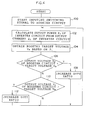
- Fig. 4 is a flow chart illustrating the sequence of a control program conducted when a booster circuit is controlled by a microcomputer according to the present embodiment.
- Fig. 5A is a graph illustrating one example of the relationship between the output power of an inverter circuit and the target voltage of a booster circuit according to the present embodiment.
- Fig. 5B is a graph illustrating another example of the relationship between the output power of an inverter circuit and the target voltage of a booster circuit.
- Fig. 5C is a graph illustrating a further example of the relationship between the output power of an inverter circuit and the target voltage of a booster circuit.
- Fig. 6 is a characteristic view of the output voltage-output current of a solar battery used for describing the problems of the conventional technique.
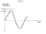
- Fig. 7 is a timing chart of the boosted voltage of the conventional apparatus.
- Fig. 1 is a block diagram illustrating the structure of an apparatus for supplying AC power to the commercial power line by using sunlight according to the present invention when applied as a system for interconnection connected to a commercial power system.
- a solar battery 12 is provided for an apparatus for supplying AC power to the commercial power line by using sunlight 10 according to the present embodiment, and the output terminal of the solar battery 12 is connected to a direct current noise filter 16 via a diode 14 for preventing reverse current.
- the output terminal of the noise filter 16 is connected to a booster circuit 18 for boosting inputted DC power based on a switching signal S inputted from a microcomputer 32, which will be described later.
- the output terminal of the booster circuit 18 is connected to an inverter circuit 20 for converting the inputted DC power into AC power controlled predetermined frequency and adding it to the commercial power line, and the output terminal of the inverter circuit 20 is further connected to an alternating current noise filter 22.
- the inverter circuit 20 serves for converting the inputted DC power into AC power (the output of this inverter circuit 20 is in, for example, a sawtooth waveform) whose frequency is the same as that of commercial power (for example, 50Hz or 60Hz) on the basis of the switching signal inputted from the microcomputer 32.
- the structure of the booster circuit 18 will be described in detail later.
- the output terminal of the noise filter 22 is connected to a commercial power system 28 via a parallel off conductor 24.
- the apparatus for supplying AC power to the commercial power line by using sunlight 10 is equipped with a microcomputer 32 for controlling the whole apparatus for supplying AC power to the commercial power line by using sunlight 10.
- the following are inputted to the microcomputer 32 at a predetermined sampling cycle (0.5 seconds in the present embodiment): the output voltage of the solar battery 12 detected at a first voltage detection portion 34 consisting of an isolation amplifier; the output current of the solar battery 12 detected at a first current detection portion 36 consisting of a current transformer CT; the output voltage of the booster circuit 18 detected at a second voltage detection portion 38 consisting of an isolation amplifier; the output current of the inverter circuit 20 detected at a second current detection portion 40 consisting of a current transformer CT; and the voltage waveform of the commercial power system 28 detected at a voltage waveform detection portion 42 consisting of a potential transformer PT.
- the microcomputer 32 is further connected to the parallel off conductor 24 so as to separate the inverter circuit 20 from the commercial power system 28 (parallel off) by opening a contact of the parallel off conductor 24 when the power outage of the commercial power system is detected.
- the microcomputer 32 is also connected to the booster circuit 18 so as to control the duty ratio of a switching signal S inputted to the booster circuit 18 based on the output voltage of the booster circuit 18 detected at the second voltage detection portion 38 and the output current of the inverter circuit 20 detected at the second current detection portion 40.
- the microcomputer 32 is connected to the inverter circuit 20 so as to generate and input to the inverter circuit 20 the switching signal, based on the voltage waveform of the commercial power system 28 detected at the voltage waveform detection portion 42, in such a way that the phase and frequency of the output power of the inverter circuit 20 match those of commercial power.
- booster circuit 18 corresponds to the boosting means of the present invention, the inverter circuit 20 to the power conversion means of the present invention, and the microcomputer 32 to the control means of the present invention, respectively.
- the booster circuit 18 is provided with a smoothing capacitor 50 and a choking coil 52 for smoothing the DC power inputted from the noise filter 16, a switching circuit 54 composed of a switching element and a diode, and a diode 56 and a capacitor 58 connected so as to obtain a filter effect on the output side.
- the booster circuit 18 comprises a boosting chopper circuit for boosting the output voltage Vs over the voltage VD applied from the noise filter 16, by utilizing the electromagnetic energy in the choking coil 52.
- a switching element comprising the above switching circuit 54, a power transistor, a power FET, etc. can be applied.
- Fig. 4 is a flow chart of a control program conducted by the microcomputer 32 so as to control the booster circuit 18.
- step 100 the input of the switching signal S, whose duty ratio to the booster circuit 18 is 0, begins. Subsequently, the output voltage of the booster circuit 18 is increased by increasing gradually the duty ratio of the switching signal S. When said output voltage reaches the predetermined target voltage, the operation of the inverter circuit 20 begins, and then the process moves to step 102.
- the predetermined target voltage at this point corresponds to the target voltage at the point that the output voltage P 1 of the inverter circuit 20 in the graph of Fig. 5A is 0.
- the target voltage V M after boosting by the booster circuit 18 is obtained based on the output power P 1 .
- the target voltage V M is obtained in such a way that the relation between the output power P 1 of the inverter circuit 20 and the target voltage V M is as shown in Fig. 5A.
- the target voltage V M is a fixed value when the output power P 1 of the inverter circuit 20 is from 0 through 1 [kW], and is increased in accordance with the increase of the output power P 1 when the output power P 1 is higher than 1 [kW].
- the target voltage V M at this point can be specifically obtained by applying a method of storing in advance in an unillustrated memory of the microcomputer 32 a table of the output power P 1 of the inverter circuit 20 and the target voltage V M of the booster circuit 18 which establish a relation shown in Fig. 5A, and referring to the table, etc.
- the above value, 1 [kW] is merely one example, and the present invention is not limited to this value.
- step 106 a determination is made as to whether the output voltage V S of the booster circuit 18 detected at the second voltage detection portion 38 is lower than the target voltage V M or not. If the output voltage V S is lower, the process moves to step 108, where the duty ratio of the switching signal S, which is being inputted to the boosting circuit 18, is increased in such a way that the output voltage V S of the booster circuit 18 is the target voltage V M . Then, the process returns to step 102.
- step 106 if it is determined that the output voltage V S of the booster circuit 18 is not lower than the target voltage V M , the process moves to step 110 where the determination is made as to whether the output voltage V S is higher than the target voltage V M or not. If the output voltage V S is higher, the process moves to step 112 where the duty ratio of the switching signal S is decreased in such a way that the output voltage V S of the booster circuit 18 is the target voltage V M . Then, the process returns to step 102.
- step 110 if it is determined that the output voltage V S of the booster circuit 18 is not higher than the target voltage V M , that is, if the output voltage V S is equal to the target voltage V M , the process returns to step 102 without changing the duty ratio of the switching signal S.
- the booster circuit 18 is controlled in such a way that the output voltage V S establishes the relationship shown in Fig. 5A in accordance with the value of the output power P 1 of the inverter circuit 20.
- the apparatus for supplying AC power to the commercial power line by using sunlight 10 As the output voltage V s of the booster circuit 18 is changed in accordance with the value of the output power P 1 of the inverter circuit 20, the boosting rate of the boosting circuit 18 does not become higher than necessary. Therefore, not only can the apparatus for supplying AC power to the commercial power line by using sunlight 10 always operate with stability, but the conversion efficiency of the apparatus is not lowered without the need for setting the output voltage V s of the booster circuit 18 higher than necessary.
- the boosted voltage is controlled by the output of the system voltage and the power conditioner.
- the boosting efficiency of the boosting means is lessened as the boosting ratio is increased. Thus, the small boosting ratio is generally preferred.
- the output voltage of the conversion means must be higher than the system voltage by + ⁇ or more. Otherwise, the efficiency of superimposition is decreased. Further, as the changes of boosted voltages vary depending on the system voltage and the loads as A and B shown in Fig. 7, the target voltage is inevitably set higher, allowing for these variations. Thus, it is conventionally conditioned that the boosting ratio is set higher than required.
- the present invention prevents unnecessary boosting by controlling the output of the converter in such a way that it is constantly + ⁇ (V). Further, as the system voltage varies depending on the output amount from the converter, the target voltage may be changed in accordance with the output amount.
- the output voltage V S of the booster circuit 18 is obtained in such a way that the output voltage V S establishes the relationship shown in Fig. 5A in accordance with the output power P 1 of the inverter circuit 20.
- the present invention is not limited to the same.
- the output voltage V S may be increased rectilinearly in accordance with the increase of the output power P 1 of the inverter circuit 20, or as shown in Fig. 5C, the output voltage V S may be increased stepwisely in accordance with the increase of the output power P 1 of the inverter circuit 20.
- a boosting chopper circuit (a direct-type booster circuit) is applied as the booster circuit 18.
- the present invention is not limited to the same.
- a booster circuit using a voltage doubler rectifier circuit, a serial-parallel chopper circuit, or the like may be applied.
- an apparatus for supplying AC power to the commercial power line by using sunlight of the first aspect of the present invention as the target voltage of the boosting means is set based on the AC power outputted from the power conversion means, an effect is obtained that the boosting rate of the boosting means can be prevented from becoming larger than necessary. Therefore, not only can the apparatus for supplying AC power to the commercial power line by using sunlight always operate with stability, but the lowering of conversion efficiency of the apparatus can be prevented without the need for setting the output voltage of the boosting means higher than necessary.
- the target voltage of the boosting means is set in such a way that the target voltage is increased in accordance with the increase of the voltage of AC power from the commercial power line, an effect is obtained that the boosting rate of the boosting means can be prevented from becoming higher than necessary.
Landscapes
- Engineering & Computer Science (AREA)
- Power Engineering (AREA)
- Electromagnetism (AREA)
- Sustainable Energy (AREA)
- Sustainable Development (AREA)
- Physics & Mathematics (AREA)
- Life Sciences & Earth Sciences (AREA)
- General Physics & Mathematics (AREA)
- Radar, Positioning & Navigation (AREA)
- Automation & Control Theory (AREA)
- Inverter Devices (AREA)
- Control Of Electrical Variables (AREA)
- Dc-Dc Converters (AREA)
- Charge And Discharge Circuits For Batteries Or The Like (AREA)
- Supply And Distribution Of Alternating Current (AREA)
Applications Claiming Priority (2)
| Application Number | Priority Date | Filing Date | Title |
|---|---|---|---|
| JP8468198 | 1998-03-30 | ||
| JP08468198A JP3744679B2 (ja) | 1998-03-30 | 1998-03-30 | 太陽光発電装置 |
Publications (3)
| Publication Number | Publication Date |
|---|---|
| EP0947904A2 true EP0947904A2 (fr) | 1999-10-06 |
| EP0947904A3 EP0947904A3 (fr) | 2000-08-02 |
| EP0947904B1 EP0947904B1 (fr) | 2003-10-29 |
Family
ID=13837445
Family Applications (1)
| Application Number | Title | Priority Date | Filing Date |
|---|---|---|---|
| EP99300229A Expired - Lifetime EP0947904B1 (fr) | 1998-03-30 | 1999-01-14 | Alimentation en courant alternatif utilisant la lumière du soleil |
Country Status (6)
| Country | Link |
|---|---|
| US (1) | US6058035A (fr) |
| EP (1) | EP0947904B1 (fr) |
| JP (1) | JP3744679B2 (fr) |
| KR (1) | KR100614570B1 (fr) |
| CN (1) | CN1122905C (fr) |
| DE (1) | DE69912342T2 (fr) |
Cited By (38)
| Publication number | Priority date | Publication date | Assignee | Title |
|---|---|---|---|---|
| EP1457857A3 (fr) * | 2003-03-11 | 2004-12-01 | Omron Corporation | Apparat de contrôle pour l'asservissement de puissance maximale. |
| WO2006111428A1 (fr) * | 2005-04-21 | 2006-10-26 | SIEMENS AKTIENGESELLSCHAFT öSTERREICH | Procede pour faire fonctionner un onduleur de courant comprenant un elevateur connecte en amont |
| WO2009101013A3 (fr) * | 2008-02-12 | 2009-10-08 | Eurotech Spa | Dispositif de conversion et d'accumulation d'énergie et procédé associé |
| US7839025B2 (en) | 2006-11-27 | 2010-11-23 | Xslent Energy Technologies, Llc | Power extractor detecting a power change |
| US7960870B2 (en) | 2006-11-27 | 2011-06-14 | Xslent Energy Technologies, Llc | Power extractor for impedance matching |
| US8013474B2 (en) | 2006-11-27 | 2011-09-06 | Xslent Energy Technologies, Llc | System and apparatuses with multiple power extractors coupled to different power sources |
| EP2290784A3 (fr) * | 2009-07-02 | 2012-12-19 | STMicroelectronics Srl | Circuit MPPT analogique pour une installation photovoltaique de puissance |
| EP2482419A4 (fr) * | 2010-02-09 | 2014-03-05 | Panasonic Corp | Dispositif de conversion électrique et système de pile à combustible le comportant |
| EP2710723A4 (fr) * | 2011-05-18 | 2015-10-28 | Gen Electric | Système de génération électrique, système de conversion électrique et procédé de fonctionnement d'un système de conversion électrique |
| US9431828B2 (en) | 2006-11-27 | 2016-08-30 | Xslent Energy Technologies | Multi-source, multi-load systems with a power extractor |
| US10910834B2 (en) | 2003-05-28 | 2021-02-02 | Solaredge Technologies Ltd. | Power converter for a solar panel |
| US11569660B2 (en) | 2006-12-06 | 2023-01-31 | Solaredge Technologies Ltd. | Distributed power harvesting systems using DC power sources |
| US11569659B2 (en) | 2006-12-06 | 2023-01-31 | Solaredge Technologies Ltd. | Distributed power harvesting systems using DC power sources |
| US11579235B2 (en) | 2006-12-06 | 2023-02-14 | Solaredge Technologies Ltd. | Safety mechanisms, wake up and shutdown methods in distributed power installations |
| US11598652B2 (en) | 2006-12-06 | 2023-03-07 | Solaredge Technologies Ltd. | Monitoring of distributed power harvesting systems using DC power sources |
| US11620885B2 (en) | 2012-01-30 | 2023-04-04 | Solaredge Technologies Ltd. | Photovoltaic panel circuitry |
| US11682918B2 (en) | 2006-12-06 | 2023-06-20 | Solaredge Technologies Ltd. | Battery power delivery module |
| US11687112B2 (en) | 2006-12-06 | 2023-06-27 | Solaredge Technologies Ltd. | Distributed power harvesting systems using DC power sources |
| US11728768B2 (en) | 2006-12-06 | 2023-08-15 | Solaredge Technologies Ltd. | Pairing of components in a direct current distributed power generation system |
| US11735910B2 (en) | 2006-12-06 | 2023-08-22 | Solaredge Technologies Ltd. | Distributed power system using direct current power sources |
| US11855231B2 (en) | 2006-12-06 | 2023-12-26 | Solaredge Technologies Ltd. | Distributed power harvesting systems using DC power sources |
| US11867729B2 (en) | 2009-05-26 | 2024-01-09 | Solaredge Technologies Ltd. | Theft detection and prevention in a power generation system |
| US11870250B2 (en) | 2016-04-05 | 2024-01-09 | Solaredge Technologies Ltd. | Chain of power devices |
| US11929620B2 (en) | 2012-01-30 | 2024-03-12 | Solaredge Technologies Ltd. | Maximizing power in a photovoltaic distributed power system |
| US11962243B2 (en) | 2006-12-06 | 2024-04-16 | Solaredge Technologies Ltd. | Method for distributed power harvesting using DC power sources |
| US11979037B2 (en) | 2012-01-11 | 2024-05-07 | Solaredge Technologies Ltd. | Photovoltaic module |
| US12003107B2 (en) | 2013-03-14 | 2024-06-04 | Solaredge Technologies Ltd. | Method and apparatus for storing and depleting energy |
| US12003215B2 (en) | 2010-11-09 | 2024-06-04 | Solaredge Technologies Ltd. | Arc detection and prevention in a power generation system |
| US12027970B2 (en) | 2006-12-06 | 2024-07-02 | Solaredge Technologies Ltd. | Safety mechanisms, wake up and shutdown methods in distributed power installations |
| US12027849B2 (en) | 2006-12-06 | 2024-07-02 | Solaredge Technologies Ltd. | Distributed power system using direct current power sources |
| US12057807B2 (en) | 2016-04-05 | 2024-08-06 | Solaredge Technologies Ltd. | Chain of power devices |
| US12068599B2 (en) | 2006-12-06 | 2024-08-20 | Solaredge Technologies Ltd. | System and method for protection during inverter shutdown in distributed power installations |
| US12191668B2 (en) | 2012-01-30 | 2025-01-07 | Solaredge Technologies Ltd. | Maximizing power in a photovoltaic distributed power system |
| US12218505B2 (en) | 2011-01-12 | 2025-02-04 | Solaredge Technologies Ltd. | Serially connected inverters |
| US12218498B2 (en) | 2008-05-05 | 2025-02-04 | Solaredge Technologies Ltd. | Direct current power combiner |
| US12348182B2 (en) | 2016-04-05 | 2025-07-01 | Solaredge Technologies Ltd. | Safety switch for photovoltaic systems |
| US12407158B2 (en) | 2010-11-09 | 2025-09-02 | Solaredge Technologies Ltd. | Arc detection and prevention in a power generation system |
| US12418177B2 (en) | 2009-10-24 | 2025-09-16 | Solaredge Technologies Ltd. | Distributed power system using direct current power sources |
Families Citing this family (68)
| Publication number | Priority date | Publication date | Assignee | Title |
|---|---|---|---|---|
| JP2001136735A (ja) * | 1999-11-02 | 2001-05-18 | Toyota Autom Loom Works Ltd | 電力変換供給方法及び電力変換供給装置並びに車両 |
| US6448747B1 (en) | 2000-08-23 | 2002-09-10 | Power Saver Designs, Inc. | Electricity pod controller device |
| US6239997B1 (en) * | 2000-09-01 | 2001-05-29 | Ford Motor Company | System for connecting and synchronizing a supplemental power source to a power grid |
| US7733069B2 (en) | 2000-09-29 | 2010-06-08 | Canon Kabushiki Kaisha | Power converting apparatus and power generating apparatus |
| CN100394665C (zh) * | 2001-02-16 | 2008-06-11 | 洋马株式会社 | 具有由发动机驱动的发电机的电力系统 |
| US6919650B2 (en) * | 2002-05-31 | 2005-07-19 | Ballard Power Systems Corporation | Hybrid synchronization phase angle generation method |
| KR100891109B1 (ko) * | 2002-12-11 | 2009-03-30 | 삼성전자주식회사 | 디스플레이기의 고압 레귤레이션 신호 발생 장치 및 그 방법 |
| JP4411897B2 (ja) * | 2003-07-30 | 2010-02-10 | 株式会社ジェイテクト | 直流昇圧回路の故障判定装置 |
| CN100340046C (zh) * | 2003-10-28 | 2007-09-26 | 黄敏超 | 多功能太阳能供电系统 |
| GB2415841B (en) | 2004-11-08 | 2006-05-10 | Enecsys Ltd | Power conditioning unit |
| US7573253B2 (en) * | 2005-07-29 | 2009-08-11 | Dmi Manufacturing Inc. | System for managing electrical consumption |
| US20100061028A1 (en) * | 2005-07-29 | 2010-03-11 | Guy J. Lestician | System for managing electrical consumption with coaxial communication line protection |
| JP4986430B2 (ja) * | 2005-09-29 | 2012-07-25 | 三洋電機株式会社 | パワーコンディショナ |
| US11881814B2 (en) | 2005-12-05 | 2024-01-23 | Solaredge Technologies Ltd. | Testing of a photovoltaic panel |
| US10693415B2 (en) | 2007-12-05 | 2020-06-23 | Solaredge Technologies Ltd. | Testing of a photovoltaic panel |
| US8405367B2 (en) | 2006-01-13 | 2013-03-26 | Enecsys Limited | Power conditioning units |
| GB2454389B (en) | 2006-01-13 | 2009-08-26 | Enecsys Ltd | Power conditioning unit |
| JP2008059084A (ja) * | 2006-08-29 | 2008-03-13 | Toshiba Kyaria Kk | 系統連系インバータ |
| US8384243B2 (en) | 2007-12-04 | 2013-02-26 | Solaredge Technologies Ltd. | Distributed power harvesting systems using DC power sources |
| US9130401B2 (en) | 2006-12-06 | 2015-09-08 | Solaredge Technologies Ltd. | Distributed power harvesting systems using DC power sources |
| US11309832B2 (en) | 2006-12-06 | 2022-04-19 | Solaredge Technologies Ltd. | Distributed power harvesting systems using DC power sources |
| US8319483B2 (en) | 2007-08-06 | 2012-11-27 | Solaredge Technologies Ltd. | Digital average input current control in power converter |
| US9112379B2 (en) | 2006-12-06 | 2015-08-18 | Solaredge Technologies Ltd. | Pairing of components in a direct current distributed power generation system |
| US8963369B2 (en) | 2007-12-04 | 2015-02-24 | Solaredge Technologies Ltd. | Distributed power harvesting systems using DC power sources |
| US11296650B2 (en) | 2006-12-06 | 2022-04-05 | Solaredge Technologies Ltd. | System and method for protection during inverter shutdown in distributed power installations |
| EP2232690B1 (fr) | 2007-12-05 | 2016-08-31 | Solaredge Technologies Ltd. | Onduleurs connectés en parallèle |
| WO2009072075A2 (fr) | 2007-12-05 | 2009-06-11 | Solaredge Technologies Ltd. | Procédé de suivi de puissance d'un système photovoltaïque |
| US11264947B2 (en) | 2007-12-05 | 2022-03-01 | Solaredge Technologies Ltd. | Testing of a photovoltaic panel |
| US8049523B2 (en) | 2007-12-05 | 2011-11-01 | Solaredge Technologies Ltd. | Current sensing on a MOSFET |
| EP4145691A1 (fr) | 2008-03-24 | 2023-03-08 | Solaredge Technologies Ltd. | Convertisseur à découpage avec circuit auxiliaire de commutation par courant nul |
| US8068352B2 (en) * | 2008-12-19 | 2011-11-29 | Caterpillar Inc. | Power inverter control for grid-tie transition |
| US8693228B2 (en) | 2009-02-19 | 2014-04-08 | Stefan Matan | Power transfer management for local power sources of a grid-tied load |
| US8228697B2 (en) | 2009-07-20 | 2012-07-24 | General Electric Company | Systems, methods, and apparatus for operating a power converter |
| US8358033B2 (en) | 2009-07-20 | 2013-01-22 | General Electric Company | Systems, methods, and apparatus for converting DC power to AC power |
| US8576598B2 (en) | 2009-07-20 | 2013-11-05 | General Electric Company | Systems, methods, and apparatus for converting direct current (DC) power to alternating current (AC) power |
| US7990743B2 (en) | 2009-10-20 | 2011-08-02 | General Electric Company | System and method for decreasing solar collector system losses |
| US7855906B2 (en) | 2009-10-26 | 2010-12-21 | General Electric Company | DC bus voltage control for two stage solar converter |
| US8710699B2 (en) | 2009-12-01 | 2014-04-29 | Solaredge Technologies Ltd. | Dual use photovoltaic system |
| CN102118043B (zh) * | 2009-12-31 | 2013-12-04 | 比亚迪股份有限公司 | 用于对动力电池充电的太阳能充电器 |
| US8766696B2 (en) | 2010-01-27 | 2014-07-01 | Solaredge Technologies Ltd. | Fast voltage level shifter circuit |
| US8050062B2 (en) | 2010-02-24 | 2011-11-01 | General Electric Company | Method and system to allow for high DC source voltage with lower DC link voltage in a two stage power converter |
| GB2482653B (en) | 2010-06-07 | 2012-08-29 | Enecsys Ltd | Solar photovoltaic systems |
| US8395919B2 (en) * | 2010-07-29 | 2013-03-12 | General Electric Company | Photovoltaic inverter system and method of starting same at high open-circuit voltage |
| US8599586B2 (en) * | 2010-08-28 | 2013-12-03 | General Electric Company | Power inverter system and method of starting same at high DC voltage |
| US20120114009A1 (en) * | 2010-11-04 | 2012-05-10 | Jeffrey Melvin | Forward-flyback power supply using an inductor in the transformer primary and method of using same |
| US10230310B2 (en) | 2016-04-05 | 2019-03-12 | Solaredge Technologies Ltd | Safety switch for photovoltaic systems |
| US10673222B2 (en) | 2010-11-09 | 2020-06-02 | Solaredge Technologies Ltd. | Arc detection and prevention in a power generation system |
| GB2486408A (en) | 2010-12-09 | 2012-06-20 | Solaredge Technologies Ltd | Disconnection of a string carrying direct current |
| TWI413332B (zh) * | 2010-12-29 | 2013-10-21 | 中興電工機械股份有限公司 | 電力轉換電路 |
| CN102593937A (zh) * | 2011-01-10 | 2012-07-18 | 中兴电工机械股份有限公司 | 电力转换电路 |
| CN102162428B (zh) * | 2011-02-23 | 2013-12-04 | 深圳市华为安捷信电气有限公司 | 控制器、控制能源的方法和侦测控制信号板 |
| KR101214676B1 (ko) * | 2011-04-20 | 2012-12-21 | 성균관대학교산학협력단 | 태양전지 발전 시스템 |
| US8537581B2 (en) * | 2011-08-25 | 2013-09-17 | General Electric Company | Power converter system and methods of operating a power converter system |
| US8570005B2 (en) | 2011-09-12 | 2013-10-29 | Solaredge Technologies Ltd. | Direct current link circuit |
| GB2499991A (en) | 2012-03-05 | 2013-09-11 | Solaredge Technologies Ltd | DC link circuit for photovoltaic array |
| EP3499695B1 (fr) | 2012-05-25 | 2024-09-18 | Solaredge Technologies Ltd. | Circuit pour sources interconnectées de courant continu |
| US10115841B2 (en) | 2012-06-04 | 2018-10-30 | Solaredge Technologies Ltd. | Integrated photovoltaic panel circuitry |
| US9941813B2 (en) | 2013-03-14 | 2018-04-10 | Solaredge Technologies Ltd. | High frequency multi-level inverter |
| EP2779251B1 (fr) | 2013-03-15 | 2019-02-27 | Solaredge Technologies Ltd. | Mécanisme de dérivation |
| US9318974B2 (en) | 2014-03-26 | 2016-04-19 | Solaredge Technologies Ltd. | Multi-level inverter with flying capacitor topology |
| JP2016007122A (ja) * | 2014-05-30 | 2016-01-14 | パナソニックIpマネジメント株式会社 | 電力変換装置 |
| US10599113B2 (en) | 2016-03-03 | 2020-03-24 | Solaredge Technologies Ltd. | Apparatus and method for determining an order of power devices in power generation systems |
| CN107153212B (zh) | 2016-03-03 | 2023-07-28 | 太阳能安吉科技有限公司 | 用于映射发电设施的方法 |
| US11081608B2 (en) | 2016-03-03 | 2021-08-03 | Solaredge Technologies Ltd. | Apparatus and method for determining an order of power devices in power generation systems |
| US10153691B2 (en) * | 2016-10-07 | 2018-12-11 | Laszlo Keszthelyi | Photovoltaic panel power output booster and method |
| US10944291B2 (en) | 2016-10-12 | 2021-03-09 | Wits Co., Ltd. | Wireless power transmitter |
| CN108631592A (zh) * | 2018-05-16 | 2018-10-09 | 北京汉能光伏投资有限公司 | 一种太阳能发电组件的控制装置、发电装置及控制方法 |
| US12614662B1 (en) | 2025-03-28 | 2026-04-28 | Harmonify AB | Alternating current quantum magnetic transformer and related energy saving device and methods |
Family Cites Families (14)
| Publication number | Priority date | Publication date | Assignee | Title |
|---|---|---|---|---|
| US4472641A (en) * | 1983-01-28 | 1984-09-18 | Westinghouse Electric Corp. | Power supply apparatus |
| JPH0773426B2 (ja) * | 1984-11-09 | 1995-08-02 | 株式会社東芝 | 電力変換装置の制御装置 |
| JPS62200413A (ja) * | 1986-02-28 | 1987-09-04 | Toshiba Corp | 電力変換装置の制御装置 |
| JP2904990B2 (ja) * | 1992-03-09 | 1999-06-14 | シャープ株式会社 | 太陽電池出力電力制御回路 |
| JPH06131065A (ja) * | 1992-10-21 | 1994-05-13 | Sawafuji Electric Co Ltd | 太陽光発電システム |
| JP3311419B2 (ja) * | 1993-04-21 | 2002-08-05 | 三洋電機株式会社 | 太陽電池電源 |
| US5504418A (en) * | 1993-11-26 | 1996-04-02 | Hughes Aircraft Company | Full shunt boost switching voltage limiter for solar panel array |
| KR960019817A (ko) * | 1994-11-11 | 1996-06-17 | 김광호 | 태양 전원 장치 |
| JP3567944B2 (ja) * | 1995-05-16 | 2004-09-22 | 株式会社安川電機 | 太陽光発電用電力変換装置 |
| TW336271B (en) * | 1995-06-13 | 1998-07-11 | Sanyo Electric Co | Solar generator and an air conditioner with such a solar generator |
| JP3354369B2 (ja) * | 1995-11-29 | 2002-12-09 | 三洋電機株式会社 | 系統連系電源装置 |
| JPH09294334A (ja) * | 1996-02-26 | 1997-11-11 | Sanyo Electric Co Ltd | 系統連系発電機 |
| JP3862320B2 (ja) * | 1996-06-27 | 2006-12-27 | 松下電工株式会社 | 系統連系型インバータ装置 |
| JP3352334B2 (ja) * | 1996-08-30 | 2002-12-03 | キヤノン株式会社 | 太陽電池の電力制御装置 |
-
1998
- 1998-03-30 JP JP08468198A patent/JP3744679B2/ja not_active Expired - Lifetime
- 1998-10-22 KR KR1019980044337A patent/KR100614570B1/ko not_active Expired - Fee Related
- 1998-11-20 CN CN98122545A patent/CN1122905C/zh not_active Expired - Fee Related
-
1999
- 1999-01-14 DE DE69912342T patent/DE69912342T2/de not_active Expired - Lifetime
- 1999-01-14 EP EP99300229A patent/EP0947904B1/fr not_active Expired - Lifetime
- 1999-03-08 US US09/264,345 patent/US6058035A/en not_active Expired - Lifetime
Cited By (66)
| Publication number | Priority date | Publication date | Assignee | Title |
|---|---|---|---|---|
| US7045991B2 (en) | 2003-03-11 | 2006-05-16 | Omron Coproration | Maximum power follow-up control apparatus |
| EP1457857A3 (fr) * | 2003-03-11 | 2004-12-01 | Omron Corporation | Apparat de contrôle pour l'asservissement de puissance maximale. |
| US11824398B2 (en) | 2003-05-28 | 2023-11-21 | Solaredge Technologies Ltd. | Power converter for a solar panel |
| US10910834B2 (en) | 2003-05-28 | 2021-02-02 | Solaredge Technologies Ltd. | Power converter for a solar panel |
| US11476663B2 (en) | 2003-05-28 | 2022-10-18 | Solaredge Technologies Ltd. | Power converter for a solar panel |
| US11658508B2 (en) | 2003-05-28 | 2023-05-23 | Solaredge Technologies Ltd. | Power converter for a solar panel |
| US11075518B2 (en) | 2003-05-28 | 2021-07-27 | Solaredge Technologies Ltd. | Power converter for a solar panel |
| US11817699B2 (en) | 2003-05-28 | 2023-11-14 | Solaredge Technologies Ltd. | Power converter for a solar panel |
| US8310851B2 (en) | 2005-04-21 | 2012-11-13 | Siemens Aktiengesellschaft | Method for operating an inverter having a step-up device connected upstream |
| WO2006111428A1 (fr) * | 2005-04-21 | 2006-10-26 | SIEMENS AKTIENGESELLSCHAFT öSTERREICH | Procede pour faire fonctionner un onduleur de courant comprenant un elevateur connecte en amont |
| US9130390B2 (en) | 2006-11-27 | 2015-09-08 | David A. Besser | Power extractor detecting power and voltage changes |
| US9431828B2 (en) | 2006-11-27 | 2016-08-30 | Xslent Energy Technologies | Multi-source, multi-load systems with a power extractor |
| US8212399B2 (en) | 2006-11-27 | 2012-07-03 | Xslent Energy Technologies, Llc | Power extractor with control loop |
| US8013474B2 (en) | 2006-11-27 | 2011-09-06 | Xslent Energy Technologies, Llc | System and apparatuses with multiple power extractors coupled to different power sources |
| US7960870B2 (en) | 2006-11-27 | 2011-06-14 | Xslent Energy Technologies, Llc | Power extractor for impedance matching |
| US7839025B2 (en) | 2006-11-27 | 2010-11-23 | Xslent Energy Technologies, Llc | Power extractor detecting a power change |
| US11728768B2 (en) | 2006-12-06 | 2023-08-15 | Solaredge Technologies Ltd. | Pairing of components in a direct current distributed power generation system |
| US11961922B2 (en) | 2006-12-06 | 2024-04-16 | Solaredge Technologies Ltd. | Distributed power harvesting systems using DC power sources |
| US11575261B2 (en) | 2006-12-06 | 2023-02-07 | Solaredge Technologies Ltd. | Distributed power harvesting systems using DC power sources |
| US11575260B2 (en) | 2006-12-06 | 2023-02-07 | Solaredge Technologies Ltd. | Distributed power harvesting systems using DC power sources |
| US11579235B2 (en) | 2006-12-06 | 2023-02-14 | Solaredge Technologies Ltd. | Safety mechanisms, wake up and shutdown methods in distributed power installations |
| US11594882B2 (en) | 2006-12-06 | 2023-02-28 | Solaredge Technologies Ltd. | Distributed power harvesting systems using DC power sources |
| US11594881B2 (en) | 2006-12-06 | 2023-02-28 | Solaredge Technologies Ltd. | Distributed power harvesting systems using DC power sources |
| US11594880B2 (en) | 2006-12-06 | 2023-02-28 | Solaredge Technologies Ltd. | Distributed power harvesting systems using DC power sources |
| US11598652B2 (en) | 2006-12-06 | 2023-03-07 | Solaredge Technologies Ltd. | Monitoring of distributed power harvesting systems using DC power sources |
| US12388492B2 (en) | 2006-12-06 | 2025-08-12 | Solaredge Technologies Ltd. | Safety mechanisms, wake up and shutdown methods in distributed power installations |
| US12316274B2 (en) | 2006-12-06 | 2025-05-27 | Solaredge Technologies Ltd. | Pairing of components in a direct current distributed power generation system |
| US12281919B2 (en) | 2006-12-06 | 2025-04-22 | Solaredge Technologies Ltd. | Monitoring of distributed power harvesting systems using DC power sources |
| US11569660B2 (en) | 2006-12-06 | 2023-01-31 | Solaredge Technologies Ltd. | Distributed power harvesting systems using DC power sources |
| US11658482B2 (en) | 2006-12-06 | 2023-05-23 | Solaredge Technologies Ltd. | Distributed power harvesting systems using DC power sources |
| US11682918B2 (en) | 2006-12-06 | 2023-06-20 | Solaredge Technologies Ltd. | Battery power delivery module |
| US11687112B2 (en) | 2006-12-06 | 2023-06-27 | Solaredge Technologies Ltd. | Distributed power harvesting systems using DC power sources |
| US12276997B2 (en) | 2006-12-06 | 2025-04-15 | Solaredge Technologies Ltd. | Distributed power harvesting systems using DC power sources |
| US11735910B2 (en) | 2006-12-06 | 2023-08-22 | Solaredge Technologies Ltd. | Distributed power system using direct current power sources |
| US12224706B2 (en) | 2006-12-06 | 2025-02-11 | Solaredge Technologies Ltd. | Pairing of components in a direct current distributed power generation system |
| US12107417B2 (en) | 2006-12-06 | 2024-10-01 | Solaredge Technologies Ltd. | Distributed power harvesting systems using DC power sources |
| US11855231B2 (en) | 2006-12-06 | 2023-12-26 | Solaredge Technologies Ltd. | Distributed power harvesting systems using DC power sources |
| US12068599B2 (en) | 2006-12-06 | 2024-08-20 | Solaredge Technologies Ltd. | System and method for protection during inverter shutdown in distributed power installations |
| US12046940B2 (en) | 2006-12-06 | 2024-07-23 | Solaredge Technologies Ltd. | Battery power control |
| US12032080B2 (en) | 2006-12-06 | 2024-07-09 | Solaredge Technologies Ltd. | Safety mechanisms, wake up and shutdown methods in distributed power installations |
| US11962243B2 (en) | 2006-12-06 | 2024-04-16 | Solaredge Technologies Ltd. | Method for distributed power harvesting using DC power sources |
| US11569659B2 (en) | 2006-12-06 | 2023-01-31 | Solaredge Technologies Ltd. | Distributed power harvesting systems using DC power sources |
| US12027849B2 (en) | 2006-12-06 | 2024-07-02 | Solaredge Technologies Ltd. | Distributed power system using direct current power sources |
| US12027970B2 (en) | 2006-12-06 | 2024-07-02 | Solaredge Technologies Ltd. | Safety mechanisms, wake up and shutdown methods in distributed power installations |
| WO2009101013A3 (fr) * | 2008-02-12 | 2009-10-08 | Eurotech Spa | Dispositif de conversion et d'accumulation d'énergie et procédé associé |
| US12218498B2 (en) | 2008-05-05 | 2025-02-04 | Solaredge Technologies Ltd. | Direct current power combiner |
| US11867729B2 (en) | 2009-05-26 | 2024-01-09 | Solaredge Technologies Ltd. | Theft detection and prevention in a power generation system |
| US12306215B2 (en) | 2009-05-26 | 2025-05-20 | Solaredge Technologies Ltd. | Theft detection and prevention in a power generation system |
| EP2290784A3 (fr) * | 2009-07-02 | 2012-12-19 | STMicroelectronics Srl | Circuit MPPT analogique pour une installation photovoltaique de puissance |
| US8339112B2 (en) | 2009-07-02 | 2012-12-25 | Stmicroelectronics S.R.L. | Analog MPPT circuit for photovoltaic power plant |
| US12418177B2 (en) | 2009-10-24 | 2025-09-16 | Solaredge Technologies Ltd. | Distributed power system using direct current power sources |
| EP2482419A4 (fr) * | 2010-02-09 | 2014-03-05 | Panasonic Corp | Dispositif de conversion électrique et système de pile à combustible le comportant |
| US12407158B2 (en) | 2010-11-09 | 2025-09-02 | Solaredge Technologies Ltd. | Arc detection and prevention in a power generation system |
| US12003215B2 (en) | 2010-11-09 | 2024-06-04 | Solaredge Technologies Ltd. | Arc detection and prevention in a power generation system |
| US12218505B2 (en) | 2011-01-12 | 2025-02-04 | Solaredge Technologies Ltd. | Serially connected inverters |
| EP2710723A4 (fr) * | 2011-05-18 | 2015-10-28 | Gen Electric | Système de génération électrique, système de conversion électrique et procédé de fonctionnement d'un système de conversion électrique |
| US11979037B2 (en) | 2012-01-11 | 2024-05-07 | Solaredge Technologies Ltd. | Photovoltaic module |
| US11620885B2 (en) | 2012-01-30 | 2023-04-04 | Solaredge Technologies Ltd. | Photovoltaic panel circuitry |
| US12191668B2 (en) | 2012-01-30 | 2025-01-07 | Solaredge Technologies Ltd. | Maximizing power in a photovoltaic distributed power system |
| US12094306B2 (en) | 2012-01-30 | 2024-09-17 | Solaredge Technologies Ltd. | Photovoltaic panel circuitry |
| US11929620B2 (en) | 2012-01-30 | 2024-03-12 | Solaredge Technologies Ltd. | Maximizing power in a photovoltaic distributed power system |
| US12255457B2 (en) | 2013-03-14 | 2025-03-18 | Solaredge Technologies Ltd. | Method and apparatus for storing and depleting energy |
| US12003107B2 (en) | 2013-03-14 | 2024-06-04 | Solaredge Technologies Ltd. | Method and apparatus for storing and depleting energy |
| US12057807B2 (en) | 2016-04-05 | 2024-08-06 | Solaredge Technologies Ltd. | Chain of power devices |
| US12348182B2 (en) | 2016-04-05 | 2025-07-01 | Solaredge Technologies Ltd. | Safety switch for photovoltaic systems |
| US11870250B2 (en) | 2016-04-05 | 2024-01-09 | Solaredge Technologies Ltd. | Chain of power devices |
Also Published As
| Publication number | Publication date |
|---|---|
| DE69912342D1 (de) | 2003-12-04 |
| KR19990076523A (ko) | 1999-10-15 |
| JP3744679B2 (ja) | 2006-02-15 |
| EP0947904A3 (fr) | 2000-08-02 |
| KR100614570B1 (ko) | 2006-10-24 |
| EP0947904B1 (fr) | 2003-10-29 |
| DE69912342T2 (de) | 2004-08-12 |
| CN1122905C (zh) | 2003-10-01 |
| US6058035A (en) | 2000-05-02 |
| CN1230708A (zh) | 1999-10-06 |
| JPH11282556A (ja) | 1999-10-15 |
Similar Documents
| Publication | Publication Date | Title |
|---|---|---|
| EP0947904B1 (fr) | Alimentation en courant alternatif utilisant la lumière du soleil | |
| CN202103601U (zh) | 功率调节装置 | |
| US8493757B2 (en) | AC/DC converter with a PFC and a DC/DC converter | |
| US7768155B2 (en) | Method and apparatus for improved burst mode during power conversion | |
| US5440473A (en) | AC-DC converter | |
| EP1389829A1 (fr) | Convertisseur de puissance et générateur de puissance électrique | |
| EP0993103A3 (fr) | Régulateur pour un convertisseur continu-continu | |
| US10193347B2 (en) | Method and apparatus for improved burst mode during power conversion | |
| WO2012014182A1 (fr) | Procédé et dispositif destinés à rendre maximale la puissance électrique produite par un générateur, en particulier un générateur fondé sur une source d'énergie renouvelable | |
| CN107370187A (zh) | 一种光伏微电网系统和光伏微电网系统控制方法 | |
| CN114172355A (zh) | 基于输入前馈和环路控制的纹波降低电路及镀膜电源 | |
| JPH08314555A (ja) | 太陽光発電用電力変換装置 | |
| JPH0984333A (ja) | 昇圧回路及びこれを用いた太陽電池発電装置 | |
| JPH09261949A (ja) | Dc/dcコンバータおよび太陽光発電システム | |
| JP3354369B2 (ja) | 系統連系電源装置 | |
| US20220231613A1 (en) | Power supply device and voltage converting method | |
| JPH09135571A (ja) | 太陽光発電用電力変換装置 | |
| JPH11122818A (ja) | 系統連系装置 | |
| JP3862320B2 (ja) | 系統連系型インバータ装置 | |
| JP2003009398A (ja) | 系統連系発電装置の制御方法及び系統連系発電装置 | |
| JPH10207559A (ja) | 連系形電力変換装置 | |
| KR100923331B1 (ko) | 가변 승압비를 갖는 고주파 트랜스를 이용한 계통 연계형인버터 시스템 | |
| JP3463865B2 (ja) | Acーdcコンバータ | |
| JP4663042B2 (ja) | 太陽光発電装置 | |
| JP2002165369A (ja) | 系統連系インバータ |
Legal Events
| Date | Code | Title | Description |
|---|---|---|---|
| PUAI | Public reference made under article 153(3) epc to a published international application that has entered the european phase |
Free format text: ORIGINAL CODE: 0009012 |
|
| AK | Designated contracting states |
Kind code of ref document: A2 Designated state(s): DE FR GB IT |
|
| AX | Request for extension of the european patent |
Free format text: AL;LT;LV;MK;RO;SI |
|
| PUAL | Search report despatched |
Free format text: ORIGINAL CODE: 0009013 |
|
| AK | Designated contracting states |
Kind code of ref document: A3 Designated state(s): AT BE CH CY DE DK ES FI FR GB GR IE IT LI LU MC NL PT SE |
|
| AX | Request for extension of the european patent |
Free format text: AL;LT;LV;MK;RO;SI |
|
| RIC1 | Information provided on ipc code assigned before grant |
Free format text: 7H 02M 7/48 A, 7G 05F 1/67 B |
|
| 17P | Request for examination filed |
Effective date: 20010117 |
|
| AKX | Designation fees paid |
Free format text: DE FR GB IT |
|
| 17Q | First examination report despatched |
Effective date: 20010329 |
|
| GRAH | Despatch of communication of intention to grant a patent |
Free format text: ORIGINAL CODE: EPIDOS IGRA |
|
| GRAS | Grant fee paid |
Free format text: ORIGINAL CODE: EPIDOSNIGR3 |
|
| GRAA | (expected) grant |
Free format text: ORIGINAL CODE: 0009210 |
|
| RIN1 | Information on inventor provided before grant (corrected) |
Inventor name: MORITA, ISAO Inventor name: TOKIZAKI, HISASHI Inventor name: ONIZUKA, KEIGO Inventor name: MADENOKOUJI, MASAKI |
|
| AK | Designated contracting states |
Kind code of ref document: B1 Designated state(s): DE FR GB IT |
|
| REG | Reference to a national code |
Ref country code: GB Ref legal event code: FG4D |
|
| REF | Corresponds to: |
Ref document number: 69912342 Country of ref document: DE Date of ref document: 20031204 Kind code of ref document: P |
|
| ET | Fr: translation filed | ||
| PLBE | No opposition filed within time limit |
Free format text: ORIGINAL CODE: 0009261 |
|
| STAA | Information on the status of an ep patent application or granted ep patent |
Free format text: STATUS: NO OPPOSITION FILED WITHIN TIME LIMIT |
|
| 26N | No opposition filed |
Effective date: 20040730 |
|
| PGFP | Annual fee paid to national office [announced via postgrant information from national office to epo] |
Ref country code: GB Payment date: 20120111 Year of fee payment: 14 |
|
| GBPC | Gb: european patent ceased through non-payment of renewal fee |
Effective date: 20130114 |
|
| PG25 | Lapsed in a contracting state [announced via postgrant information from national office to epo] |
Ref country code: GB Free format text: LAPSE BECAUSE OF NON-PAYMENT OF DUE FEES Effective date: 20130114 |
|
| REG | Reference to a national code |
Ref country code: FR Ref legal event code: PLFP Year of fee payment: 18 |
|
| PGFP | Annual fee paid to national office [announced via postgrant information from national office to epo] |
Ref country code: FR Payment date: 20151208 Year of fee payment: 18 |
|
| PGFP | Annual fee paid to national office [announced via postgrant information from national office to epo] |
Ref country code: IT Payment date: 20160127 Year of fee payment: 18 |
|
| REG | Reference to a national code |
Ref country code: DE Ref legal event code: R082 Ref document number: 69912342 Country of ref document: DE Representative=s name: KLUNKER IP PATENTANWAELTE PARTG MBB, DE |
|
| REG | Reference to a national code |
Ref country code: FR Ref legal event code: ST Effective date: 20170929 |
|
| PG25 | Lapsed in a contracting state [announced via postgrant information from national office to epo] |
Ref country code: FR Free format text: LAPSE BECAUSE OF NON-PAYMENT OF DUE FEES Effective date: 20170131 |
|
| PG25 | Lapsed in a contracting state [announced via postgrant information from national office to epo] |
Ref country code: IT Free format text: LAPSE BECAUSE OF NON-PAYMENT OF DUE FEES Effective date: 20170114 |
|
| PGFP | Annual fee paid to national office [announced via postgrant information from national office to epo] |
Ref country code: DE Payment date: 20180103 Year of fee payment: 20 |
|
| REG | Reference to a national code |
Ref country code: DE Ref legal event code: R071 Ref document number: 69912342 Country of ref document: DE |