EP0948126B2 - Dispositif de détection de paramètre d'un moteur asynchrone - Google Patents
Dispositif de détection de paramètre d'un moteur asynchrone Download PDFInfo
- Publication number
- EP0948126B2 EP0948126B2 EP99105537A EP99105537A EP0948126B2 EP 0948126 B2 EP0948126 B2 EP 0948126B2 EP 99105537 A EP99105537 A EP 99105537A EP 99105537 A EP99105537 A EP 99105537A EP 0948126 B2 EP0948126 B2 EP 0948126B2
- Authority
- EP
- European Patent Office
- Prior art keywords
- main winding
- phase shift
- winding
- motor
- auxiliary
- Prior art date
- Legal status (The legal status is an assumption and is not a legal conclusion. Google has not performed a legal analysis and makes no representation as to the accuracy of the status listed.)
- Expired - Lifetime
Links
Images

Classifications
-
- H—ELECTRICITY
- H02—GENERATION; CONVERSION OR DISTRIBUTION OF ELECTRIC POWER
- H02P—CONTROL OR REGULATION OF ELECTRIC MOTORS, ELECTRIC GENERATORS OR DYNAMO-ELECTRIC CONVERTERS; CONTROLLING TRANSFORMERS, REACTORS OR CHOKE COILS
- H02P25/00—Arrangements or methods for the control of AC motors characterised by the kind of AC motor or by structural details
- H02P25/02—Arrangements or methods for the control of AC motors characterised by the kind of AC motor or by structural details characterised by the kind of motor
- H02P25/04—Single phase motors, e.g. capacitor motors
Definitions
- the invention relates to a method for detecting at least one parameter of the load condition of an AC-powered induction motor with the features specified in the preamble of claim 1.
- AC-powered asynchronous motors are used for example for driving centrifugal pumps, in particular in the range of small and medium powers.
- the asynchronous motors of such pump units typically have a main winding and three auxiliary windings, which can be switched in series or parallel to the auxiliary winding depending on the desired speed of the motor.
- the circuit takes place via electronic switches, which make it possible to produce by fast switching and intermediate speeds. It is in particular in this context DE 36 07 162 C2 such as DE 42 22 431 A1 referenced where the production of a variety of different speeds in such AC-powered induction motors is described in detail.
- the speed detection of the motor can be carried out by an external measuring device, wherein usually a rotating with the shaft of the motor object is associated with a fixed transducer, which detects the passage of the object when rotating the motor shaft.
- Such measuring devices may be optically, inductively magnetically, electrically or otherwise formed. They have the disadvantage that they are expensive and on the other hand increase the size of the unit as a result of the external measuring device. In addition, they are often susceptible to interference and therefore not suitable for use in AC-powered asynchronous motors, which are usually produced in mass production.
- the speed detection has been enforced by inductive measurement, in which case a separate measuring winding is accommodategliedem in the stator. The insertion of such a Meßwicklung requires at least one additional manufacturing step and may also deteriorate the efficiency of the engine.
- the present invention has the object, a generic method for detecting at least one parameter of the load condition of an AC-powered induction motor, in particular the speed to create, which is feasible with a constructively low cost and in particular avoids the aforementioned disadvantages.
- the basic idea of the present invention is to detect a parameter characterizing the loading condition of the engine exclusively on the basis of electrical variables, that is, without having to make any further arrangements on the engine.
- the phase shift between at least two electrical variables is determined on the motor, which are load-dependent in the phase position, so that both change in their phase position load-dependent.
- the electrical variables are chosen according to the invention so that the phase shifts on the load spectrum of the motor change in opposite directions, since then with comparatively low accuracy of desired load parameters, in particular the speed simply, accurately and reliably determine solves.
- the measurement is expediently carried out between the variables on the engine, which allow a clear as possible and over the entire speed range well differentiable speed allocation. This can be determined experimentally quite easily, on the other hand, in the subclaims and the following description just the electrical quantities of the motor indicated, by means of which the phase shift is determined appropriately. These variables are chosen so that the largest possible change in the phase shift over the entire speed range of the engine results.
- Meßtechnisch particularly favorable when the phase shift is determined by measuring time between the zero crossings of the respective electrical variables since on the one hand, the zero crossings are easy to detect and on the other hand, for example, the zero crossing of the current flowing through the main winding current is usually monitored anyway, since the electronic Switches that switch parts of the auxiliary winding in series or parallel to the main winding, are always switched in the zero crossing of the current.
- the optionally existing measuring resistor can be used. So there are no additional electronic precautions to be taken.
- the evaluation of the measurement result and assignment of a load parameter, in particular the corresponding speed can be done by appropriate programming of the existing or optionally be provided microprocessor.
- time differences in the phase shift over the speed range of the engine which are, for example, well over a millisecond and therefore very good metrology can be detected.
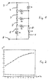
- Fig. 1 As shown in the AC-powered induction motor has a main winding 1 and three auxiliary windings 2, 3 and 4, which are switchable via switches T1 to T4 either in series or parallel to the main winding 1. Furthermore, the motor has a parallel to the main winding 1 switched operating capacitor 5 and a switch T0 connected in series therewith.
- the electronic switches T0 to T4 are triacs, but other suitable electronic switches may be used. With the aid of the switches T1 to T4, the motor can be operated in four different basic configurations, corresponding to four different rated speeds. These rated speeds differ depending on the load condition of the actual speeds. In the case of Fig.
- the supply voltage is present at terminals 6 and 7.
- a measuring resistor 8 is connected, which is provided for current measurement in the main winding, wherein not the amplitude of the current waveform is determined, but only time of zero crossing, since only during the zero crossing, the switches T1 to T4 can be switched without load.
- a phase shift between two suitable variables on the motor is measured to determine the load state of the motor, for example for determining the speed of the motor.
- the upper curve according to Fig. 2 is shown as a function of the reciprocal speed resulting phase shift, which results when one compares the voltage between the terminals 6 and 7 on the one hand with the current flowing through the main winding 1 current, namely at one of the above four basic switch positions of the engine , As based on this in Fig. 2 top curve, it can be assigned a reciprocal value of the speed or a speed based on this curve of the phase shift of each phase shift. Once this curve has been determined, the actual speed in the respective shift position can only be determined by determining the phase shift. So there is a clear correlation between phase shift and speed given.
- Fig. 2 In order to obtain as clear and meaningful an assignment as possible, it is essential to measure the phase shift between suitable magnitudes on the motor.
- Fig. 2 is only an example of a lower curve shown, in which such an assignment is not or at least so given that it is technically difficult or impossible to detect.
- the lower curve shown is the cosine ⁇ , ie the phase shift between current and voltage at the terminals 6, 7 of the motor during operation.
- Particularly suitable for measuring the phase shift is the voltage at one or more parallel to the main winding 8 switched auxiliary windings and the current flowing through the operating capacitor 5, or flows through the main winding 1, or by a series connected to the main winding 1 auxiliary winding 2, 3 or 4 flows.
- phase shift between the above-mentioned electrical quantities on the motor either at least one of the auxiliary windings 2, 3, 4 in series to the main winding 1 or else must lie parallel to it, it is particularly appropriate, the phase shift between the current flowing through the main winding 1 current on the one hand and the voltage applied to one or more auxiliary windings 2, 3, 4 connected in series with the main winding, on the other hand, or the voltage applied in parallel to the main winding 1, auxiliary winding 2, 3 or 4, for example.
- the measurement is expediently carried out in each case at the zero crossing of the individual variables, wherein the time between the zero crossings is to be determined.
- the latter measuring arrangement is particularly of particular advantage because then the already existing measuring resistor 8 and in the evaluation electronics anyway pending zero crossing signal of the current can be used, so that only the zero crossing of the voltage at the connected in series or parallel to the main winding Auxiliary winding is to determine and then determine the respective time interval.
- the zero crossing measurement offers compared to the otherwise Performance measurements conventional amplitude measurements significant advantages, since no complex analog-to-digital converter is required for the signal processing in the course of the evaluation, which usually takes place in a microprocessor, since the analog measurement signal with little electronic effort directly into a digitally evaluable signal can be transferred.
- Fig. 1 shown motor used to drive a centrifugal pump assembly for a heating system
- the actual flow rate of the pump can be determined based on the above phase shift, which is within certain limits based on the respective switching position approximately inversely proportional to the speed of the motor.
- Fig. 2 illustrated upper curve thus represents the flow rate of the pump as a function of the phase shift between two electrical variables on the engine.
- Fig. 3 show twenty-four curves (four basic switch positions and twenty intermediate shift positions).
- Fig. 4 is the HQ diagram for these twenty-four switch positions shown, which can be determined in a known manner.
- Illustrated curves A, B, C and D relate to the basic switching positions, while the curve indicated by E by way of example is an intermediate switching position.
- the HQ diagram according to Fig. 4 is known for each switching position, ie the course of flow and head is known and if on the other hand according to the corresponding curves in Fig.
Landscapes
- Engineering & Computer Science (AREA)
- Power Engineering (AREA)
- Control Of Ac Motors In General (AREA)
Claims (15)
- Procédé pour l'enregistrement d'au moins un paramètre de l'état de charge d'un moteur asynchrone alimenté en courant alternatif avec un enroulement principal (1), avec au moins un enroulement auxiliaire (2, 3, 4) et avec au moins un condensateur (5), dans lequel le paramètre caractérisant l'état de charge est déterminé à l'aide du décalage de phase entre au moins deux grandeurs électriques sur le moteur, caractérisé en ce que le paramètre caractérisant l'état de charge est déterminé à l'aide du décalage de phase entre au moins deux grandeurs électriques, dépendant de la charge respectivement dans leur position de phase, sur le moteur, les grandeurs électriques, entre lesquelles le décalage de phase est déterminé, se modifiant réciproquement dans le sens contraire par le spectre de charge dans la phase.
- Procédé selon la revendication 1, caractérisé en ce que le décalage de phase est déterminé par la mesure de temps entre les passages par zéro des grandeurs électriques respectives.
- Procédé selon l'une des revendications précédentes, caractérisé en ce que le décalage de phase entre la tension, qui est appliquée sur l'enroulement auxiliaire ou les enroulements auxiliaires (2, 3, 4) montés en amont de l'enroulement principal (1), et une autre grandeur électrique sur le moteur est déterminé.
- Procédé selon la revendication 3, caractérisé en ce que l'autre grandeur électrique est le courant circulant à travers l'enroulement principal (1) du moteur.
- Procédé selon la revendication 3, caractérisé en ce que l'autre grandeur électrique est la tension s'appliquant sur un enroulement auxiliaire (2, 3, 4) branché en parallèle avec l'enroulement principal (1).
- Procédé selon la revendication 3, caractérisé en ce que l'autre grandeur électrique est la tension s'appliquant sur l'enroulement principal (1).
- Procédé selon la revendication 3, caractérisé en ce que l'autre grandeur électrique est le courant circulant dans l'enroulement auxiliaire ou les enroulements auxiliaires (2, 3, 4) branchés en série avec l'enroulement principal (1).
- Procédé selon la revendication 3, caractérisé en ce que l'autre grandeur électrique est le courant circulant dans le condensateur de service (5).
- Procédé selon la revendication 3, caractérisé en ce que l'autre grandeur électrique est la tension s'appliquant sur le condensateur de service (5).
- Procédé selon l'une des revendications précédentes, caractérisé en ce que le décalage de phase entre un enroulement auxiliaire (2, 3, 4) branché en parallèle avec l'enroulement principal (1) et le courant circulant dans l'enroulement principal est déterminé.
- Procédé selon l'une des revendications précédentes pour un moteur asynchrone avec plusieurs enroulements auxiliaires (2, 3, 4) qui peuvent être commutés au moyen d'interrupteurs électroniques (T1 à T4) au choix en série ou en parallèle avec l'enroulement principal (1), caractérisé en ce que, à l'aide de la position de phase enregistrée pour la détermination du décalage de phase dans l'enroulement principal (1), la commande des interrupteurs électroniques (T1 à T4) s'effectue de telle sorte que des opérations de commutation ne s'effectuent que lors du passage par zéro du courant de l'enroulement principal (1).
- Procédé selon l'une des revendications précédentes, caractérisé en ce que, pour l'enregistrement d'au moins un paramètre de l'état de charge du moteur, dans le cas où tous les enroulements auxiliaires (2, 3, 4) sont branchés en parallèle avec l'enroulement principal (1), un enroulement auxiliaire (2, 3, 4) est branché pendant un court instant en série avec l'enroulement principal (1) dans le but de la mesure du décalage de phase.
- Procédé selon la revendication 12, caractérisé en ce que la durée de commutation pour des tâches de mesure se situe entre une demi-période et cinq périodes de la fréquence du réseau.
- Moteur asynchrone à courant alternatif avec un enroulement principal (1), avec au moins un condensateur (5) et avec au moins un enroulement auxiliaire (2, 3, 4), qui peut être commuté au moyen d'un interrupteur électronique (D1 à D4) en parallèle ou en série avec l'enroulement principal (1), une résistance de mesure (8) pour l'enregistrement du courant circulant dans l'enroulement principal (1) étant branchée en série avec l'enroulement principal (1), caractérisé en ce qu'un appareil est prévu dans le moteur pour l'enregistrement du décalage de phase entre au moins deux grandeurs électriques dépendant de la charge qui se modifient réciproquement dans le sens contraire par le spectre de charge dans la phase, la résistance de mesure (8) formant une partie de cet appareil.
- Moteur à synchrone à courant alternatif selon la revendication 14, caractérisé en ce qu'il fait partie d'un ensemble de pompe de circulation de chauffage pourvu d'une pompe centrifuge.
Applications Claiming Priority (2)
| Application Number | Priority Date | Filing Date | Title |
|---|---|---|---|
| DE19815232A DE19815232A1 (de) | 1998-04-04 | 1998-04-04 | Verfahren zur Erfassung eines Parameters eines Asynchronmotors |
| DE19815232 | 1998-04-04 |
Publications (4)
| Publication Number | Publication Date |
|---|---|
| EP0948126A2 EP0948126A2 (fr) | 1999-10-06 |
| EP0948126A3 EP0948126A3 (fr) | 2001-08-01 |
| EP0948126B1 EP0948126B1 (fr) | 2004-05-12 |
| EP0948126B2 true EP0948126B2 (fr) | 2009-09-09 |
Family
ID=7863662
Family Applications (1)
| Application Number | Title | Priority Date | Filing Date |
|---|---|---|---|
| EP99105537A Expired - Lifetime EP0948126B2 (fr) | 1998-04-04 | 1999-03-18 | Dispositif de détection de paramètre d'un moteur asynchrone |
Country Status (2)
| Country | Link |
|---|---|
| EP (1) | EP0948126B2 (fr) |
| DE (2) | DE19815232A1 (fr) |
Families Citing this family (6)
| Publication number | Priority date | Publication date | Assignee | Title |
|---|---|---|---|---|
| DE10160203A1 (de) * | 2001-12-07 | 2003-06-18 | Wilo Gmbh | Selbsttätige Leistungsstufenanpassung |
| FR2846488B1 (fr) * | 2002-10-25 | 2005-01-14 | Pompes Salmson Sa | Procede de mesure de la puissance fournie par un moteur |
| JP4438281B2 (ja) * | 2002-11-15 | 2010-03-24 | ダイキン工業株式会社 | ポンプ駆動方法およびその装置 |
| ES2324997T3 (es) * | 2003-10-07 | 2009-08-21 | Askoll Holding S.R.L. | Metodo para controlar y accionar una bomba para electrodomesticos. |
| DE102005036802C5 (de) * | 2005-08-02 | 2008-10-30 | Jürgen Gattner | Verfahren und Vorrichtung zur Steigerung der Effizienz eines Elektromotors |
| DE102011056865B3 (de) * | 2011-12-22 | 2013-01-03 | Az Pokorny S.R.O. | Einrichtung zur Steuerung einer Heizungsumwälzpumpe und Steuerungsverfahren |
Citations (2)
| Publication number | Priority date | Publication date | Assignee | Title |
|---|---|---|---|---|
| DE4031708A1 (de) † | 1990-10-06 | 1992-04-16 | Telefunken Electronic Gmbh | Differenzdruckregelung fuer ein pumpsystem |
| EP0629037A1 (fr) † | 1993-06-08 | 1994-12-14 | POMPES SALMSON Société Anonyme à directoire dite: | Procédé et dispositif de régulation de l'alimentation d'un moteur électrique asynchrone |
Family Cites Families (8)
| Publication number | Priority date | Publication date | Assignee | Title |
|---|---|---|---|---|
| US4454462A (en) * | 1980-10-20 | 1984-06-12 | Neha International | Power factor motor controller |
| GB2128425B (en) * | 1982-10-08 | 1986-06-25 | Newelec Pretoria | Stall detection apparatus |
| JP2538558B2 (ja) * | 1984-12-18 | 1996-09-25 | 株式会社東芝 | 誘導電動機の負荷状態検知装置 |
| AU569646B2 (en) * | 1984-12-18 | 1988-02-11 | Toshiba, Kabushiki Kaisha | Detecting critical rotation speed of an induction motor |
| DE3607162A1 (de) * | 1986-03-05 | 1987-09-10 | Grundfos As | Wechselstrommotor fuer insbesondere umwaelzpumpen |
| DE3628284A1 (de) * | 1986-08-20 | 1988-02-25 | Bosch Gmbh Robert | Verfahren und anordnung zum ermitteln des differenzdruckes von umwaelzpumpen |
| DE4337614A1 (de) * | 1993-11-04 | 1995-05-11 | Telefunken Microelectron | Differenzdruckregelung für ein Pumpsystem |
| US5808441A (en) * | 1996-06-10 | 1998-09-15 | Tecumseh Products Company | Microprocessor based motor control system with phase difference detection |
-
1998
- 1998-04-04 DE DE19815232A patent/DE19815232A1/de not_active Ceased
-
1999
- 1999-03-18 EP EP99105537A patent/EP0948126B2/fr not_active Expired - Lifetime
- 1999-03-18 DE DE59909439T patent/DE59909439D1/de not_active Expired - Lifetime
Patent Citations (2)
| Publication number | Priority date | Publication date | Assignee | Title |
|---|---|---|---|---|
| DE4031708A1 (de) † | 1990-10-06 | 1992-04-16 | Telefunken Electronic Gmbh | Differenzdruckregelung fuer ein pumpsystem |
| EP0629037A1 (fr) † | 1993-06-08 | 1994-12-14 | POMPES SALMSON Société Anonyme à directoire dite: | Procédé et dispositif de régulation de l'alimentation d'un moteur électrique asynchrone |
Also Published As
| Publication number | Publication date |
|---|---|
| DE59909439D1 (de) | 2004-06-17 |
| DE19815232A1 (de) | 1999-10-07 |
| EP0948126A3 (fr) | 2001-08-01 |
| EP0948126A2 (fr) | 1999-10-06 |
| EP0948126B1 (fr) | 2004-05-12 |
Similar Documents
| Publication | Publication Date | Title |
|---|---|---|
| DE3706659C2 (fr) | ||
| DE3736303C2 (fr) | ||
| DE69422162T2 (de) | Verfahren und Vorrichtung zum Regeln der Drehzahl eines Waschmaschinenmotors | |
| DE4137559A1 (de) | Einrichtung zur erfassung mindestens einer zustandsgroesse eines buerstenlosen gleichstrommotors | |
| DE3101511A1 (de) | Verfahren und anordnung zur belastungsermittlung von durch einen elektromotor angetriebenen geraeten | |
| EP1191676B1 (fr) | Procédé de détection de la vitesse de rotation d'un moteur à courant alternatif et système de commande de moteur | |
| DE3900464A1 (de) | Vorrichtung zur rotorlage- und drehzahlermittlung eines elektromotors | |
| EP1514342B1 (fr) | Procede et ensemble de circuits pour faire fonctionner des moteurs pas a pas | |
| EP0948126B2 (fr) | Dispositif de détection de paramètre d'un moteur asynchrone | |
| DE4031708C2 (de) | Verfahren zur Differenzdruckregelung eines von einem Einphasen-Kondensatormotor angetriebenen Pumpsystems und Schaltungsanordnung zur Durchführung des Verfahrens | |
| DE69312183T2 (de) | Steuerungsverfahren eines Elektromotors zum Antrieb einer Kreiselpumpe | |
| DE4039886C2 (de) | Verfahren und Anordnung zur Kommutierung oder zur Drehlageerkennung des Rotors eines bürstenlosen Gleichstrommotors ohne externe Positionssensoren | |
| DE69029711T2 (de) | Schaltungsanordnung zur Steuerung eines Freikolbenmotors, insbesondere eines Kühlschrankkompressors | |
| DE69016794T2 (de) | Verfahren und vorrichtung zum starten einer elektrischen maschine mit variabler reluktanz. | |
| DE19709596C2 (de) | Verfahren zum Identifizieren eines elektrischen Motors für Wechselstrom | |
| DE4031709C2 (de) | Differenzdruckregelung für ein Pumpsystem | |
| DE2318758A1 (de) | Verfahren und einrichtung zur ueberwachung von energie-verbrauchersystemen | |
| DE10331934B3 (de) | Verfahren zum Steuern eines Waschmaschinen-Motors und Waschmaschinen-Motor | |
| DE102019217414A1 (de) | Elektrische Maschine | |
| EP0803971B1 (fr) | Procédé et dispositif pour commander la vitesse de rotation d'un moteur monophasé à induction dans des dispositifs de ventilisation ou similaire en fonction de pression | |
| DE4437750A1 (de) | Verfahren und Schaltungsanordnung zur Messung der Drehzahl eines Elektromotoros | |
| DE2151801A1 (de) | Messanordnung | |
| DE102007053755A1 (de) | Verfahren und Einrichtung zur Überwachung einer Läufertemperatur einer permanent erregten elektrischen Maschine | |
| DE102006020676A1 (de) | Verfahren zum Betrieb eines elektronisch kommutierten Motors, und Motor zur Durchführung eines solchen Verfahrens | |
| DD258467A1 (de) | Anordnung zur bestimmung der leistung und/oder des moments an induktionsmotoren |
Legal Events
| Date | Code | Title | Description |
|---|---|---|---|
| PUAI | Public reference made under article 153(3) epc to a published international application that has entered the european phase |
Free format text: ORIGINAL CODE: 0009012 |
|
| AK | Designated contracting states |
Kind code of ref document: A2 Designated state(s): DE FR GB IT |
|
| AX | Request for extension of the european patent |
Free format text: AL;LT;LV;MK;RO;SI |
|
| PUAL | Search report despatched |
Free format text: ORIGINAL CODE: 0009013 |
|
| AK | Designated contracting states |
Kind code of ref document: A3 Designated state(s): AT BE CH CY DE DK ES FI FR GB GR IE IT LI LU MC NL PT SE |
|
| AX | Request for extension of the european patent |
Free format text: AL;LT;LV;MK;RO;SI |
|
| 17P | Request for examination filed |
Effective date: 20011201 |
|
| 17Q | First examination report despatched |
Effective date: 20020122 |
|
| AKX | Designation fees paid |
Free format text: DE FR GB IT |
|
| GRAP | Despatch of communication of intention to grant a patent |
Free format text: ORIGINAL CODE: EPIDOSNIGR1 |
|
| GRAS | Grant fee paid |
Free format text: ORIGINAL CODE: EPIDOSNIGR3 |
|
| GRAA | (expected) grant |
Free format text: ORIGINAL CODE: 0009210 |
|
| AK | Designated contracting states |
Kind code of ref document: B1 Designated state(s): DE FR GB IT |
|
| REG | Reference to a national code |
Ref country code: GB Ref legal event code: FG4D Free format text: NOT ENGLISH |
|
| REF | Corresponds to: |
Ref document number: 59909439 Country of ref document: DE Date of ref document: 20040617 Kind code of ref document: P |
|
| GBT | Gb: translation of ep patent filed (gb section 77(6)(a)/1977) |
Effective date: 20040825 |
|
| ET | Fr: translation filed | ||
| PLAQ | Examination of admissibility of opposition: information related to despatch of communication + time limit deleted |
Free format text: ORIGINAL CODE: EPIDOSDOPE2 |
|
| PLBI | Opposition filed |
Free format text: ORIGINAL CODE: 0009260 |
|
| PLBQ | Unpublished change to opponent data |
Free format text: ORIGINAL CODE: EPIDOS OPPO |
|
| PLAQ | Examination of admissibility of opposition: information related to despatch of communication + time limit deleted |
Free format text: ORIGINAL CODE: EPIDOSDOPE2 |
|
| PLAR | Examination of admissibility of opposition: information related to receipt of reply deleted |
Free format text: ORIGINAL CODE: EPIDOSDOPE4 |
|
| PLBQ | Unpublished change to opponent data |
Free format text: ORIGINAL CODE: EPIDOS OPPO |
|
| PLAB | Opposition data, opponent's data or that of the opponent's representative modified |
Free format text: ORIGINAL CODE: 0009299OPPO |
|
| PLAB | Opposition data, opponent's data or that of the opponent's representative modified |
Free format text: ORIGINAL CODE: 0009299OPPO |
|
| PLAQ | Examination of admissibility of opposition: information related to despatch of communication + time limit deleted |
Free format text: ORIGINAL CODE: EPIDOSDOPE2 |
|
| PLAR | Examination of admissibility of opposition: information related to receipt of reply deleted |
Free format text: ORIGINAL CODE: EPIDOSDOPE4 |
|
| PLAX | Notice of opposition and request to file observation + time limit sent |
Free format text: ORIGINAL CODE: EPIDOSNOBS2 |
|
| PLBQ | Unpublished change to opponent data |
Free format text: ORIGINAL CODE: EPIDOS OPPO |
|
| 26 | Opposition filed |
Opponent name: WILO AG Effective date: 20050214 |
|
| R26 | Opposition filed (corrected) |
Opponent name: WILO AG Effective date: 20050214 |
|
| R26 | Opposition filed (corrected) |
Opponent name: WILO AG Effective date: 20050214 |
|
| PLAF | Information modified related to communication of a notice of opposition and request to file observations + time limit |
Free format text: ORIGINAL CODE: EPIDOSCOBS2 |
|
| PLBB | Reply of patent proprietor to notice(s) of opposition received |
Free format text: ORIGINAL CODE: EPIDOSNOBS3 |
|
| PLAB | Opposition data, opponent's data or that of the opponent's representative modified |
Free format text: ORIGINAL CODE: 0009299OPPO |
|
| RIC2 | Information provided on ipc code assigned after grant |
Ipc: H02P 25/04 20060101AFI20090331BHEP |
|
| PUAH | Patent maintained in amended form |
Free format text: ORIGINAL CODE: 0009272 |
|
| STAA | Information on the status of an ep patent application or granted ep patent |
Free format text: STATUS: PATENT MAINTAINED AS AMENDED |
|
| 27A | Patent maintained in amended form |
Effective date: 20090909 |
|
| AK | Designated contracting states |
Kind code of ref document: B2 Designated state(s): DE FR GB IT |
|
| PGFP | Annual fee paid to national office [announced via postgrant information from national office to epo] |
Ref country code: IT Payment date: 20120306 Year of fee payment: 14 |
|
| PGFP | Annual fee paid to national office [announced via postgrant information from national office to epo] |
Ref country code: GB Payment date: 20130218 Year of fee payment: 15 Ref country code: FR Payment date: 20130227 Year of fee payment: 15 |
|
| PGFP | Annual fee paid to national office [announced via postgrant information from national office to epo] |
Ref country code: DE Payment date: 20130514 Year of fee payment: 15 |
|
| REG | Reference to a national code |
Ref country code: DE Ref legal event code: R119 Ref document number: 59909439 Country of ref document: DE |
|
| GBPC | Gb: european patent ceased through non-payment of renewal fee |
Effective date: 20140318 |
|
| REG | Reference to a national code |
Ref country code: FR Ref legal event code: ST Effective date: 20141128 |
|
| REG | Reference to a national code |
Ref country code: DE Ref legal event code: R119 Ref document number: 59909439 Country of ref document: DE Effective date: 20141001 |
|
| PG25 | Lapsed in a contracting state [announced via postgrant information from national office to epo] |
Ref country code: GB Free format text: LAPSE BECAUSE OF NON-PAYMENT OF DUE FEES Effective date: 20140318 Ref country code: FR Free format text: LAPSE BECAUSE OF NON-PAYMENT OF DUE FEES Effective date: 20140331 Ref country code: DE Free format text: LAPSE BECAUSE OF NON-PAYMENT OF DUE FEES Effective date: 20141001 |
|
| PG25 | Lapsed in a contracting state [announced via postgrant information from national office to epo] |
Ref country code: IT Free format text: LAPSE BECAUSE OF NON-PAYMENT OF DUE FEES Effective date: 20140318 |