EP0948224A2 - Méthode pour la transmission de données "sans-fil" et station intermédiaire - Google Patents
Méthode pour la transmission de données "sans-fil" et station intermédiaire Download PDFInfo
- Publication number
- EP0948224A2 EP0948224A2 EP98114704A EP98114704A EP0948224A2 EP 0948224 A2 EP0948224 A2 EP 0948224A2 EP 98114704 A EP98114704 A EP 98114704A EP 98114704 A EP98114704 A EP 98114704A EP 0948224 A2 EP0948224 A2 EP 0948224A2
- Authority
- EP
- European Patent Office
- Prior art keywords
- radio
- base station
- terminal
- data
- intermediate station
- Prior art date
- Legal status (The legal status is an assumption and is not a legal conclusion. Google has not performed a legal analysis and makes no representation as to the accuracy of the status listed.)
- Granted
Links
Images
Classifications
-
- H—ELECTRICITY
- H04—ELECTRIC COMMUNICATION TECHNIQUE
- H04W—WIRELESS COMMUNICATION NETWORKS
- H04W88/00—Devices specially adapted for wireless communication networks, e.g. terminals, base stations or access point devices
- H04W88/02—Terminal devices
Definitions
- the invention relates to a method for wireless Data transmission between a terminal and one Base station according to the type of independent claim 1 and from an intermediate station of the genus of independent claim 7.
- DECT repeater is usually placed on the edge of a radio cell.
- the cordless telephone designed as a handset can establish a connection to the DECT repeater outside the radio cell, ie if the base station spanning the radio cell is too far away, the DECT repeater then establishes a connection to the base station and routes the data between the DECT handset and the base station transparently.
- the DECT repeater thus acts in the direction of the DECT handset like a base station and in the direction of the base station like a DECT handset.
- features of independent claim 7 the advantage that data between the terminal and one in a radio cell of the base station Intermediate station are transmitted by optical signals and that the data between the intermediate station and the Base station by radio signals, preferably according to the DECT standard be transmitted.
- end devices with an optical transmitter and / or receiver unit with the base station designed for radio communication are transmitted.
- the intermediate station makes it easy a transition from end devices with optical interface in a radio system enables.
- the Base station received data to a connected data or Telecommunications network are transmitted.
- the Cordless telephony system can thus be used at both local and also be connected to public networks, so that from the Access to an end device with an optical interface remote, on the data or telecommunications network connected computer is possible. Because access is via Radio system is not a separate interface of the optical transmission system to local or public Network required.
- Another advantage is that the intermediate station of radio signals received by a second terminal derived radio signals to the base station.
- the functionality of the intermediate station significantly expanded by using the intermediate station as well Repeater for outside of the base station radio devices located in the open cell or Cordless phones work as well as the transition from Devices with an optical interface in the radio system enables.
- the repeater function for End devices designed as radio devices or cordless phones and the transition from end devices with an optical interface into the radio system into a single intermediate station Effort and costs saved, so that for the transition of Devices with an optical interface in the radio system no separate stopover is required.
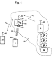
- FIG. 1 shows a block diagram of a Radio system to which a device with an optical interface is connected
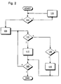
- Figure 2 is a flow chart for the Operation of the method according to the invention.
- 5 denotes a base station, for example a cordless phone system.
- the cordless phone system can be based on the DECT standard, for example be.
- the radio system can also be a Mobile radio system, for example according to the GSM standard act.
- a first transmit / receive antenna 50 connected at the base station 5 .
- the base station 5 spans a radio cell 65.
- a Printer 30 can be connected, which is shown in FIG is within the radio cell 65, but is also could be outside the radio cell 65.
- base station 5 at least one data or telecommunications network 15, 20, 25 be connected. It can be a local or act a public network. According to the embodiment According to FIG.
- the base station 5 is connected to an ISDN network 15 (Integrated Services Data Network), a local network 20 and a data network 25 designed as an interpet is connected. In this way, the base station 5 with subscribers of these data or telecommunications networks 15, 20, 25 communicate. These participants can go far outside the Radio cell 65 may be arranged. Within the radio cell 65, however, preferably in an edge region of the radio cell 65 an intermediate station 10 is arranged. The intermediate station 10 comprises a radio transmission / reception unit 35 to which one second transmitting / receiving antenna 55 is connected. Between the intermediate station 10 and the base station 5 can thus a first radio connection 70 are established, depending on Use of the underlying radio standard a DECT radio connection, a GSM radio link or the like can be.
- ISDN network 15 Integrated Services Data Network
- the DECT standard used so that the first Radio link 70 represents a DECT radio link.
- Terminal 40 as a cordless phone, as a mobile phone, as Mobile radio device as a handheld radio, as a company radio or the like can be formed.
- the second terminal 40 as a cordless phone after DECT standard.
- a third transmit / receive antenna 60 is connected to the second terminal 40 .
- a second radio connection 75 can be established, the according to the described embodiment of the DECT standard underlying.
- the intermediate station 10 works thus as a relay station in the radio system described and this increases the range of the base station 5.
- the second terminal 40 is outside the radio cell 65 there is no direct radio connection with the Pick up base station 5. However, it can be the second Establish radio connection 75 to intermediate station 10.
- the Intermediate station 10 then establishes the first radio connection 70 to base station 5 and routes accordingly Radio data signals between the second terminal 40 and the Base station 5 transparent.
- the intermediate station 10 acts in the direction of the second terminal 40 like one Base station and in the direction of base station 5 as a Terminal. Conversely, in a corresponding manner Base station 5 a radio connection via the intermediate station 10 to the second terminal 40.
- the intermediate station 10 further comprises an optical one Transceiver-trained interface 45.
- Die Interface 45 can be used, for example, for sending and Receive optical signals in one Infrared frequency range can be formed.
- the Interface 45 for example, according to the IrDA standard (Infrared Data Association).
- the conversion unit 80 is the radio transmission / reception unit 35 the interface 45 connected.
- a first terminal 1 is arranged.
- the first terminal 1 can, however, also be arranged within the radio cell 65.
- the first terminal 1 comprises an optical transmitter / receiver unit 85.
- the optical transmitter / receiver unit 85 of the first terminal 1 can also be optical Signals, for example, in an infrared wavelength range send and receive.
- the conversion unit 80 can convert between optical data signals and Radio data signals take place so that the first terminal 1 can also communicate with the base station 5.
- both between the first terminal 1 and a participant one of the data or Telecommunications networks 15, 20, 25 and the printer 30 as also between the second terminal 40 and a subscriber one of the data or telecommunications networks 15, 20, 25 or the printer 30 data are exchanged.
- So can for example from the first terminal 1 or from the second Terminal 40 data on the intermediate station 10 to the Base station 5 transmitted and from there to a subscriber one of the data or telecommunications networks 15, 20, 25 or forwarded to printer 30.
- printer 30 a any data output unit can be connected and in correspondingly with the first terminal 1 or the second terminal 40 communicate.
- the Base station 5 a local database server, a home automation system etc. connected and via the base station 5 and the intermediate station 10 with the first terminal 1 and / or the second terminal 40 in the manner described communicate.
- FIG 2 is a flow chart for an example Operation of the method according to the invention shown.
- the intermediate station 10 checks whether there is a connection request from the first terminal 1. Is if this is the case, the program branches to a program point 105, otherwise the program branches to a program point 125. A from the first terminal 1 outgoing connection request thereby by one of the transmitting / receiving unit 85 of the first Terminal 1 emitted, described in Embodiment lying in the infrared frequency range optical request signal of the intermediate station 10 communicated.
- the Intermediate station 10 a radio channel to the base station 5.
- Program point 125 will go through a waiting loop. The program then branches back to program point 100.
- Program point 105 is branched to a program point 110.
- the intermediate station 10 checks whether the first terminal 1 optical data signals in the interface 45 are received. If this is the case, it becomes one Program point 115 branches, otherwise it becomes a Program item 130 branches. Changes at program point 115 the conversion unit 80 the optical data signals in Radio data signals and causes the radio transmission / -Receiving unit 35 for radiating the radio data signals the base station 5. Then becomes a program item 120 branches. At program point 120 the checks Intermediate station 10, whether the connection was ended. Is if this is the case, the program section is exited, otherwise the program branches back to program point 110.
- Program point 130 checks the intermediate station 10 whether Radio data signals from the base station 5 in the radio transmission / -Receiving unit 35 were received and whether this Radio data signals are addressed to the first terminal 1. If this is the case, then program point 135 branches, otherwise the program branches to program point 120.
- the conversion unit 80 converts the Radio data signals into optical data signals.
- the optical Data signals are then generated by means of this Embodiment designed as an infrared connection optical connection 90 to the first terminal 1 of the Interface 45 emitted. Then becomes Program item 120 branches.
- unidirectional data transmission can also be provided be, depending on the direction of transmission then on the first Terminal 1 only one optical transmitter or only one optical receiving device is to be provided and Interface 45 is only an optical receiving device or must include an optical transmitter.
- the intermediate station 10 is also only a radio transmission unit or a radio reception unit to provide. In this case, however, is between the second Terminal 40 and base station 5 no longer exchange data possible.
- the intermediate station 10 can in the typical Areas of application for radio repeaters, for example DECT repeaters for large office spaces, for factory buildings or the like in addition to the relay function for corresponding Two-way radios, for example for DECT cordless phones Transition from end devices with an optical interface to the appropriate radio system can be realized.
- radio repeaters for example DECT repeaters for large office spaces, for factory buildings or the like
- relay function for corresponding Two-way radios for example for DECT cordless phones Transition from end devices with an optical interface to the appropriate radio system can be realized.
Landscapes
- Engineering & Computer Science (AREA)
- Computer Networks & Wireless Communication (AREA)
- Signal Processing (AREA)
- Mobile Radio Communication Systems (AREA)
Applications Claiming Priority (2)
| Application Number | Priority Date | Filing Date | Title |
|---|---|---|---|
| DE1997151845 DE19751845A1 (de) | 1997-11-22 | 1997-11-22 | Verfahren zur drahtlosen Datenübertragung und Zwischenstation |
| DE19751845 | 1997-11-22 |
Publications (3)
| Publication Number | Publication Date |
|---|---|
| EP0948224A2 true EP0948224A2 (fr) | 1999-10-06 |
| EP0948224A3 EP0948224A3 (fr) | 2000-05-24 |
| EP0948224B1 EP0948224B1 (fr) | 2007-11-07 |
Family
ID=7849550
Family Applications (1)
| Application Number | Title | Priority Date | Filing Date |
|---|---|---|---|
| EP98114704A Revoked EP0948224B1 (fr) | 1997-11-22 | 1998-08-05 | Méthode pour la transmission de données "sans-fil" et station intermédiaire |
Country Status (2)
| Country | Link |
|---|---|
| EP (1) | EP0948224B1 (fr) |
| DE (2) | DE19751845A1 (fr) |
Families Citing this family (1)
| Publication number | Priority date | Publication date | Assignee | Title |
|---|---|---|---|---|
| DE102010005007A1 (de) * | 2010-01-19 | 2011-07-21 | Frieters, Oliver, 86316 | Steuerungs-Baukasten |
Family Cites Families (3)
| Publication number | Priority date | Publication date | Assignee | Title |
|---|---|---|---|---|
| KR890702353A (ko) * | 1987-11-13 | 1989-12-23 | 원본미기재 | 통신장치 |
| FI109496B (fi) * | 1992-08-18 | 2002-08-15 | Nokia Corp | Laitteisto ja menetelmä digitaalisen infrapunavälitteisen tiedonsiirron järjestämiseksi radiopuhelinlaitteen perusosan ja toisen laitteen välillä |
| GB2301987B (en) * | 1995-06-05 | 2000-01-12 | Nokia Mobile Phones Ltd | Radio telephone text transmission system |
-
1997
- 1997-11-22 DE DE1997151845 patent/DE19751845A1/de not_active Withdrawn
-
1998
- 1998-08-05 EP EP98114704A patent/EP0948224B1/fr not_active Revoked
- 1998-08-05 DE DE59814119T patent/DE59814119D1/de not_active Expired - Lifetime
Also Published As
| Publication number | Publication date |
|---|---|
| DE19751845A1 (de) | 1999-05-27 |
| EP0948224A3 (fr) | 2000-05-24 |
| EP0948224B1 (fr) | 2007-11-07 |
| DE59814119D1 (de) | 2007-12-20 |
Similar Documents
| Publication | Publication Date | Title |
|---|---|---|
| DE69323942T2 (de) | Infrarotverbindung zwischen einem Sendeempfänger und einem externen Gerät | |
| DE69120204T2 (de) | Mobiles Funkkommunikationssystem mit mobiler Basisstation und tragbares Gerät als Mobilstation | |
| DE69730493T2 (de) | Alternatives leitweglenkungssystem für mobiltelefongespräche | |
| EP0849965A1 (fr) | Téléphone sans fil | |
| DE60037157T2 (de) | Multimode Mobiltelefongerät | |
| DE19547809A1 (de) | Mobilfunkgerät mit integriertem Faxgerät | |
| DE4320047A1 (de) | Schnurloses Telefon | |
| EP1044578B1 (fr) | Procede permettant de faire fonctionner un terminal de telecommunications et terminal de telecommunications | |
| DE69611244T2 (de) | Drahtlose multi-zellulare funk-telekommunikationsanordnung | |
| EP1121784B1 (fr) | Station de base pour un systeme radio pour courtes distances, et systeme de communication de donnees | |
| EP0948224B1 (fr) | Méthode pour la transmission de données "sans-fil" et station intermédiaire | |
| EP1137240B1 (fr) | Radiotéléphone | |
| DE10135023A1 (de) | Schnittstelle | |
| EP0797366A2 (fr) | Transmission de données dans un canal de parole pour systèmes DECT | |
| WO1996038988A1 (fr) | Systeme de telecommunication mobile universel | |
| DE19616239C2 (de) | Verfahren zum Anschluß von Basisstationen eines schnurlosen Kommunikationssystems an eine ISDN-Nebenstellenanlage | |
| DE10016622B4 (de) | Verfahren zum Steuern von Leistungsmerkmalen in einem Funknetz und Anordnungen zur Realisierung des Verfahrens | |
| EP0800303A2 (fr) | Installation téléphonique pour des téléphones sans fil | |
| DE19521453A1 (de) | Vorrichtung und Verfahren zur drahtlosen Kommunikation mit einer Datenverarbeitungseinrichtung | |
| DE29825268U1 (de) | Zwischenstation | |
| DE19644562C1 (de) | Verfahren zum drahtlosen Austausch von Daten und Telekommunikationseinheit | |
| EP1487174A8 (fr) | Procédé de contrôle de communication entre terminaux utilisant un réseau de trasnfert de données IP | |
| EP1319318B1 (fr) | Installation de telecommunication comprenant une station de base et au moins un element mobile ainsi qu'un repeteur intermediaire | |
| DE4035529C1 (en) | Telephone system with interface to exchange - includes coupling unit for data transmission between subscribers appts. and transceiver of mobile radio telephone | |
| DE10109478A1 (de) | Vorrichtung zur Adaption von Mobilfunkendgeräten an Telekommunikationssysteme in Telekommunikationsnetzen |
Legal Events
| Date | Code | Title | Description |
|---|---|---|---|
| PUAI | Public reference made under article 153(3) epc to a published international application that has entered the european phase |
Free format text: ORIGINAL CODE: 0009012 |
|
| AK | Designated contracting states |
Kind code of ref document: A2 Designated state(s): DE FR GB IT |
|
| AX | Request for extension of the european patent |
Free format text: AL;LT;LV;MK;RO;SI |
|
| PUAL | Search report despatched |
Free format text: ORIGINAL CODE: 0009013 |
|
| AK | Designated contracting states |
Kind code of ref document: A3 Designated state(s): AT BE CH CY DE DK ES FI FR GB GR IE IT LI LU MC NL PT SE |
|
| AX | Request for extension of the european patent |
Free format text: AL;LT;LV;MK;RO;SI |
|
| 17P | Request for examination filed |
Effective date: 20001124 |
|
| AKX | Designation fees paid |
Free format text: DE FR GB IT |
|
| 17Q | First examination report despatched |
Effective date: 20040318 |
|
| GRAP | Despatch of communication of intention to grant a patent |
Free format text: ORIGINAL CODE: EPIDOSNIGR1 |
|
| RAP1 | Party data changed (applicant data changed or rights of an application transferred) |
Owner name: IPCOM GMBH & CO. KG |
|
| GRAS | Grant fee paid |
Free format text: ORIGINAL CODE: EPIDOSNIGR3 |
|
| GRAA | (expected) grant |
Free format text: ORIGINAL CODE: 0009210 |
|
| AK | Designated contracting states |
Kind code of ref document: B1 Designated state(s): DE FR GB IT |
|
| REG | Reference to a national code |
Ref country code: GB Ref legal event code: FG4D Free format text: NOT ENGLISH |
|
| REF | Corresponds to: |
Ref document number: 59814119 Country of ref document: DE Date of ref document: 20071220 Kind code of ref document: P |
|
| GBT | Gb: translation of ep patent filed (gb section 77(6)(a)/1977) |
Effective date: 20080204 |
|
| PLBI | Opposition filed |
Free format text: ORIGINAL CODE: 0009260 |
|
| 26 | Opposition filed |
Opponent name: NOKIA CORPORATOIN Effective date: 20080312 |
|
| ET | Fr: translation filed | ||
| PLBI | Opposition filed |
Free format text: ORIGINAL CODE: 0009260 |
|
| PLAB | Opposition data, opponent's data or that of the opponent's representative modified |
Free format text: ORIGINAL CODE: 0009299OPPO |
|
| 26 | Opposition filed |
Opponent name: RESEARCH IN MOTION LIMITED Effective date: 20080807 Opponent name: NOKIA CORPORATOIN Effective date: 20080312 |
|
| PLAX | Notice of opposition and request to file observation + time limit sent |
Free format text: ORIGINAL CODE: EPIDOSNOBS2 |
|
| PLBB | Reply of patent proprietor to notice(s) of opposition received |
Free format text: ORIGINAL CODE: EPIDOSNOBS3 |
|
| PLAB | Opposition data, opponent's data or that of the opponent's representative modified |
Free format text: ORIGINAL CODE: 0009299OPPO |
|
| RDAF | Communication despatched that patent is revoked |
Free format text: ORIGINAL CODE: EPIDOSNREV1 |
|
| PLAB | Opposition data, opponent's data or that of the opponent's representative modified |
Free format text: ORIGINAL CODE: 0009299OPPO |
|
| R26 | Opposition filed (corrected) |
Opponent name: RESEARCH IN MOTION LIMITED Effective date: 20080807 Opponent name: NOKIA CORPORATION Effective date: 20080312 |
|
| APAH | Appeal reference modified |
Free format text: ORIGINAL CODE: EPIDOSCREFNO |
|
| APBM | Appeal reference recorded |
Free format text: ORIGINAL CODE: EPIDOSNREFNO |
|
| APBP | Date of receipt of notice of appeal recorded |
Free format text: ORIGINAL CODE: EPIDOSNNOA2O |
|
| APBQ | Date of receipt of statement of grounds of appeal recorded |
Free format text: ORIGINAL CODE: EPIDOSNNOA3O |
|
| PGFP | Annual fee paid to national office [announced via postgrant information from national office to epo] |
Ref country code: GB Payment date: 20110831 Year of fee payment: 14 Ref country code: DE Payment date: 20110831 Year of fee payment: 14 Ref country code: FR Payment date: 20110905 Year of fee payment: 14 |
|
| PGFP | Annual fee paid to national office [announced via postgrant information from national office to epo] |
Ref country code: IT Payment date: 20110824 Year of fee payment: 14 |
|
| REG | Reference to a national code |
Ref country code: DE Ref legal event code: R103 Ref document number: 59814119 Country of ref document: DE Ref country code: DE Ref legal event code: R064 Ref document number: 59814119 Country of ref document: DE |
|
| APBU | Appeal procedure closed |
Free format text: ORIGINAL CODE: EPIDOSNNOA9O |
|
| RDAG | Patent revoked |
Free format text: ORIGINAL CODE: 0009271 |
|
| STAA | Information on the status of an ep patent application or granted ep patent |
Free format text: STATUS: PATENT REVOKED |
|
| 27W | Patent revoked |
Effective date: 20120515 |
|
| GBPR | Gb: patent revoked under art. 102 of the ep convention designating the uk as contracting state |
Effective date: 20120515 |
|
| REG | Reference to a national code |
Ref country code: DE Ref legal event code: R107 Ref document number: 59814119 Country of ref document: DE Effective date: 20121011 |