EP0948224B1 - Méthode pour la transmission de données "sans-fil" et station intermédiaire - Google Patents
Méthode pour la transmission de données "sans-fil" et station intermédiaire Download PDFInfo
- Publication number
- EP0948224B1 EP0948224B1 EP98114704A EP98114704A EP0948224B1 EP 0948224 B1 EP0948224 B1 EP 0948224B1 EP 98114704 A EP98114704 A EP 98114704A EP 98114704 A EP98114704 A EP 98114704A EP 0948224 B1 EP0948224 B1 EP 0948224B1
- Authority
- EP
- European Patent Office
- Prior art keywords
- radio
- base station
- data
- terminal
- relay station
- Prior art date
- Legal status (The legal status is an assumption and is not a legal conclusion. Google has not performed a legal analysis and makes no representation as to the accuracy of the status listed.)
- Revoked
Links
- 230000005540 biological transmission Effects 0.000 title claims description 14
- 238000000034 method Methods 0.000 title claims description 14
- 230000003287 optical effect Effects 0.000 claims description 41
- 238000006243 chemical reaction Methods 0.000 claims description 5
- 230000007704 transition Effects 0.000 description 5
- 230000010354 integration Effects 0.000 description 2
- 230000002457 bidirectional effect Effects 0.000 description 1
- 230000001419 dependent effect Effects 0.000 description 1
- 238000010586 diagram Methods 0.000 description 1
Images

Classifications
-
- H—ELECTRICITY
- H04—ELECTRIC COMMUNICATION TECHNIQUE
- H04W—WIRELESS COMMUNICATION NETWORKS
- H04W88/00—Devices specially adapted for wireless communication networks, e.g. terminals, base stations or access point devices
- H04W88/02—Terminal devices
Definitions
- the invention is based on a method for wireless data transmission between a terminal and a base station according to the preamble of the independent claim 1 and of an intermediate station according to the preamble of the independent claim 6.
- DECT Digital Enhanced Cordless Telecommunications
- RP8001 Digital Enhanced Cordless Telecommunications
- DECT Digital Enhanced Cordless Telecommunications
- a cordless telephone designed as a DECT handset can establish a connection to the DECT repeater outside of the radio cell, that is to say if it is too far away from the base station spanning the radio cell.
- the DECT repeater establishes a connection to the base station and routes the data between the DECT-handset and the Base station remains transparent.
- the DECT repeater thus acts in the direction of the DECT handset as a base station and in the direction of the base station as a DECT handset.
- the optically coupled devices in this way each comprise an infrared interface, for example, according to the IrDA standard (Infrared Data Association).
- IrDA interfaces are already built into portable personal computers, PDA's (personal digital assistants), printers and so on.
- the EP-A 585 030 shows a procedure according to which a handset is connected to a mobile unit, which in turn can establish a radio connection to a telecommunications network.
- a PC is connected via a wireless interface to a mobile device, which in turn can transmit data in a telecommunications network.
- the inventive method with the features of independent claim 1 and the intermediate station with the features of independent claim 6 have the advantage that data between the terminal and arranged in a radio cell of the base station intermediate station are transmitted by optical signals and that the data between the Intermediate station and the base station by radio signals, preferably transmitted to the DECT standard.
- terminals with an optical transmitting and / or receiving unit can communicate with the base station designed for radio communication.
- a transition from terminals with optical interface in a radio system is made possible by means of the intermediate station in a simple manner.
- a radio channel to the base station is switched.
- the terminal is connected to the optical interface in a particularly simple manner to the radio communication system, a conventional radio channel can be set up for this connection. Therefore, no special access points may need to be connected by suitable cabling to the base station that organize an optical data exchange with the corresponding terminal. Rather, it is possible to fall back on the existing infrastructure of the radio system for the integration of the terminal with optical interface, which saves effort and costs.
- the cordless telephony system can thus be coupled to both local and public networks, so that the terminal with optical interface access to remote, connected to the data or telecommunications network computer is possible. Since access is via the radio system, no separate interface of the optical transmission system to the local or public network is required.
- a further advantage is that the intermediate station radiates radio signals derived from radio signals received by a second terminal to the base station.
- the functionality of the intermediate station is greatly expanded by the intermediate station both as a repeater for located outside the radio cell spanned by the base station or radios Cordless phones acts, as well as the transition of terminals with optical interface in the radio system allows.
- the repeater function for trained as radios or cordless telephones and the transition of terminals with optical interface in the radio system in a single intermediate station effort and cost savings, so that no separate intermediate station required for the transition of the terminals with optical interface in the radio system is.
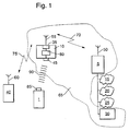
- FIG. 1 shows a block diagram of a radio system to which a terminal is connected with optical interface
- Figure 2 is a flowchart for the operation of the method according to the invention.
- 5 denotes a base station of, for example, a cordless telephone system.
- the cordless telephone system can be based, for example, the DECT standard.
- the radio system can also be a mobile radio system, for example, according to the GSM standard.
- a first transmitting / receiving antenna 50 is connected to the base station 5.
- the base station 5 spans a radio cell 65.
- a printer 30 may be connected, which is according to Figure 1 within the radio cell 65, but could also be located outside the radio cell 65.
- the printer 30 can be connected to the base station 5 at least a data or telecommunications network 15, 20, be connected 25th It can be a local or act a public network.
- the base station 5 is connected to an ISDN network 15 (Integrated Services Data Network), a local area network 20 and a trained as Internet data network 25.
- ISDN network 15 Integrated Services Data Network
- These subscribers can be arranged far outside the radio cell 65.
- an intermediate station 10 is arranged within the radio cell 65, but preferably in an edge region of the radio cell 65.
- the intermediate station 10 comprises a radio transmitting / receiving unit 35, to which a second transmitting / receiving antenna 55 is connected.
- a first radio connection 70 can thus be set up which, depending on the use of the underlying radio standard, can be a DECT radio connection, a GSM radio connection or the like.
- the DECT standard is used, so that the first radio link 70 is a DECT radio link.
- a second terminal 40 which may be formed as cordless phone, as a mobile phone, as a mobile device as a handheld radio, as a work radio or the like.
- the second terminal 40 should be designed as a cordless telephone according to the DECT standard.
- a third transmitting / receiving antenna 60 is connected to the second terminal 40.
- a second radio link 75 can be constructed, which is based on the DECT standard according to the described embodiment.
- the intermediate station 10 thus operates as a relay station in the described radio system and thereby increases the range of the base station 5.
- the second terminal 40 Since the second terminal 40 is outside the radio cell 65, it can not record a direct radio connection with the base station 5. However, it may be the second Establish radio connection 75 to the intermediate station 10.
- the intermediate station 10 sets up the first radio connection 70 to the base station 5 and forwards corresponding radio data signals between the second terminal 40 and the base station 5 in a transparent manner.
- the intermediate station 10 operates towards the second terminal 40 as a base station and towards the base station 5 as a terminal.
- a radio connection can be established in a corresponding manner by the base station 5 via the intermediate station 10 to the second terminal 40.
- the intermediate station 10 further comprises an interface 45 designed as an optical transmitter / receiver unit.
- the interface 45 can be designed, for example, to emit and receive optical signals in an infrared frequency range.
- the interface 45 may be designed, for example, according to the IrDA standard (Infrared Data Association).
- the radio transmission / reception unit 35 is connected to the interface 45.
- a first terminal 1 is arranged outside the radio cell 65.
- the first terminal 1 can also be arranged within the radio cell 65.
- the first terminal 1 comprises an optical transmitting / receiving unit 85.
- the optical transmitting / receiving unit 85 of the first terminal 1 can also emit and receive optical signals, for example in an infrared wavelength range.
- an optical connection 90 for optical data transmission can be established in this way.
- the conversion unit 80 By means of the conversion unit 80, a conversion between optical data signals and radio data signals can take place so that the first terminal 1 can also communicate with the base station 5.
- both between the first terminal 1 and a subscriber of one of the data or telecommunications networks 15, 20, 25 and the printer 30 and between the second terminal 40 and a subscriber of the data or telecommunications network 15, 20, 25 and the printer 30 data are exchanged.
- data can be transmitted from the first terminal 1 or from the second terminal 40 via the intermediate station 10 to the base station 5 and from there forwarded to a subscriber of one of the data or telecommunication networks 15, 20, 25 or the printer 30.
- any data output unit may be connected to the base station 5 and communicate in a corresponding manner with the first terminal 1 or the second terminal 40.
- a local database server, a domotic system, etc. may be connected to the base station 5 and communicate via the base station 5 and the intermediate station 10 with the first terminal 1 and / or the second terminal 40 in the manner described.
- a radio channel to the base station 5 is switched by the intermediate station 10, via which the data is transmitted from the first terminal 1 or from the second terminal 40 to the base station 5.
- the base station 5 can switch a radio channel to the intermediate station 10, via the data of a subscriber of one of the data or telecommunications networks 15, 20, 25 or other devices connected to the base station 5 to the intermediate station 10 for forwarding to the first terminal 1 and / or the second terminal 40 are transmitted.
- FIG. 2 shows a flowchart for an exemplary mode of operation of the method according to the invention.
- the intermediate station 10 checks whether there is a connection request from the first terminal 1. If this is the case, the process branches to a program point 105, otherwise it branches to a program point 125th A connection request originating from the first terminal 1 is communicated by the optical request signal of the intermediate station 10 emitted by the transmitting / receiving unit 85 of the first terminal 1, in the described embodiment in the infrared frequency range.
- the intermediate station 10 switches a radio channel to the base station 5.
- a waiting loop is traversed. Subsequently, branch back to program point 100.
- a branch is made to a program point 110.
- the intermediate station 10 checks whether optical data signals are received by the first terminal 1 in the interface 45. If this is the case, then the program branches to a point 115, otherwise it branches to a program point 130th
- converting unit 80 converts the optical data signals into radio data signals and causes the radio transmitting / receiving unit 35 to transmit the radio data signals to the base station 5.
- a program point 120 is branched.
- the intermediate station 10 checks whether the connection has been terminated. If this is the case, the program part is left, otherwise it is branched back to program point 110.
- the intermediate station 10 checks whether radio data signals have been received by the base station 5 in the radio transmission / reception unit 35 and whether these radio data signals are addressed to the first terminal 1. If this is the case, the program branches to a program point 135, otherwise the program branches to program point 120.
- the conversion unit 80 converts the radio data signals into optical data signals.
- the optical data signals are then emitted from the interface 45 to the first terminal 1 by means of the optical connection 90 in the form of an infrared connection in this exemplary embodiment. Subsequently, the program branches to point 120th
- a bidirectional optical data transmission between the intermediate station 10 and the first terminal 1 may also be provided unidirectional data transmission, depending on the direction of transmission then at the first terminal 1 only an optical transmitting device or only an optical receiving device is provided and the interface 45 only an optical Receiving device or an optical transmitting device must include. Accordingly, it is then to be provided at the intermediate station 10, only one radio unit and a radio receiver unit. In this case, however, between the second terminal 40 and the base station 5 is no data exchange is possible.
- the intermediate station 10 can in the typical applications of radio repeaters, such as DECT repeaters for large office space, factory buildings or the like in addition to the relay function for corresponding radios, such as DECT cordless telephones, a transition of terminals with optical interface in the corresponding radio system can be realized.
- radio repeaters such as DECT repeaters for large office space, factory buildings or the like
- relay function for corresponding radios such as DECT cordless telephones
Landscapes
- Engineering & Computer Science (AREA)
- Computer Networks & Wireless Communication (AREA)
- Signal Processing (AREA)
- Mobile Radio Communication Systems (AREA)
Claims (10)
- Procédé de transmission de données par une liaison sans fil entre un terminal (1) et une station de base (5) qui couvre une cellule radio (65),
caractérisé en ce qu'on transmet les données entre le terminal (1) et l'une des stations intermédiaires (10) prévue dans la cellule radio de la station de base (5) par transmission de signaux optiques eton transmet les données entre la station intermédiaire (10) et la station de base (5) par des signaux radio, de préférence selon le standard DECT (téléphone sans fil numérique), etles données reçues par la station de base (5) sont transmises dans un réseau de données ou de télécommunication (15, 20, 25) relié à la station de base (5),la station intermédiaire (10) ayant une interface radio par laquelle elle reçoit les signaux radio d'un second terminal (40) et rayonne les signaux radio qu'elle en dérive vers la station de base. - Procédé selon la revendication 1,
caractérisé en ce qu'
à la transmission de données par le terminal (1) vers la station de base (5), on convertit les signaux optiques de la station intermédiaire (10) en signaux radio. - Procédé selon la revendication 1 ou 2,
caractérisé en ce qu'
à la transmission des données de la station de base (5) au terminal (1), on convertit les signaux radio de la station intermédiaire (10) en signaux optiques. - Procédé selon les revendications 1, 2 ou 3,
caractérisé en ce que
dans le cas d'une requête de liaison du terminal (1), la station intermédiaire (10) commute un canal radio vers la station de base (5). - Procédé selon l'une des revendications précédentes,
caractérisé en ce que
les données reçues de la station de base (5) sont transmises à une unité de sortie (30) raccordée, notamment à une imprimante. - Station intermédiaire (10) comportant une unité d'émission et une unité de réception radio (35),
caractérisée en ce quela station intermédiaire (10) comporte une interface (45) pour une transmission de signaux de données optiques entre un premier terminal (1) et la station intermédiaire (10), notamment dans le domaine infrarouge,la station intermédiaire (10) effectue une conversion entre les signaux de données optiques et les signaux de données radio etles signaux de données radio sont transmis par l'unité d'émission et de réception radio (35) entre la station intermédiaire (10) et une station de base (5) qui transmet les données reçues vers un réseau de données ou de télécommunication, la station de base (5) couvrant une cellule radio (65) dans laquelle se trouve la station intermédiaire etle réseau de données ou de télécommunication est relié à la station de base, la station intermédiaire (10) ayant une interface radio qui reçoit les signaux radio d'un second terminal (40) et rayonne vers la station de base (5) des signaux radio qui en sont dérivés. - Station intermédiaire (10) selon la revendication 6,
caractérisée en ce que
l'interface (45) comporte une unité d'émission/réception optique fonctionnant notamment selon le standard (IrDA) (Association de Données par infrarouge). - Station intermédiaire (10) selon la revendication 6 ou 7,
caractérisée en ce que
la station intermédiaire (10) convertit les signaux de données optiques reçus par le premier terminal (1) en signaux de données radio qu'elle émet vers la station radio (5). - Station intermédiaire (10) selon les revendications 6, 7, 8,
caractérisée en ce que
la station intermédiaire (10) convertit les signaux de données radio reçus par la station de base (5) en signaux de données optiques qu'elle émet vers le premier terminal (10). - Station intermédiaire (10) selon l'une des revendications 6 à 9,
caractérisée en ce que
pour une requête de liaison venant du premier terminal (10) la station intermédiaire commute un canal radio, de préférence selon le standard DECT vers la station de base (5).
Applications Claiming Priority (2)
| Application Number | Priority Date | Filing Date | Title |
|---|---|---|---|
| DE1997151845 DE19751845A1 (de) | 1997-11-22 | 1997-11-22 | Verfahren zur drahtlosen Datenübertragung und Zwischenstation |
| DE19751845 | 1997-11-22 |
Publications (3)
| Publication Number | Publication Date |
|---|---|
| EP0948224A2 EP0948224A2 (fr) | 1999-10-06 |
| EP0948224A3 EP0948224A3 (fr) | 2000-05-24 |
| EP0948224B1 true EP0948224B1 (fr) | 2007-11-07 |
Family
ID=7849550
Family Applications (1)
| Application Number | Title | Priority Date | Filing Date |
|---|---|---|---|
| EP98114704A Revoked EP0948224B1 (fr) | 1997-11-22 | 1998-08-05 | Méthode pour la transmission de données "sans-fil" et station intermédiaire |
Country Status (2)
| Country | Link |
|---|---|
| EP (1) | EP0948224B1 (fr) |
| DE (2) | DE19751845A1 (fr) |
Families Citing this family (1)
| Publication number | Priority date | Publication date | Assignee | Title |
|---|---|---|---|---|
| DE102010005007A1 (de) * | 2010-01-19 | 2011-07-21 | Frieters, Oliver, 86316 | Steuerungs-Baukasten |
Family Cites Families (3)
| Publication number | Priority date | Publication date | Assignee | Title |
|---|---|---|---|---|
| KR890702353A (ko) * | 1987-11-13 | 1989-12-23 | 원본미기재 | 통신장치 |
| FI109496B (fi) * | 1992-08-18 | 2002-08-15 | Nokia Corp | Laitteisto ja menetelmä digitaalisen infrapunavälitteisen tiedonsiirron järjestämiseksi radiopuhelinlaitteen perusosan ja toisen laitteen välillä |
| GB2301987B (en) * | 1995-06-05 | 2000-01-12 | Nokia Mobile Phones Ltd | Radio telephone text transmission system |
-
1997
- 1997-11-22 DE DE1997151845 patent/DE19751845A1/de not_active Withdrawn
-
1998
- 1998-08-05 EP EP98114704A patent/EP0948224B1/fr not_active Revoked
- 1998-08-05 DE DE59814119T patent/DE59814119D1/de not_active Expired - Lifetime
Non-Patent Citations (1)
| Title |
|---|
| None * |
Also Published As
| Publication number | Publication date |
|---|---|
| DE19751845A1 (de) | 1999-05-27 |
| EP0948224A3 (fr) | 2000-05-24 |
| EP0948224A2 (fr) | 1999-10-06 |
| DE59814119D1 (de) | 2007-12-20 |
Similar Documents
| Publication | Publication Date | Title |
|---|---|---|
| DE69323942T2 (de) | Infrarotverbindung zwischen einem Sendeempfänger und einem externen Gerät | |
| DE4215096C2 (de) | System zur Kommunikation zwischen tragbaren Telefoneinheiten | |
| DE69120204T2 (de) | Mobiles Funkkommunikationssystem mit mobiler Basisstation und tragbares Gerät als Mobilstation | |
| DE69730493T2 (de) | Alternatives leitweglenkungssystem für mobiltelefongespräche | |
| EP0849965A1 (fr) | Téléphone sans fil | |
| DE4310230C2 (de) | Tragbares Teilnehmerendgerät für den Mobilfunk | |
| DE29915676U1 (de) | Erweiterungsvorrichtung für ein Mobiltelefon | |
| EP0932524A1 (fr) | Recepteur radio | |
| DE60037157T2 (de) | Multimode Mobiltelefongerät | |
| DE19547809A1 (de) | Mobilfunkgerät mit integriertem Faxgerät | |
| EP1044578B1 (fr) | Procede permettant de faire fonctionner un terminal de telecommunications et terminal de telecommunications | |
| EP1121784B1 (fr) | Station de base pour un systeme radio pour courtes distances, et systeme de communication de donnees | |
| EP0948224B1 (fr) | Méthode pour la transmission de données "sans-fil" et station intermédiaire | |
| DE10135023A1 (de) | Schnittstelle | |
| EP1137240A2 (fr) | Radiotéléphone | |
| DE10016622B4 (de) | Verfahren zum Steuern von Leistungsmerkmalen in einem Funknetz und Anordnungen zur Realisierung des Verfahrens | |
| DE29825268U1 (de) | Zwischenstation | |
| WO1996038988A1 (fr) | Systeme de telecommunication mobile universel | |
| DE19616239C2 (de) | Verfahren zum Anschluß von Basisstationen eines schnurlosen Kommunikationssystems an eine ISDN-Nebenstellenanlage | |
| DE19644562C1 (de) | Verfahren zum drahtlosen Austausch von Daten und Telekommunikationseinheit | |
| EP1319318B1 (fr) | Installation de telecommunication comprenant une station de base et au moins un element mobile ainsi qu'un repeteur intermediaire | |
| DE10109478A1 (de) | Vorrichtung zur Adaption von Mobilfunkendgeräten an Telekommunikationssysteme in Telekommunikationsnetzen | |
| DE10114950A1 (de) | Faxgerät mit SMS-Funtionalität | |
| DE19600961A1 (de) | Kabel-Fernseh-Verteilnetz mit wenigstens einem Koaxialkabelabschnitt und wenigstens einem Glasfaserkabelabschnitt und zusätzlichem Anschluß von Endgeräten eines Fernmeldenetzes | |
| DE29622893U1 (de) | Über ein digitales Funknetz betriebene Kommunikationsgeräte sowie das Funknetz für diese Geräte |
Legal Events
| Date | Code | Title | Description |
|---|---|---|---|
| PUAI | Public reference made under article 153(3) epc to a published international application that has entered the european phase |
Free format text: ORIGINAL CODE: 0009012 |
|
| AK | Designated contracting states |
Kind code of ref document: A2 Designated state(s): DE FR GB IT |
|
| AX | Request for extension of the european patent |
Free format text: AL;LT;LV;MK;RO;SI |
|
| PUAL | Search report despatched |
Free format text: ORIGINAL CODE: 0009013 |
|
| AK | Designated contracting states |
Kind code of ref document: A3 Designated state(s): AT BE CH CY DE DK ES FI FR GB GR IE IT LI LU MC NL PT SE |
|
| AX | Request for extension of the european patent |
Free format text: AL;LT;LV;MK;RO;SI |
|
| 17P | Request for examination filed |
Effective date: 20001124 |
|
| AKX | Designation fees paid |
Free format text: DE FR GB IT |
|
| 17Q | First examination report despatched |
Effective date: 20040318 |
|
| GRAP | Despatch of communication of intention to grant a patent |
Free format text: ORIGINAL CODE: EPIDOSNIGR1 |
|
| RAP1 | Party data changed (applicant data changed or rights of an application transferred) |
Owner name: IPCOM GMBH & CO. KG |
|
| GRAS | Grant fee paid |
Free format text: ORIGINAL CODE: EPIDOSNIGR3 |
|
| GRAA | (expected) grant |
Free format text: ORIGINAL CODE: 0009210 |
|
| AK | Designated contracting states |
Kind code of ref document: B1 Designated state(s): DE FR GB IT |
|
| REG | Reference to a national code |
Ref country code: GB Ref legal event code: FG4D Free format text: NOT ENGLISH |
|
| REF | Corresponds to: |
Ref document number: 59814119 Country of ref document: DE Date of ref document: 20071220 Kind code of ref document: P |
|
| GBT | Gb: translation of ep patent filed (gb section 77(6)(a)/1977) |
Effective date: 20080204 |
|
| PLBI | Opposition filed |
Free format text: ORIGINAL CODE: 0009260 |
|
| 26 | Opposition filed |
Opponent name: NOKIA CORPORATOIN Effective date: 20080312 |
|
| ET | Fr: translation filed | ||
| PLBI | Opposition filed |
Free format text: ORIGINAL CODE: 0009260 |
|
| PLAB | Opposition data, opponent's data or that of the opponent's representative modified |
Free format text: ORIGINAL CODE: 0009299OPPO |
|
| 26 | Opposition filed |
Opponent name: RESEARCH IN MOTION LIMITED Effective date: 20080807 Opponent name: NOKIA CORPORATOIN Effective date: 20080312 |
|
| PLAX | Notice of opposition and request to file observation + time limit sent |
Free format text: ORIGINAL CODE: EPIDOSNOBS2 |
|
| PLBB | Reply of patent proprietor to notice(s) of opposition received |
Free format text: ORIGINAL CODE: EPIDOSNOBS3 |
|
| PLAB | Opposition data, opponent's data or that of the opponent's representative modified |
Free format text: ORIGINAL CODE: 0009299OPPO |
|
| RDAF | Communication despatched that patent is revoked |
Free format text: ORIGINAL CODE: EPIDOSNREV1 |
|
| PLAB | Opposition data, opponent's data or that of the opponent's representative modified |
Free format text: ORIGINAL CODE: 0009299OPPO |
|
| R26 | Opposition filed (corrected) |
Opponent name: RESEARCH IN MOTION LIMITED Effective date: 20080807 Opponent name: NOKIA CORPORATION Effective date: 20080312 |
|
| APAH | Appeal reference modified |
Free format text: ORIGINAL CODE: EPIDOSCREFNO |
|
| APBM | Appeal reference recorded |
Free format text: ORIGINAL CODE: EPIDOSNREFNO |
|
| APBP | Date of receipt of notice of appeal recorded |
Free format text: ORIGINAL CODE: EPIDOSNNOA2O |
|
| APBQ | Date of receipt of statement of grounds of appeal recorded |
Free format text: ORIGINAL CODE: EPIDOSNNOA3O |
|
| PGFP | Annual fee paid to national office [announced via postgrant information from national office to epo] |
Ref country code: GB Payment date: 20110831 Year of fee payment: 14 Ref country code: DE Payment date: 20110831 Year of fee payment: 14 Ref country code: FR Payment date: 20110905 Year of fee payment: 14 |
|
| PGFP | Annual fee paid to national office [announced via postgrant information from national office to epo] |
Ref country code: IT Payment date: 20110824 Year of fee payment: 14 |
|
| REG | Reference to a national code |
Ref country code: DE Ref legal event code: R103 Ref document number: 59814119 Country of ref document: DE Ref country code: DE Ref legal event code: R064 Ref document number: 59814119 Country of ref document: DE |
|
| APBU | Appeal procedure closed |
Free format text: ORIGINAL CODE: EPIDOSNNOA9O |
|
| RDAG | Patent revoked |
Free format text: ORIGINAL CODE: 0009271 |
|
| STAA | Information on the status of an ep patent application or granted ep patent |
Free format text: STATUS: PATENT REVOKED |
|
| 27W | Patent revoked |
Effective date: 20120515 |
|
| GBPR | Gb: patent revoked under art. 102 of the ep convention designating the uk as contracting state |
Effective date: 20120515 |
|
| REG | Reference to a national code |
Ref country code: DE Ref legal event code: R107 Ref document number: 59814119 Country of ref document: DE Effective date: 20121011 |