EP0948240A2 - Appareil de cuisson - Google Patents
Appareil de cuisson Download PDFInfo
- Publication number
- EP0948240A2 EP0948240A2 EP99302326A EP99302326A EP0948240A2 EP 0948240 A2 EP0948240 A2 EP 0948240A2 EP 99302326 A EP99302326 A EP 99302326A EP 99302326 A EP99302326 A EP 99302326A EP 0948240 A2 EP0948240 A2 EP 0948240A2
- Authority
- EP
- European Patent Office
- Prior art keywords
- screen
- display
- cooking apparatus
- displayed
- touch panel
- Prior art date
- Legal status (The legal status is an assumption and is not a legal conclusion. Google has not performed a legal analysis and makes no representation as to the accuracy of the status listed.)
- Granted
Links
- 238000010411 cooking Methods 0.000 title claims abstract description 128
- 230000004044 response Effects 0.000 claims abstract description 5
- 238000013479 data entry Methods 0.000 claims description 22
- 238000003825 pressing Methods 0.000 claims description 22
- 239000000758 substrate Substances 0.000 claims description 12
- 238000004140 cleaning Methods 0.000 claims description 9
- 230000005764 inhibitory process Effects 0.000 claims description 9
- 230000006870 function Effects 0.000 claims description 8
- 238000003860 storage Methods 0.000 abstract description 13
- 238000010438 heat treatment Methods 0.000 description 40
- 235000014510 cooky Nutrition 0.000 description 21
- 239000004973 liquid crystal related substance Substances 0.000 description 21
- 238000010586 diagram Methods 0.000 description 12
- 239000011521 glass Substances 0.000 description 7
- 229920002799 BoPET Polymers 0.000 description 6
- 238000000034 method Methods 0.000 description 5
- 238000007664 blowing Methods 0.000 description 4
- 238000010257 thawing Methods 0.000 description 4
- 235000013305 food Nutrition 0.000 description 3
- 239000012528 membrane Substances 0.000 description 3
- 125000006850 spacer group Chemical group 0.000 description 3
- 241000287828 Gallus gallus Species 0.000 description 2
- 239000000853 adhesive Substances 0.000 description 2
- 230000001070 adhesive effect Effects 0.000 description 2
- 239000002390 adhesive tape Substances 0.000 description 2
- 239000006071 cream Substances 0.000 description 2
- 239000004615 ingredient Substances 0.000 description 2
- 239000000463 material Substances 0.000 description 2
- 229920000139 polyethylene terephthalate Polymers 0.000 description 2
- 239000005020 polyethylene terephthalate Substances 0.000 description 2
- 238000010792 warming Methods 0.000 description 2
- 240000007124 Brassica oleracea Species 0.000 description 1
- 235000003899 Brassica oleracea var acephala Nutrition 0.000 description 1
- 235000011301 Brassica oleracea var capitata Nutrition 0.000 description 1
- 235000001169 Brassica oleracea var oleracea Nutrition 0.000 description 1
- 244000060011 Cocos nucifera Species 0.000 description 1
- 235000013162 Cocos nucifera Nutrition 0.000 description 1
- 230000002950 deficient Effects 0.000 description 1
- 239000004744 fabric Substances 0.000 description 1
- 235000013611 frozen food Nutrition 0.000 description 1
- AMGQUBHHOARCQH-UHFFFAOYSA-N indium;oxotin Chemical compound [In].[Sn]=O AMGQUBHHOARCQH-UHFFFAOYSA-N 0.000 description 1
- 238000004519 manufacturing process Methods 0.000 description 1
- 239000011159 matrix material Substances 0.000 description 1
- 238000012544 monitoring process Methods 0.000 description 1
- 235000021110 pickles Nutrition 0.000 description 1
- -1 polyethylene terephthalate Polymers 0.000 description 1
- 230000002787 reinforcement Effects 0.000 description 1
- 235000013547 stew Nutrition 0.000 description 1
Images









Classifications
-
- H—ELECTRICITY
- H05—ELECTRIC TECHNIQUES NOT OTHERWISE PROVIDED FOR
- H05B—ELECTRIC HEATING; ELECTRIC LIGHT SOURCES NOT OTHERWISE PROVIDED FOR; CIRCUIT ARRANGEMENTS FOR ELECTRIC LIGHT SOURCES, IN GENERAL
- H05B6/00—Heating by electric, magnetic or electromagnetic fields
- H05B6/64—Heating using microwaves
- H05B6/6435—Aspects relating to the user interface of the microwave heating apparatus
-
- A—HUMAN NECESSITIES
- A47—FURNITURE; DOMESTIC ARTICLES OR APPLIANCES; COFFEE MILLS; SPICE MILLS; SUCTION CLEANERS IN GENERAL
- A47J—KITCHEN EQUIPMENT; COFFEE MILLS; SPICE MILLS; APPARATUS FOR MAKING BEVERAGES
- A47J36/00—Parts, details or accessories of cooking-vessels
- A47J36/32—Time-controlled igniting mechanisms or alarm devices
-
- F—MECHANICAL ENGINEERING; LIGHTING; HEATING; WEAPONS; BLASTING
- F24—HEATING; RANGES; VENTILATING
- F24C—DOMESTIC STOVES OR RANGES ; DETAILS OF DOMESTIC STOVES OR RANGES, OF GENERAL APPLICATION
- F24C7/00—Stoves or ranges heated by electric energy
- F24C7/08—Arrangement or mounting of control or safety devices
- F24C7/082—Arrangement or mounting of control or safety devices on ranges, e.g. control panels, illumination
- F24C7/085—Arrangement or mounting of control or safety devices on ranges, e.g. control panels, illumination on baking ovens
-
- F—MECHANICAL ENGINEERING; LIGHTING; HEATING; WEAPONS; BLASTING
- F24—HEATING; RANGES; VENTILATING
- F24C—DOMESTIC STOVES OR RANGES ; DETAILS OF DOMESTIC STOVES OR RANGES, OF GENERAL APPLICATION
- F24C7/00—Stoves or ranges heated by electric energy
- F24C7/08—Arrangement or mounting of control or safety devices
- F24C7/082—Arrangement or mounting of control or safety devices on ranges, e.g. control panels, illumination
- F24C7/086—Arrangement or mounting of control or safety devices on ranges, e.g. control panels, illumination touch control
Definitions
- the present invention relates to a cooking apparatus such as a microwave oven, and particularly to a cooking apparatus that allows cooking to be performed in a manner fit for the material or menu to be cooked in accordance with selections made on an operation panel.
- the cooking apparatus disclosed therein has an operation panel 108 as shown in Figs. 19 and 20, which are a front view and a sectional side view, respectively, thereof.
- a start key 129 for starting cooking
- a liquid crystal display 118 for displaying the conditions and progress of cooking
- a rotary encoder 111 on the operation panel 108 are arranged on the operation panel 108 .
- switch keys 128 that are individually operated to switch between manual and automatic cooking, to display recipes and a rough (high-level) grouping of cooking methods, and to perform other functions.
- the operation panel 108 incorporates a rechargeable battery (not shown) and has a charge lamp 131 for indicating the remaining battery capacity so that the cooking apparatus proper can be operated by remote control even when the operation panel 108 is detached therefrom.
- a desired item can be highlighted by rotating the rotary encoder 111 and then selected by pressing a set button 132. By repeating such selection, it is possible to switch from one screen to another to show various contents such as cooking guides and middle- and low-level groupings of cooking methods, and thereby select a suitable cooking cycle. An already selected item can be canceled by pressing a reset button 133.
- Japanese Laid-Open Patent Applications Nos. H10-47683, H10-47684, H10-47685, and H10-47686 disclose cooking apparatuses having an operation panel as shown in Fig. 21. On this operation panel 208 are arranged a start key 229 for starting cooking, a liquid crystal display 226 for displaying the conditions and progress of cooking, and switch keys 228 that are individually operated to display a high-level grouping of commonly used cooking methods on the liquid crystal display 226.
- a desired item can be selected by pressing the corresponding one of the selection keys 227.
- a cancellation key 219 for canceling an already selected item
- arrow keys 224 for switching to the previous and next screens, respectively.
- Japanese Laid-Open Patent Application No. S59-183220 discloses a cooking apparatus whose operation and display units incorporate a liquid crystal display device having transparent touch electrodes so that, when a portion of the screen displayed on the liquid crystal display is operated to select a desired operation, the selected operation is indicated by changing the state of that portion of the screen.
- An object of the present invention is to provide a user-friendly cooking apparatus that allows easy selection of a cooking menu or a cooking guide.
- a cooking apparatus which has display means (11) and selecting means (12) for selecting an item displayed on the display means (11) and in which the display means (11) displays one screen after another (71-73, 74a-74d) so as to correspond to one item after another selected thereon is provided with: a bookmark attachment requesting member (15) for requesting attachment of a bookmark to a specific screen (74c) displayed on the display means (11); a memory (90) for storing data related to the bookmarked screen; a bookmarked screen display requesting member(15) for requesting display of the bookmarked screen; and a display controller (88) for displaying the bookmarked screen (74c') in accordance with the data stored in the memory (90) in response to a request from the bookmarked screen display requesting member (15).
- a cooking apparatus which has display means (11) and selecting means (12) for selecting an item displayed on the display means (11) and in which the display means (11) displays one screen after another so as to correspond to one item after another selected thereon is provided with: an index key (16) for displaying, as items (79a) displayed on the display means (11), a list of names of groups into which cooking menus are classified by their first letter; and a display controller (88) for displaying a list (79c, 79d) of cooking menus belonging to a group selected by the selecting means (12).
- the data entry means (4) has data entry keys (4) that are individually operated and has a transparent touch panel (3) laid over the front surface of the display means (9) to allow cooking conditions to be entered by interactively switching the screens displayed on the display means (9) by operating the touch panel (3).
- the touch panel (3) is composed of: a transparent substrate (30) having a first transparent electrode (30a) formed on a surface; and a flexible transparent film (31) having a second transparent electrode (31a) formed on a surface.
- the transparent film (31) is laid over the transparent substrate (30) and bonded thereto at their edges, with an air layer (33) secured in between and with the first and second transparent electrodes (30a, 31a) facing each other.
- a connector for connecting one end of a key cable (7) whose other end is connected to a control circuit is provided in the touch panel (3), and an air passage (33a) is provided near the connector to allow air to flow freely into and out of the air layer (33).
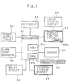
- Fig. 1 is a block diagram showing the control circuit of the cooking apparatus, such as a microwave oven, of a first embodiment of the invention.
- reference numeral 81 represents a microcomputer that has a temporary storage memory (RAM) 81a and that controls various operations, such as cooking, display, and data entry operations, performed in the cooking apparatus.
- RAM temporary storage memory
- a power supply circuit 82 Connected to the microcomputer 81 are a power supply circuit 82, a key circuit 83 for generating signals corresponding to the operation of the keys arranged on the operation panel 10 (see Fig. 2) described later, a sensor 84 for monitoring the temperature, humidity. and the like in the heating chamber (not shown), an alarm sound generator 85 for generating various alarm sounds in accordance with the operation status of the heating means such as a magnetron, a relay circuit 86 for switching the states of the driving circuit of the cooking apparatus, an external storage memory 87 having a large storage capacity, a display control circuit 88 for driving and controlling the liquid crystal display 89 provided on the operation panel 10, and a nonvolatile memory (EEPROM) 90 that allows data to be freely written thereto and erased therefrom.
- EEPROM nonvolatile memory
- liquid crystal display 89 a full-dot-matrix STN (supertwisted nematic) liquid crystal display panel is used to allow cooking-related messages and guides to be displayed in characters and with illustrations that are large enough to be easily recognizable.
- STN supertwisted nematic
- the external storage memory 87 is used to store display data, alarm sound data, and cooking data, as well as the programs executed by the microcomputer.
- the programs may be stored in a internal storage memory (ROM) 81d provided within the microcomputer 81.
- ROM internal storage memory
- the microcomputer 81 reads the display data of one screen by reading a fraction thereof at a time and repeating such a reading operation several times, storing the read fraction in the temporary storage memory 81a every time.
- the microcomputer 81 transfers the display data stored in the temporary storage memory 81a to a display memory 88a provided within the display control circuit 88.
- the display data stored in the display memory 88a is fed to the liquid crystal display 89 sequentially for one column of pixels after another in the form of a display data signal.
- Fig. 2 is a front view of the operation panel 10 of the cooking apparatus of this embodiment.
- the operation panel 10 has a display panel 11 composed of a liquid crystal display 89 as described above, and has four selection keys 12 arranged by the side of the display panel 11.
- the selection keys 12 are used to select an item, such as a cooking cycle, on a screen displayed on the display panel 11.
- a back key 13 for feeding backward the screens thus far displayed
- a next key 14 for feeding forward the screens thus far fed backward
- a bookmark key 15 for attaching a bookmark to the screen currently displayed
- an index key 16 for displaying a list of the names of the groups [A], [B], [C],... into which cooking menus are classified by their first letter.
- automatic cooking menu keys 17 for directly selecting a menu to be cooked, and four manual heating mode selection keys 18 for manually setting the heating mode.
- start key 19 for starting cooking
- cancel key 20 for canceling an already selected item
- heating time entry key 21 for manually entering the heating time and other values
- door open button 22 for opening the door of the cooking apparatus.
- the screens displayed on the display panel 11 to allow selection of a cooking menu have a hierarchical structure. Switching from one screen to another screen lower in level is achieved by pressing one of the selection keys 12.
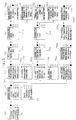
- Fig. 3 shows examples of such switching of screens.
- the selection screen 71 of the highest-level grouping of menus the following four items are displayed as alternatives for selection: [cooking] for selecting a listing of automatic menus, [warming] for selecting a listing of various modes of automatic warming by microwaves, [thawing] for selecting a listing of various modes of automatic thawing of frozen food, and [cooking guides] for selecting a listing of cooking-related messages and pieces of advice.
- the screen is switched to the selection screen 72, belonging to a one step lower level shown under (b), of a listing of groups of cooking menus for automatic cooking.
- the selection screen 72 of a listing of groups of cooking menus it is possible to switch from one page 72 of the screen to another 73 by pressing the next key 14 (see Fig. 2).
- the screen is switched to the selection screen 74f, belonging to the level (f), of a listing related to the recipe.
- the listing includes items [ingredients], [preparing dough], [forming], and [baking].
- the corresponding piece of recipe-related information is displayed on the screen.
- the screen is switched to the selection screen 75d, belonging to the level (e), for choosing between [baking] and [recipe].
- the screen is switched to the selection screen 75e. belonging to the level (f), for selecting how the cake is to be baked from among [brown], [standard], and [light].
- the start key 19 see Fig. 2 is pressed, heating is started.
- [standard] is selected.
- the screen is switched to the selection screen 75f, belonging to the level (f), of a listing related to the recipe.
- the screen is switched to the screen 76a, belonging to the level (c), of [hints on cooking] in which a listing is displayed including items [handy à-la-carte dishes], [dishes from all over the world], [dishes for children], and [notes on cooking].
- the screen is switched to the selection screen 76b, belonging to the level (d), of [notes on cooking].
- the screen is switched to the selection screen 76c, belonging to the level (e), of a listing related to [tips on frying].
- the bookmark key 15 serving as a bookmark attachment requesting member
- a screen with an indication symbol 77 is displayed, it is possible to attach a bookmark to that screen. This is achieved by storing the corresponding screen code in the nonvolatile memory 90 (see Fig. 1).
- a screen to which a bookmark is attached is referred to also as a "bookmarked" screen.
- Fig. 4 shows an example of how a bookmark is attached to a screen.
- the bookmark key 15 is pressed while the selection screen 74c of [cut-out cookies] as shown at (a) is displayed, the screen is switched to the screen 78a as shown at (b).
- the screen code of the set of display data for the screen [cut-out cookies] is stored in the nonvolatile memory 90.
- the screen is switched to the screen 78b as shown at (c), where the message "The screen 'cut-out cookies' stored” is displayed for a predetermined length of time. Thereafter, the screen is switched to the screen 74c' of [cut-out cookies] as shown at (d). In this screen, the indication symbol 77 is displayed in reverse video so that it will be easily recognizable that a bookmark is attached to this screen 74c'.
- Fig. 5 shows an example of how a bookmark is erased from a screen.
- the bookmark key 15 is held pressed for three seconds while the screen 74c' of [cut-out cookies] as shown at (a) is displayed, the screen is switched to the screen 78c as shown at (b).
- the same bookmark key 15 is used here as is used to attach the bookmark.
- the screen code of the set of display data for the screen [cut-out cookies] which has thus far been stored in the nonvolatile memory 90, is erased therefrom.
- the screen is switched back to the screen 74c as shown at (a) in Fig. 4, with the indication symbol 77, which has thus far been displayed in reverse video, now displayed in normal video.
- bookmark key 15 serving as a bookmarked screen display requesting member
- the initial screen belonging to the level (a) shown in Fig. 3, that is displayed in the stand-by state, or one of the screens, belonging to the level (b), that do not have an indication symbol 77 is displayed
- a listing is displayed on which the titles of the screens thus far bookmarked are listed in chronological order (with the most recently bookmarked one displayed at the top). By selecting the title of the desired screen on this listing, it is possible to jump to and display that screen.
- the display data is divided into the data of the title portion and the data of the remaining portion. Then, the display data is stored in the nonvolatile memory 90 with one screen code for the title portion and with another screen code having a different last digit for the remaining portion. This makes it easier to retrieve a screen code when a specific screen is displayed, and to distinguish a case where an entire screen is displayed from a case where a list of the titles of screens is displayed.
- two sets of data are previously stored in the internal storage memory 81d or in the external storage memory 87.
- the display program first checks whether the screen is bookmarked or not, and then reads the appropriate one of the two sets of data to display it on the screen. This helps simplify the program.
- the selection screen 79c as shown at (c) is displayed on which the first page, including the items [cabbage pickles], [chicken cutlet], [chicken sauté], and [coconut cookies], of a listing of cooking menus starting with the letter C arranged in alphabetical order is shown.
- the next key 14 the next page of the listing as shown at (d), including the items [cream buns], [cream stew], [croquette], and [cut-out cookies], is displayed.
- the screen is switched to the screen of that cooking menu. For example, when [cut-out cookies] is selected, the selection screen 74c of [cut-out cookies] as shown in Fig. 3 is displayed, and thereafter it is possible to continue operation in the same way as described earlier.
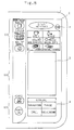
- Figs. 8 and 9 are a front view and a sectional side view of the operation panel of the cooking apparatus of a second embodiment of the invention.
- the operation panel 1 is divided into an upper portion G1, a middle portion G2, and a lower portion G3, and the upper and lower portions G1 and G3 are provided with individually operated entry keys 4 formed on a print sheet 2 by printing.
- These entry keys 4 are assigned frequently used functions, and, to make their functions easily recognizable, they are marked with, for example, characters or a symbol representing a type of food or a piece of tableware.
- the print sheet 2 has, in its middle portion G2, a touch panel 3.
- the touch panel 3 has, on its back surface, a display panel 9 (see Fig. 9) such as a liquid crystal display or fluorescent display tube for displaying the current time and a plurality of alternatives as to the heating mode and heating pattern to allow heating to be performed in a manner fit for the material or menu to be cooked.
- a printed circuit board 5 on which a microcomputer 6, a key cable 7, and a control circuit 8 are provided.
- the key cable 7 connects the touch panel 3 to the circuitry formed on the printed circuit board 5 to achieve control of input/output operations of the touch panel 3.
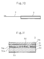
- Figs. 10 and 11 show the structure of the touch panel 3, with Fig. 10 showing a side view thereof and Fig. 11 showing a sectional side view of the principal portion thereof.
- a flexible PET (polyethylene terephthalate) film 31 is laid on a glass substrate (transparent substrate) 30.
- the PET film 31 is bonded to the glass substrate 30 with double-sided adhesive tape 34 applied along their edges, with an air layer 33 secured between them.
- a transparent conductive pattern 31a (a second transparent electrode) made of ITO (indium tin oxide) is formed.
- a transparent conductive pattern 30a (a first transparent electrode) made of ITO is formed.
- hemispheric spacers 32 are formed to keep uniform the thickness of the space secured between the conductive patterns 31a and 30a (this space will hereafter be referred to as the "membrane gap").
- the entry keys 4 formed in the upper and lower portions G1 and G3 of the print sheet 2 have tact switches 4a (see Fig. 9) or the like arranged on their back surface so that they are operated with a comparatively strong pressing force. This helps change the operation feel according to what is going to be entered, and thereby enhance the user-friendliness.
- the tact switches 4a it is possible to use membrane keys composed of printed spacer sheets. Moreover, the tact switches 4a do not necessarily have to be mounted on the printed circuit board 5.
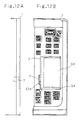
- Figs. 12A and 12B show how the operation panel 1 and the touch panel 3 are fitted, with Fig. 12A showing a side view thereof and Fig. 12B showing a front view thereof.
- Fig. 13 is an exploded perspective view showing how the touch panel 3 is fitted to the operation panel 1.
- the touch panel 3 has already been assembled in the preceding process from a plurality of touch panel components K including the glass substrate 30.
- a plurality of strip-shaped conductive patterns 30a each having a width L are formed on the glass substrate 30 by printing, and, perpendicularly thereto, a plurality of strip-shaped conductive patterns 31a having a width W are formed on the PET film 31 by printing.
- the PET film 31 has a reinforcement film 31b laid over its top surface.
- a part of the double-sided adhesive tape 34 that is used to fix the PET film 31 to the glass substrate 33 together is cut away so as to form an air passage 33a.
- the touch panel 3 is fitted, with an adhesive or the like, into a recess 1b that is so formed as to be deeper than the pressing surface 1a of the entry keys by the thickness of the touch panel 3.
- This recess 1b permits the touch panel 3 to be fixed accurately in position.
- the display panel 9 such as a liquid crystal display or fluorescent display tube and the touch panel 3 are held together.
- the key cable 7 is placed to achieve connection to a control circuit 8 (see Fig. 9).
- the air passage 33a communicates with the space behind the operation panel 1 so that air can flow freely into and out of the air layer 33. This helps keep uniform the pressing force required to operate the touch panel 3.
- an adhesive is applied to the back surface of the print sheet 2 except within the areas 2a and 2b enclosed by broken lines so that the print sheet 2 can be fitted over the operation panel 1.
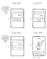
- Figs. 14A to 14H show an example of how one screen after another is displayed as the touch panel 3 is operated.
- the "OVEN/LEAVENING" key which is one of the individually operated entry keys 4
- alternatives of the heating mode are displayed on the touch panel 3.
- the touch panel 3 has its surface divided into an active area and an inactive area, and when an operation is performed within a boundary figure 43 provided within the active area, the screen is switched to the next one.
- the active area is so assigned as to include two boundary figures, one for requesting preheating (the "preheating yes” key 43a) and the other for rejecting preheating (the "no” key 43b), so as to allow choice between two alternatives.
- the screen is switched to the screen shown in Fig. 14B.
- a heating mode is selected from among heating by hot air circulation, heating with the heaters provided at the top and at the bottom of the heating chamber, and heating by microwaves.
- the active area is so assigned as to include the following four boundary figures 43c to allow selection from four alternatives: “hot blowing" for heating by hot air circulation, “heat from above & below” for heating with the heaters from both above and below, “intenser heat from above” for heating with intenser heat from above, and “intenser heat from below” for heating with intenser heat from below.
- the screen is switched to the screen shown in Fig. 14C.
- heating conditions are set.
- the initial value (180 °C) for the heating temperature is displayed in a temperature display area 43f
- the initial value (20 minutes) for the heating time is displayed in a heating time display area 43g.
- heating temperature adjustment keys 43d and heating time adjustment keys 43e are displayed, to which the active area is assigned.
- the message "preheating ready” is displayed on the touch panel 3 as shown in Fig. 14F.
- the heating chamber is kept preheated.
- the "START HEATING" key is pressed with food put in the heating chamber, cooking is started.
- indications are displayed which indicate that cooking is in progress in the "oven hot blowing" mode with the heating temperature set for "180°C” and the heating time set for "25 min. (minutes) 00 sec. (seconds)" as shown in Fig. 14G.
- Fig. 15 shows the positional relationship between the active and inactive areas on the touch panel 3.
- the active area on the touch panel 3 is divided into regions 51 to 62 with the inactive area filling the gap between two adjacent regions so as to prevent simultaneous selection of more than one region.
- a boundary figure 43 is so provided as to cover one or more of these regions, and the regions other than those assigned to a boundary figure 43 are treated as belonging to the inactive area by ignoring an operation made therein. This permits input operations to be performed without errors.
- the character-based data items, symbols, and illustrations displayed on the display panel 9 can be operated interactively by directly operating the touch panel 3.
- the active and inactive areas can be assigned differently on different screens, and a boundary figure 43 can be freely assigned to cover a part of the active area. This helps make clear where an input operation is accepted on the touch panel 3, and thereby prevent omission and errors in input operations.
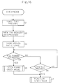
- Fig. 16 is a flow chart showing an example of the flow of operations performed to check the operation of the operation panel 1 in the manufacturing process.
- steps S1, S2, S3, and S4 when the "GRILL” and “HEALTHY MENUS” keys (see Fig. 8) on the print sheet 2 are pressed, and then the door of the heating chamber is opened and then closed, and then the "FULL THAWING" key is pressed, the microcomputer 6, through the printed circuit board 5, recognizes this flow of operations and starts a mode for checking the touch panel 3 (steps S4 and S5).
- step S7 a function check mode for checking the input/output status of other keys is started.
- step S4 If, in step S4, the "FULL THAWING" key is not pressed and instead the "SAKE” key is pressed, the microcomputer 6, through the printed circuit board 5, recognizes this flow of operations (step S6) and starts the function check mode (step S7).
- the touch panel check mode for checking the touch panel 3 and the display panel 9 can be started by simple key operation. This helps enhance productivity. Moreover, the function check mode makes it possible to detect defective assembly of the operation panel 1 and of the control circuit board. Note that the number of items from which selection is allowed on the touch panel 3 is not limited to any specific number used in the embodiment described above.
Landscapes
- Engineering & Computer Science (AREA)
- Chemical & Material Sciences (AREA)
- Combustion & Propulsion (AREA)
- Mechanical Engineering (AREA)
- General Engineering & Computer Science (AREA)
- Food Science & Technology (AREA)
- Human Computer Interaction (AREA)
- Physics & Mathematics (AREA)
- Electromagnetism (AREA)
- Electric Ovens (AREA)
- Information Retrieval, Db Structures And Fs Structures Therefor (AREA)
Applications Claiming Priority (4)
| Application Number | Priority Date | Filing Date | Title |
|---|---|---|---|
| JP8371298A JP3597987B2 (ja) | 1998-03-30 | 1998-03-30 | 加熱調理器 |
| JP8371298 | 1998-03-30 | ||
| JP10232944A JP2000065360A (ja) | 1998-08-19 | 1998-08-19 | 調理装置 |
| JP23294498 | 1998-08-19 |
Publications (3)
| Publication Number | Publication Date |
|---|---|
| EP0948240A2 true EP0948240A2 (fr) | 1999-10-06 |
| EP0948240A3 EP0948240A3 (fr) | 2000-04-12 |
| EP0948240B1 EP0948240B1 (fr) | 2004-08-25 |
Family
ID=26424743
Family Applications (1)
| Application Number | Title | Priority Date | Filing Date |
|---|---|---|---|
| EP99302326A Expired - Lifetime EP0948240B1 (fr) | 1998-03-30 | 1999-03-25 | Appareil de cuisson |
Country Status (3)
| Country | Link |
|---|---|
| US (1) | US6097016A (fr) |
| EP (1) | EP0948240B1 (fr) |
| DE (1) | DE69919619T2 (fr) |
Cited By (3)
| Publication number | Priority date | Publication date | Assignee | Title |
|---|---|---|---|---|
| EP1274283A3 (fr) * | 2001-07-02 | 2005-06-22 | Lg Electronics Inc. | Dispositif et méthode de commande de visualisation de menus dans un four à micro-ondes |
| DE19834230B4 (de) * | 1998-07-29 | 2016-08-18 | BSH Hausgeräte GmbH | Verfahren und Vorrichtung zum Einstellen eines Betriebsprogramms eines programmgesteuerten Haushaltgeräts |
| US10996820B2 (en) | 2017-12-29 | 2021-05-04 | Frima International Ag | Method for displaying an operating menu and activating a cooking appliance |
Families Citing this family (53)
| Publication number | Priority date | Publication date | Assignee | Title |
|---|---|---|---|---|
| KR100631192B1 (ko) * | 1999-08-19 | 2006-10-04 | 삼성전자주식회사 | 전자렌지 및 그 제어방법 |
| US6486453B1 (en) * | 1999-09-13 | 2002-11-26 | Maytag Corporation | Menu driven control system for a cooking appliance |
| US6809301B1 (en) * | 2000-06-30 | 2004-10-26 | General Electric Company | Oven control method and apparatus |
| JP2002022176A (ja) | 2000-07-12 | 2002-01-23 | Sharp Corp | 電子レンジ |
| US7065714B1 (en) * | 2000-10-13 | 2006-06-20 | Oracle International Corporation | Graphical user interface for navigation, viewing and maintenance of recipes |
| EP1351161A4 (fr) * | 2001-05-30 | 2004-04-14 | Matsushita Electric Industrial Co Ltd | Terminal, serveur, procede de stockage de donnees et programme d'execution dudit procede |
| US20020190057A1 (en) * | 2001-06-19 | 2002-12-19 | Bsh Home Appliances Corporation | Cooktop control |
| US6624390B1 (en) * | 2001-07-20 | 2003-09-23 | Cape Simulations, Inc. | Substantially-uniform-temperature annealing |
| US6750433B2 (en) * | 2001-11-29 | 2004-06-15 | General Electric Company | Oven display and user interface |
| KR100476451B1 (ko) * | 2002-02-14 | 2005-03-17 | 엘지전자 주식회사 | 전자레인지의 메뉴선택장치 |
| FR2842888B1 (fr) * | 2002-07-26 | 2004-09-03 | Thirode Grandes Cuisines Poligny | Systeme de commande de four |
| KR20040017188A (ko) * | 2002-08-20 | 2004-02-26 | 삼성전자주식회사 | 히터를 구비한 조리기 |
| KR100519264B1 (ko) * | 2002-08-29 | 2005-10-07 | 삼성전자주식회사 | 전자렌지 및 그 제어방법 |
| KR20040059142A (ko) * | 2002-12-28 | 2004-07-05 | 삼성전자주식회사 | 전자레인지 및 그 제어 방법 |
| KR20040067641A (ko) * | 2003-01-24 | 2004-07-30 | 삼성전자주식회사 | 전자렌지 |
| JP2004278922A (ja) * | 2003-03-17 | 2004-10-07 | Matsushita Electric Ind Co Ltd | 加熱調理装置 |
| US6933477B2 (en) | 2003-04-10 | 2005-08-23 | Maytag Corporation | Menu driven control system for a cooking appliance |
| DE10342531B4 (de) * | 2003-09-12 | 2014-09-11 | BSH Bosch und Siemens Hausgeräte GmbH | Steuerung für ein Haushaltgerät |
| DE10342321A1 (de) * | 2003-09-12 | 2005-04-07 | BSH Bosch und Siemens Hausgeräte GmbH | Steuerung für ein Haushaltgerät und Anzeige von Informationen |
| US7335858B2 (en) * | 2003-12-18 | 2008-02-26 | Applica Consumer Products, Inc. | Toaster using infrared heating for reduced toasting time |
| US20050218139A1 (en) * | 2004-03-31 | 2005-10-06 | Hp Intellectual Corporation | Intelligent user interface for new cooking technologies |
| US7619186B2 (en) * | 2004-02-10 | 2009-11-17 | Applica Consumer Products, Inc. | Intelligent user interface for multi-purpose oven using infrared heating for reduced cooking time |
| US7323663B2 (en) | 2004-02-10 | 2008-01-29 | Applica Consumer Products, Inc. | Multi-purpose oven using infrared heating for reduced cooking time |
| EP1742555A4 (fr) * | 2004-04-30 | 2010-03-24 | Salton | Appareil de cuisson electrique a plaques chauffantes amovibles et procede d'utilisation associe |
| US7069090B2 (en) * | 2004-08-02 | 2006-06-27 | E.G.O. North America, Inc. | Systems and methods for providing variable output feedback to a user of a household appliance |
| DE102004046521B3 (de) * | 2004-09-23 | 2006-04-20 | Rational Ag | Verfahren zum Einstellen oder Auswählen eines Arbeitsprogrammes eines Gargeräts und Gargerät zum Durchführen solch eines Verfahrens |
| US9057526B2 (en) * | 2004-09-30 | 2015-06-16 | Whirlpool Corporation | Programmable cooking appliance |
| US8005780B2 (en) * | 2005-06-09 | 2011-08-23 | Whirlpool Corporation | Taxonomy engine and dataset for operating an appliance |
| EP2228969B1 (fr) * | 2005-06-09 | 2017-04-19 | Whirlpool Corporation | Système d'architecture logicielle et procédé de communication correspondant, et gestion d'au moins un composant dans un appareil domestique |
| US20090078696A1 (en) * | 2006-01-26 | 2009-03-26 | Kyung-Jin Kim | Method of controlling cooker |
| DE102007040651B4 (de) * | 2007-08-27 | 2012-02-09 | Rational Ag | Verfahren zur Einstellung eines Garprogramms über visualisierte Gargutparameter und Gargerät hierfür |
| DE102008027220A1 (de) * | 2008-06-02 | 2009-12-03 | E.G.O. Elektro-Gerätebau GmbH | Anzeigevorrichtung für ein Kochfeld, Kochfeld und Verfahren zum Betrieb einer solchen Anzeigevorrichtung |
| DE102008032451C5 (de) * | 2008-07-10 | 2017-10-19 | Rational Ag | Anzeigeverfahren und Gargerät hierfür |
| DE102009000652A1 (de) * | 2009-02-06 | 2010-08-12 | BSH Bosch und Siemens Hausgeräte GmbH | Portable medienfähige Konsole |
| EP2486329A1 (fr) * | 2009-10-09 | 2012-08-15 | Electrolux Home Products, Inc. | Système d'interface d'appareil |
| DE102010063186A1 (de) * | 2010-12-16 | 2012-06-21 | BSH Bosch und Siemens Hausgeräte GmbH | Bedienvorrichtung für ein Hausgerät mit einem elektronischen Anzeigefeld |
| USD771568S1 (en) | 2015-03-06 | 2016-11-15 | Hamilton Beach Brands, Inc. | Jack receiver with cover |
| USD777105S1 (en) | 2015-03-06 | 2017-01-24 | Hamilton Beach Brands, Inc. | Jack receiver with cover |
| US9474413B2 (en) | 2015-03-06 | 2016-10-25 | Hamilton Beach Brands, Inc. | Kitchen appliance with an improved temperature probe jack receiver cover |
| EP3115697A1 (fr) * | 2015-07-10 | 2017-01-11 | Electrolux Appliances Aktiebolag | Unité de commande pour un appareil ménager |
| DE202018006410U1 (de) | 2017-08-09 | 2020-04-23 | Sharkninja Operating Llc | Kochgerät und Komponenten davon |
| USD914447S1 (en) | 2018-06-19 | 2021-03-30 | Sharkninja Operating Llc | Air diffuser |
| USD903413S1 (en) | 2018-08-09 | 2020-12-01 | Sharkninja Operating Llc | Cooking basket |
| USD883014S1 (en) | 2018-08-09 | 2020-05-05 | Sharkninja Operating Llc | Food preparation device |
| USD934027S1 (en) | 2018-08-09 | 2021-10-26 | Sharkninja Operating Llc | Reversible cooking rack |
| USD883015S1 (en) | 2018-08-09 | 2020-05-05 | Sharkninja Operating Llc | Food preparation device and parts thereof |
| US20190254476A1 (en) | 2019-02-25 | 2019-08-22 | Sharkninja Operating Llc | Cooking device and components thereof |
| WO2020176477A1 (fr) | 2019-02-25 | 2020-09-03 | Sharkninja Operating Llc | Système de cuisson avec protection |
| USD982375S1 (en) | 2019-06-06 | 2023-04-04 | Sharkninja Operating Llc | Food preparation device |
| USD918654S1 (en) | 2019-06-06 | 2021-05-11 | Sharkninja Operating Llc | Grill plate |
| KR102836706B1 (ko) * | 2019-08-13 | 2025-07-18 | 엘지전자 주식회사 | 블렌더 |
| US10912411B1 (en) * | 2019-10-03 | 2021-02-09 | Travis Twining | Roller cooker |
| US11647861B2 (en) | 2020-03-30 | 2023-05-16 | Sharkninja Operating Llc | Cooking device and components thereof |
Citations (6)
| Publication number | Priority date | Publication date | Assignee | Title |
|---|---|---|---|---|
| JPS59183220A (ja) | 1983-04-01 | 1984-10-18 | Matsushita Electric Ind Co Ltd | 加熱装置 |
| JPH0917156A (ja) | 1995-06-28 | 1997-01-17 | Aiwa Co Ltd | ディスクプレーヤ |
| JPH1047684A (ja) | 1996-07-29 | 1998-02-20 | Sharp Corp | 調理装置 |
| JPH1047686A (ja) | 1996-07-29 | 1998-02-20 | Sharp Corp | 調理装置 |
| JPH1047683A (ja) | 1996-07-29 | 1998-02-20 | Sharp Corp | 調理装置 |
| JPH1047685A (ja) | 1996-07-29 | 1998-02-20 | Sharp Corp | 調理装置 |
Family Cites Families (15)
| Publication number | Priority date | Publication date | Assignee | Title |
|---|---|---|---|---|
| US4035195A (en) * | 1975-08-11 | 1977-07-12 | Hercules Incorporated | Crosslinking cellulose polymers |
| JPS592802B2 (ja) * | 1978-09-25 | 1984-01-20 | シャープ株式会社 | 加熱調理器 |
| US4447692A (en) * | 1981-05-18 | 1984-05-08 | Essex Group, Inc. | Control system with interactive display |
| US4628351A (en) * | 1984-04-23 | 1986-12-09 | Samsung Electronics Co., Ltd. | Cooking apparatus with a video display |
| US4841125A (en) * | 1985-07-18 | 1989-06-20 | Sharp Kabushiki Kaisha | Control unit for a heating system with memory means |
| JP2680716B2 (ja) * | 1990-04-26 | 1997-11-19 | シャープ株式会社 | 電子レンジ |
| JP2589592B2 (ja) * | 1990-10-22 | 1997-03-12 | シャープ株式会社 | 電子レンジ |
| KR950004808B1 (ko) * | 1991-12-21 | 1995-05-10 | 주식회사금성사 | 전자레인지의 자동 요리 제어장치 |
| AU6018494A (en) * | 1993-05-21 | 1994-12-20 | Arthur D. Little Enterprises, Inc. | User-configurable control device |
| US5704277A (en) * | 1994-11-29 | 1998-01-06 | Yung; Simon K. C. | Breadmaker and a coding system therefor |
| JP3363283B2 (ja) * | 1995-03-23 | 2003-01-08 | 株式会社日立製作所 | 入力装置、入力方法、情報処理システムおよび入力情報の管理方法 |
| JPH09318074A (ja) * | 1996-05-30 | 1997-12-12 | Sanyo Electric Co Ltd | 調理器 |
| TW339399B (en) * | 1996-07-10 | 1998-09-01 | Sharp Kk | Cooking apparatus sequentially displaying cooking methods on its display and cooking methods using such cooking apparatus |
| US5818446A (en) * | 1996-11-18 | 1998-10-06 | International Business Machines Corporation | System for changing user interfaces based on display data content |
| JPH11171656A (ja) * | 1997-12-05 | 1999-06-29 | Toshiba Ceramics Co Ltd | 浸漬ランス用キャスタブル耐火物 |
-
1999
- 1999-03-25 EP EP99302326A patent/EP0948240B1/fr not_active Expired - Lifetime
- 1999-03-25 DE DE69919619T patent/DE69919619T2/de not_active Expired - Lifetime
- 1999-03-30 US US09/281,002 patent/US6097016A/en not_active Expired - Lifetime
Patent Citations (6)
| Publication number | Priority date | Publication date | Assignee | Title |
|---|---|---|---|---|
| JPS59183220A (ja) | 1983-04-01 | 1984-10-18 | Matsushita Electric Ind Co Ltd | 加熱装置 |
| JPH0917156A (ja) | 1995-06-28 | 1997-01-17 | Aiwa Co Ltd | ディスクプレーヤ |
| JPH1047684A (ja) | 1996-07-29 | 1998-02-20 | Sharp Corp | 調理装置 |
| JPH1047686A (ja) | 1996-07-29 | 1998-02-20 | Sharp Corp | 調理装置 |
| JPH1047683A (ja) | 1996-07-29 | 1998-02-20 | Sharp Corp | 調理装置 |
| JPH1047685A (ja) | 1996-07-29 | 1998-02-20 | Sharp Corp | 調理装置 |
Cited By (3)
| Publication number | Priority date | Publication date | Assignee | Title |
|---|---|---|---|---|
| DE19834230B4 (de) * | 1998-07-29 | 2016-08-18 | BSH Hausgeräte GmbH | Verfahren und Vorrichtung zum Einstellen eines Betriebsprogramms eines programmgesteuerten Haushaltgeräts |
| EP1274283A3 (fr) * | 2001-07-02 | 2005-06-22 | Lg Electronics Inc. | Dispositif et méthode de commande de visualisation de menus dans un four à micro-ondes |
| US10996820B2 (en) | 2017-12-29 | 2021-05-04 | Frima International Ag | Method for displaying an operating menu and activating a cooking appliance |
Also Published As
| Publication number | Publication date |
|---|---|
| DE69919619T2 (de) | 2005-09-08 |
| DE69919619D1 (de) | 2004-09-30 |
| EP0948240A3 (fr) | 2000-04-12 |
| EP0948240B1 (fr) | 2004-08-25 |
| US6097016A (en) | 2000-08-01 |
Similar Documents
| Publication | Publication Date | Title |
|---|---|---|
| EP0948240B1 (fr) | Appareil de cuisson | |
| EP0482578B1 (fr) | Four à micro-ondes | |
| KR920009584B1 (ko) | 전자렌지 | |
| KR950001468B1 (ko) | 메모리에 기억된 조리프로그램에 따라 작동되는 마이크로 컴퓨터를 가지는 전자오븐 | |
| CA2181842C (fr) | Minuterie de rechauffement pour four | |
| JPH1147346A (ja) | スロットマシン | |
| GB2160694A (en) | Cooking apparatus | |
| JP3636648B2 (ja) | 調理器 | |
| WO2008037355A1 (fr) | Appareil de cuisson | |
| JP2000065360A (ja) | 調理装置 | |
| JPH11281064A (ja) | 加熱調理器 | |
| EP0688148A1 (fr) | Four à micro-ondes à dispositif de chauffage du fond | |
| EP0852318A1 (fr) | Module de commande, appareil de cuisson utilisant ce module et procede de mise en uvre | |
| JPH0616738B2 (ja) | 調理器の時刻設定方法 | |
| EP0251670B1 (fr) | Dispositif de contrôle pour appareils de cuisson | |
| JP3640770B2 (ja) | 加熱調理器 | |
| JP2860115B2 (ja) | 高周波加熱装置 | |
| JPH0140248B2 (fr) | ||
| JPH0122542B2 (fr) | ||
| JPS60105832A (ja) | 加熱調理器 | |
| JP3256097B2 (ja) | クレーム解析手段を備えた加熱調理器 | |
| JPH0126452B2 (fr) | ||
| JPS6196337A (ja) | 加熱調理装置 | |
| JPH10295553A (ja) | 製パン機 | |
| KR20060119513A (ko) | 가스오븐레인지의 조리모드 표시방법 |
Legal Events
| Date | Code | Title | Description |
|---|---|---|---|
| PUAI | Public reference made under article 153(3) epc to a published international application that has entered the european phase |
Free format text: ORIGINAL CODE: 0009012 |
|
| AK | Designated contracting states |
Kind code of ref document: A2 Designated state(s): DE FR GB |
|
| AX | Request for extension of the european patent |
Free format text: AL;LT;LV;MK;RO;SI |
|
| PUAL | Search report despatched |
Free format text: ORIGINAL CODE: 0009013 |
|
| AK | Designated contracting states |
Kind code of ref document: A3 Designated state(s): AT BE CH CY DE DK ES FI FR GB GR IE IT LI LU MC NL PT SE |
|
| AX | Request for extension of the european patent |
Free format text: AL;LT;LV;MK;RO;SI |
|
| 17P | Request for examination filed |
Effective date: 20000628 |
|
| AKX | Designation fees paid |
Free format text: AT BE CH LI |
|
| RBV | Designated contracting states (corrected) |
Designated state(s): DE FR GB |
|
| REG | Reference to a national code |
Ref country code: DE Ref legal event code: 8566 |
|
| 17Q | First examination report despatched |
Effective date: 20030724 |
|
| GRAP | Despatch of communication of intention to grant a patent |
Free format text: ORIGINAL CODE: EPIDOSNIGR1 |
|
| GRAS | Grant fee paid |
Free format text: ORIGINAL CODE: EPIDOSNIGR3 |
|
| GRAA | (expected) grant |
Free format text: ORIGINAL CODE: 0009210 |
|
| AK | Designated contracting states |
Kind code of ref document: B1 Designated state(s): DE FR GB |
|
| REG | Reference to a national code |
Ref country code: GB Ref legal event code: FG4D |
|
| REF | Corresponds to: |
Ref document number: 69919619 Country of ref document: DE Date of ref document: 20040930 Kind code of ref document: P |
|
| PLBE | No opposition filed within time limit |
Free format text: ORIGINAL CODE: 0009261 |
|
| STAA | Information on the status of an ep patent application or granted ep patent |
Free format text: STATUS: NO OPPOSITION FILED WITHIN TIME LIMIT |
|
| ET | Fr: translation filed | ||
| 26N | No opposition filed |
Effective date: 20050526 |
|
| PGFP | Annual fee paid to national office [announced via postgrant information from national office to epo] |
Ref country code: DE Payment date: 20130320 Year of fee payment: 15 Ref country code: FR Payment date: 20130325 Year of fee payment: 15 Ref country code: GB Payment date: 20130320 Year of fee payment: 15 |
|
| REG | Reference to a national code |
Ref country code: DE Ref legal event code: R119 Ref document number: 69919619 Country of ref document: DE |
|
| GBPC | Gb: european patent ceased through non-payment of renewal fee |
Effective date: 20140325 |
|
| REG | Reference to a national code |
Ref country code: FR Ref legal event code: ST Effective date: 20141128 |
|
| REG | Reference to a national code |
Ref country code: DE Ref legal event code: R119 Ref document number: 69919619 Country of ref document: DE Effective date: 20141001 |
|
| PG25 | Lapsed in a contracting state [announced via postgrant information from national office to epo] |
Ref country code: DE Free format text: LAPSE BECAUSE OF NON-PAYMENT OF DUE FEES Effective date: 20141001 Ref country code: GB Free format text: LAPSE BECAUSE OF NON-PAYMENT OF DUE FEES Effective date: 20140325 Ref country code: FR Free format text: LAPSE BECAUSE OF NON-PAYMENT OF DUE FEES Effective date: 20140331 |