EP0948689B1 - Nettoyeur de piscine - Google Patents
Nettoyeur de piscine Download PDFInfo
- Publication number
- EP0948689B1 EP0948689B1 EP97910551A EP97910551A EP0948689B1 EP 0948689 B1 EP0948689 B1 EP 0948689B1 EP 97910551 A EP97910551 A EP 97910551A EP 97910551 A EP97910551 A EP 97910551A EP 0948689 B1 EP0948689 B1 EP 0948689B1
- Authority
- EP
- European Patent Office
- Prior art keywords
- cleaner
- wheels
- swimming pool
- housing
- frame
- Prior art date
- Legal status (The legal status is an assumption and is not a legal conclusion. Google has not performed a legal analysis and makes no representation as to the accuracy of the status listed.)
- Expired - Lifetime
Links
Images


Classifications
-
- E—FIXED CONSTRUCTIONS
- E04—BUILDING
- E04H—BUILDINGS OR LIKE STRUCTURES FOR PARTICULAR PURPOSES; SWIMMING OR SPLASH BATHS OR POOLS; MASTS; FENCING; TENTS OR CANOPIES, IN GENERAL
- E04H4/00—Swimming or splash baths or pools
- E04H4/14—Parts, details or accessories not otherwise provided for
- E04H4/16—Parts, details or accessories not otherwise provided for specially adapted for cleaning
- E04H4/1654—Self-propelled cleaners
Definitions
- This invention relates generally to the field of automatic swimming pool cleaners, and more particularly, to cleaners of the type for submerged and generally random travel along the floor and sidewalls of a swimming pool to dislodge and collect debris.
- AU-A-464,538 discloses a swimming pool cleaner including the features of the pre-characterising portion of claim 1.
- a swimming pool normally includes a water filtration system for removing dirt and debris from the pool water.
- filtration systems typically include a circulation pump which is installed outside the swimming pool and a piping system for coupling the circulation pump to the swimming pool.
- the circulation pump draws water from the swimming pool for delivery through the piping system to a filter unit.
- One or more baskets are located in the piping system upstream from the filter unit to catch larger debris, such as leaves and the like; the filter unit functions to separate dirt and fine debris from the water. The water is then recirculated by the pump back to the swimming pool/
- a conventional water filtration system is satisfactory for removing dirt and debris of a relatively small size that is suspended in the water, but it is not designed to remove larger debris. Such systems depend on the aforementioned baskets to prevent larger debris from reaching the filter. However, it is generally advisable to clean out such baskets regularly to avoid the possibility that they may become clogged, blocking the flow of water through the pipes and resulting in damage to the circulation pump. Moreover, a conventional water filtration system is not designed to remove silt and debris which tends to settle irrespective f size onto the floor and sidewalls of a swimming pool.
- This type of cleaner operates on pressurized water that is supplied to the cleaner through a supply hose.
- the water is used in part to drive the blades of a turbine which, in turn, rotates two or more of the wheels, and in part to induce a flow of pool water upwardly through the suction mast and into the collection bag.
- a portion of the pressurized water is also supplied through a sweep hose jet to a sweep hose and through a thrust jet, both at the rear of the cleaner.
- a booster pump may be used to generate added water pressure for the cleaner, because the circulation pump normally used in most swimming pool filtration systems does not create sufficient water pressure for all of the above purposes.
- the drive wheels and thrust jet propel the cleaner along the floor and sidewalls of the swimming pool.
- the skewed drive wheels and angled front nose of the cleaner housing imparts a turning movement, causing the cleaner to turn and continue travel in a different direction.
- the cleaner tends to travel through the curved region and crawl at least part way up the pool sidewall with suction-assisted wheel traction until the cleaner falls by gravity back to the floor of the pool.
- a ballast float mounted at the upper rear of the cleaner helps assure that the cleaner will land upright on the pool floor and resume travel in a forward direction.
- the cleaner As the cleaner travels around the pool, it vacuums the larger debris up through the suction mast into the collection bag. At the same time, the whipping action of the sweep hose sweeps any silt and smaller debris into suspension so that it can be filtered out by the pool's filtration system.
- the present invention fulfills these and other needs.
- an automatic swimming pool cleaner as specified in claim 1.
- the present invention resides in a novel and improved design for an automatic swimming pool cleaner of the type for submerged and generally random travel along the floor and sidewalls of a swimming pool to dislodge and collect debris.
- the cleaner includes improved wheel and drive train arrangements and other features that result in enhanced climbing ability with a highly reliable drive train having virtually no exposure to potential jamming or damage from debris.
- the pool cleaner of the present invention comprises a frame which is carried by a plurality of wheels and on which is mounted a housing with a turbine, water supply means for receiving a supply of water through a supply hose, and a vacuum system comprising a suction mast defining an open flow path from a lower end positioned generally beneath the housing to an upper end disposed generally above the housing, with means for inducing a water flow adjacent the submerged surfaces of the swimming pool for drawing debris from within the pool into a collection bag mounted at the upper end of the suction mast.
- the wheels for the cleaner include first and second wheels which are mounted on opposite sides of the housing for rotation about a common axis.
- Drive means are provided to couple the turbine to both the first and second wheels for driving rotation to propel the cleaner in a forward direction along the submerged surfaces of the swimming pool.
- the first and second wheels are sized and positioned such that they extend beyond the forward end of the frame and of the housing. When the first and second wheels engage a relatively sharp transition between the pool floor and a sidewall, the cleaner tends to continue its forward travel and climbs the sidewall, rather than turning and heading off in a different direction along the pool floor.
- the first and second wheels are mounted forwardly of the suction mast, thereby providing the cleaner with front wheel drive.
- the turbine may be drivingly coupled to the first and second wheels by means of gears that mesh with wheel gear means comprising an annular rack formed on an inner surface of the first and second wheels.
- the preferred embodiment also has third and fourth wheels mounted on opposite sides of the housing rearwardly of the suction mast.
- the third and fourth wheels also may be mounted for rotation about a common axis, similar to the first and second wheels.
- the third and fourth wheels are mounted for freewheeling rotation, so that all of the motive force of the turbine is applied to the front wheels, with no loss of power due to friction or slippage that would result from extending the drive train for coupling to the rear wheels.
- the entire drive train is substantially enclosed within the housing for shielding against significant exposure to debris in the swimming pool, yet the cleaner avoids the use of a belt drive type of drive train which has not proved to be reliable.
- a forward end of an upper surface of the housing is provided with a sloping portion to impart a downward force at the forward end of the cleaner to reduce its tendency to lift off the submerged surfaces of the swimming pool as the first and second wheels propel the cleaner in the forward direction.
- the sloping portion of the forward end of the upper surface of the housing comprises at least about one-half of the area of the upper surface extending forwardly of the suction mast and has a linear slope at an angle of about 40 degrees.
- the portion of the upper surface of the housing forwardly of the suction mast may be provided with a spoiler for the same purpose.
- An automatic swimming pool cleaner in accordance with the present invention has enhanced climbing ability, while having a highly reliable drive train with essentially no exposure to potential jamming or damage from debris.
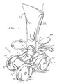
- the cleaner 10 includes a frame 12 on which a housing, consisting of an upper housing shell 14 and a lower housing shell 16, is mounted.
- An open suction mast 18 for vacuuming debris from beneath the cleaner 10 extends through an opening 20, generally in the middle of the upper housing shell 14, and a collection bag 22 is attached to the suction mast, over a flapper valve 24 positioned on the upper end of the suction mast, to collect the debris.
- a pair of opposing jets 26 and 28 are located inside the suction mast 18 (FIG.
- a vertically oriented supply mast 30 extends through the opening 20 in the upper housing shell 14, behind the suction mast 18, to which a supply hose 32 is connected for delivering pressurized water to the cleaner 10.
- a float 34 is positioned on a support arm 36 formed integrally with, and projecting rearwardly from, the supply mast 30, and a sweep hose 38 is connected to a sweep hose jet 40 that similarly projects rearwardly from the supply mast.
- a thrust jet (not shown) is provided at the rear of the cleaner 10.
- a first wheel 42 and a second wheel 44 of equal size are positioned on opposite sides of the cleaner 10, forwardly of the suction mast 18, for rotation on a common axis.
- a turbine 46 is mounted within the frame 12 for producing rotary motion in response to a pressured water flow supplied thereto via hose 48, which connects to an outlet 50(FIG. 5) near the base of the supply mast 30, within the cleaner housing.
- the turbine 46 is conventional in design, having a water inlet port 52, a water wheel 54, a water outlet port (not shown), and a power output shaft 56 which is rotated in response to water being supplied to the inlet port 52.
- the power output shaft 56 extends axially in both directions from the turbine 46 and is journaled for rotation by nylon bearings 58 in mounting blocks 60 which are secured by screws 62 in the sidewalls of the frame 12.
- the opposite ends 64 and 66 of the output shaft 56 have splines formed thereon in the nature of gears.
- Each splined end 64 and 66 of the output shaft drivingly engages an annular rack 68 and 70 formed on the inner surface of the first wheel 42 and the second wheel 44, respectively, as seen in FIGS. 2, 3 and 5.
- the sizes of the first wheel 42 and the second wheel 44, and their position relative to the frame 12, are such that both wheels extend in the forward direction beyond the forward end of the frame.
- a third wheel 72 and a fourth wheel 74 of equal size are likewise positioned on opposite sides of the cleaner 10, rearwardly of the suction mast, and rotate on a common axis.
- neither the third wheel 72 nor the fourth wheel 74 are driven by the turbine 46. Instead, both the third wheel 72 and the fourth wheel 74 are mounted for freewheeling rotation.
- Each of the first wheel 42, the second wheel 44, the third wheel 72 and the fourth wheel 74 is mounted on an axle 76, and each wheel is held in place on the axle by a hub screw 78 and washer 80 (shown in FIG. 1), respectively.
- each axle 76 is integrally molded with a mounting block 82 that is secured in a recess formed in the frame 12 by a mounting plate 84 and screws 86.
- An elastomeric tire 88 is mounted on each wheel.
- the frame 12 Although a detailed plan view of the frame 12 is not illustrated in the drawings, it is contemplated that many openings will be formed in the frame over its lateral and longitudinal extent in order to make it as lightweight as practicable, consistent with maintaining appropriate structural strength. These openings in the frame 12 also serve to prevent air from becoming trapped in the cleaner 10 when it is first submerged in the swimming pool, causing the cleaner to float undesirably. At the same time, however, it is also contemplated that a brass weight (also not shown) will be mounted at the forward end of the frame 12 to increase the traction of the first and second wheels 42 and 44. Of course, the float 34 also has the effect of increasing the traction of the first and second wheels 42 and 44 by virtue of the relatively high elevational positioning of the float 34 at the rear of the cleaner 10.
- the forward end portion of the upper housing shell 14 includes a sloping portion 90.
- This sloping portion 90 comprises a substantially flat or linear surface having an angle of about 40 degrees to the horizontal plane of the cleaner 10 and comprises about one-half of the area of the surface of the upper housing shell 14 extending forwardly of the suction mast 18.
- the force of the water in the swimming pool on this sloping portion 90 advantageously tends to push the front of the cleaner in a downward direction.
- This downward force in conjunction with the downward force of the aforementioned brass weight and the counterbalancing force applied by the float 34, further increase the traction of the first and second wheels 42 and 44 and reduces the tendency of the front of the cleaner 10 to lift off the submerged surfaces of the swimming pool as the cleaner is propelled in the forward direction.
- a spoiler 92 in the form of a relatively long and narrow vee-shaped plate is shown mounted on the upper housing shell 14 forwardly of the suction mast 18. As shown in FIG. 7, for convenience of fabrication the spoiler 92 can be formed as a separate part and mounted with a snap fit in openings 94 formed in the upper housing shell 14.
Landscapes
- Engineering & Computer Science (AREA)
- Architecture (AREA)
- Civil Engineering (AREA)
- Structural Engineering (AREA)
- Cleaning In General (AREA)
- Detergent Compositions (AREA)
- Organic Low-Molecular-Weight Compounds And Preparation Thereof (AREA)
- Electric Suction Cleaners (AREA)
- Gyroscopes (AREA)
- Telephone Function (AREA)
Claims (9)
- Dispositif de nettoyage automatique de piscine actionné à partir d'eau pompée et apte à se déplacer le long des surfaces immergées d'une piscine, comprenant :caractérisé en ce que :un cadre (12) ;un carter (14) monté sur ledit cadre ;une pluralité de roues (42, 44, 72, 74) montées sur ledit cadre et positionnées à l'extérieur dudit carter ;des moyens d'alimentation en eau (30) supportés par ledit cadre comprenant un orifice d'entrée pour recevoir une alimentation en eau par l'intermédiaire d'un tuyau d'alimentation (32) et un orifice de sortie (50) ;une turbine (46) ;des moyens d'entraínement (56, 68, 70) ; etun système d'aspiration (18, 24, 26, 28, 32) comprenant un sac de collecte (32) et des moyens (26, 28) pour générer une circulation d'eau à proximité des surfaces immergées d'une piscine dans ledit sac pour entraíner des débris de l'intérieur de la piscine dans ledit sac de collecte, ledit système d'aspiration comprenant un mât d'aspiration (18) monté sur ledit carter à une extrémité supérieure disposée généralement au-dessus dudit carter, ledit sac de collecte étant d'une manière générale monté à l'extrémité supérieure dudit mât d'aspiration ;ladite pluralité de roues comprend des première (42) et deuxième (44) roues montées à une extrémité avant dudit cadre sur des côtés opposés dudit carter en avant du mât d'aspiration s'étendant au-delà de l'extrémité avant dudit cadre et dudit carter ; et des troisième (72) et quatrième (74) roues montées sur les côtés opposés dudit carter ;la turbine est montée sur ledit cadre et positionnée à l'intérieur dudit carter, ladite turbine étant accouplée audit orifice de sortie (56) desdits moyens d'alimentation en eau et tournant en réponse à l'eau délivrée via lesdits moyens d'alimentation en eau ; etlesdits moyens d'entraínement accouplent ladite turbine (46) auxdites première et deuxième roues pour entraíner lesdites première et deuxième roues en réponse à l'eau délivrée à ladite turbine, lesdites première et deuxième roues propulsant ledit dispositif de nettoyage en avant le long des surfaces immergées de la piscine.
- Dispositif de nettoyage automatique de piscine selon la revendication 1, dans lequel une extrémité avant d'une surface supérieure dudit carter comprend une partie inclinée (90) afin de réduire la tendance du dispositif de nettoyage à se soulever des surfaces immergées de la piscine alors que les première et deuxième roues propulsent le dispositif de nettoyage en avant.
- Dispositif de nettoyage automatique de piscine selon la revendication 2, dans lequel ladite partie inclinée (90) de ladite extrémité avant de ladite surface supérieure dudit carter comprend au moins environ la moitié de l'aire de ladite surface supérieure s'étendant en avant dudit mât d'aspiration.
- Dispositif de nettoyage automatique de piscine selon la revendication 2, dans lequel ladite partie inclinée (90) de ladite extrémité avant de ladite surface supérieure dudit carter présente une inclinaison sensiblement linéaire selon un angle d'environ 40 degrés.
- Dispositif de nettoyage automatique de piscine selon l'une quelconque des revendications précédentes, comprenant un stabilisateur (92) positionné sur une surface supérieure dudit carter en avant dudit mât d'aspiration afin de réduire la tendance du dispositif de nettoyage se soulever des surfaces immergées de la piscine alors que les première et deuxième roues propulsent le dispositif de nettoyage en avant.
- Dispositif de nettoyage automatique de piscine selon l'une quelconque des revendications précédentes, dans lequel lesdits moyens d'entraínement comprennent un essieu moteur (66) accouplé à la turbine et en prise avec lesdites première et deuxième roues.
- Dispositif de nettoyage automatique de piscine selon l'une quelconque des revendications précédentes, dans lequel les troisième et quatrième roues sont montées pour tourner autour d'un premier axe commun.
- Dispositif de nettoyage automatique de piscine selon la revendication 7, dans lequel lesdites troisième et quatrième roues sont montées pour tourner autour d'un deuxième axe commun.
- Dispositif de nettoyage automatique de piscine selon la revendication 8, dans lequel lesdites troisième et quatrième roues sont montées pour tourner en roue libre.
Applications Claiming Priority (3)
| Application Number | Priority Date | Filing Date | Title |
|---|---|---|---|
| US741957 | 1996-10-31 | ||
| US08/741,957 US5893188A (en) | 1996-10-31 | 1996-10-31 | Automatic swimming pool cleaner |
| PCT/GB1997/002998 WO1998019029A1 (fr) | 1996-10-31 | 1997-10-31 | Nettoyeur de piscine |
Publications (2)
| Publication Number | Publication Date |
|---|---|
| EP0948689A1 EP0948689A1 (fr) | 1999-10-13 |
| EP0948689B1 true EP0948689B1 (fr) | 2003-09-03 |
Family
ID=24982933
Family Applications (1)
| Application Number | Title | Priority Date | Filing Date |
|---|---|---|---|
| EP97910551A Expired - Lifetime EP0948689B1 (fr) | 1996-10-31 | 1997-10-31 | Nettoyeur de piscine |
Country Status (8)
| Country | Link |
|---|---|
| US (2) | US5893188A (fr) |
| EP (1) | EP0948689B1 (fr) |
| AT (1) | ATE248972T1 (fr) |
| AU (1) | AU725207B2 (fr) |
| DE (1) | DE69724648D1 (fr) |
| ES (1) | ES2206690T3 (fr) |
| WO (1) | WO1998019029A1 (fr) |
| ZA (1) | ZA979845B (fr) |
Families Citing this family (38)
| Publication number | Priority date | Publication date | Assignee | Title |
|---|---|---|---|---|
| US5933899A (en) * | 1996-10-31 | 1999-08-10 | Letro Products, Inc. | Low pressure automatic swimming pool cleaner |
| US5893188A (en) * | 1996-10-31 | 1999-04-13 | Letro Products, Inc. | Automatic swimming pool cleaner |
| US6193885B1 (en) | 1998-12-14 | 2001-02-27 | Letro Products, Inc. | Pool cleaner debris bag |
| US6971136B2 (en) * | 1999-01-25 | 2005-12-06 | Aqua Products, Inc. | Cleaner with high pressure cleaning jets |
| US8434182B2 (en) | 1999-01-25 | 2013-05-07 | Aqua Products, Inc. | Pool cleaner with high pressure cleaning jets |
| US6539573B1 (en) * | 1999-04-05 | 2003-04-01 | Michael A. Caccavella | JetNet |
| US6379542B1 (en) * | 2000-09-15 | 2002-04-30 | Letro Products, Inc. | Pool cleaner with righting weight assembly |
| ATE452260T1 (de) * | 2001-07-03 | 2010-01-15 | Pentair Pool Products Inc | Untergestell für ein automatisches schwimmbeckenreinigungsgerät |
| EP1490568A4 (fr) | 2002-03-29 | 2009-05-13 | Polaris Pool Sys Inc | Robot nettoyeur pour piscine |
| USD471330S1 (en) | 2002-06-25 | 2003-03-04 | Letro Products, Inc. | Automatic swimming pool cleaner |
| US7029583B2 (en) * | 2003-08-20 | 2006-04-18 | Polaris Pool Systems Inc. | Hose clasp for a pool cleaner filter bag |
| US7373948B2 (en) | 2004-01-21 | 2008-05-20 | Pentair Water Pool And Spa, Inc. | Variable output pressure backup valve |
| FR2870282B1 (fr) * | 2004-05-12 | 2008-11-14 | Lagon Sa | Appareil motorise nettoyeur de piscine comportant des moyens rotatifs de deplacement a roue libre |
| US7455782B2 (en) * | 2006-03-24 | 2008-11-25 | Kenneth Benscoter | Grit removal system and method for emergency water reservoir |
| US7506770B2 (en) * | 2006-06-30 | 2009-03-24 | Poolvergnuegen | Pool cleaner storage device |
| US8343339B2 (en) | 2008-09-16 | 2013-01-01 | Hayward Industries, Inc. | Apparatus for facilitating maintenance of a pool cleaning device |
| US9593502B2 (en) | 2009-10-19 | 2017-03-14 | Hayward Industries, Inc. | Swimming pool cleaner |
| US8968559B2 (en) | 2010-05-14 | 2015-03-03 | Pentair Water Pool And Spa, Inc. | Biodegradable disposable debris bag |
| US8784652B2 (en) | 2010-09-24 | 2014-07-22 | Poolvergnuegen | Swimming pool cleaner with a rigid debris canister |
| US8869337B2 (en) | 2010-11-02 | 2014-10-28 | Hayward Industries, Inc. | Pool cleaning device with adjustable buoyant element |
| US8990990B2 (en) | 2011-10-03 | 2015-03-31 | Pentair Water Pool And Spa, Inc. | Pool cleaner with hydraulic timer assembly |
| US8956533B2 (en) | 2011-10-03 | 2015-02-17 | Pentair Water Pool And Spa, Inc. | Pool cleaner with multi-stage venturi vacuum assembly |
| US9119463B2 (en) | 2011-10-03 | 2015-09-01 | Pentair Water Pool & Spa, Inc. | Pool cleaner with detachable scrubber assembly |
| CA2905970C (fr) | 2013-03-13 | 2018-02-13 | Pentair Water Pool And Spa, Inc. | Mecanisme a deux aubes pour appareil de nettoyage de piscine |
| WO2014160312A1 (fr) | 2013-03-14 | 2014-10-02 | Hayward Industries, Inc. | Système de nettoyage pour piscine avec des éléments de nettoyage articulés |
| WO2014150506A1 (fr) | 2013-03-15 | 2014-09-25 | Hayward Industries, Inc. | Dispositif de nettoyage de piscine doté d'ensembles entraînement de roue |
| ES2923669T3 (es) | 2013-08-30 | 2022-09-29 | Hayward Ind Inc | Limpiador de piscina |
| USD789624S1 (en) | 2014-11-07 | 2017-06-13 | Hayward Industries, Inc. | Pool cleaner |
| USD787761S1 (en) | 2014-11-07 | 2017-05-23 | Hayward Industries, Inc. | Pool cleaner |
| USD789003S1 (en) | 2014-11-07 | 2017-06-06 | Hayward Industries, Inc. | Pool cleaner |
| USD787760S1 (en) | 2014-11-07 | 2017-05-23 | Hayward Industries, Inc. | Pool cleaner |
| CA2973916A1 (fr) | 2015-01-14 | 2016-07-21 | Pentair Water Pool And Spa, Inc. | Sac a debris comprenant un collier amovible |
| US10189490B2 (en) | 2017-05-11 | 2019-01-29 | Hayward Industries, Inc. | Pool cleaner caddy with removable wheel assemblies |
| US10227081B2 (en) | 2017-05-11 | 2019-03-12 | Hayward Industries, Inc. | Pool cleaner caddy with retention mechanism |
| EP4107346B1 (fr) | 2020-02-19 | 2025-05-14 | Pavel Sebor | Appareil de nettoyage automatique de piscine |
| USD1093786S1 (en) * | 2023-09-08 | 2025-09-16 | Sublue Underwater Ai Co., Ltd. | Swimming pool cleaning robot |
| USD1093785S1 (en) * | 2024-02-20 | 2025-09-16 | Hangzhou Kongyu Swimming Pool Co., Ltd. | Pool cleaner |
| USD1096030S1 (en) * | 2024-02-27 | 2025-09-30 | Sublue Underwater Ai Co., Ltd. | Automatic swimming pool cleaner |
Family Cites Families (15)
| Publication number | Priority date | Publication date | Assignee | Title |
|---|---|---|---|---|
| US3439368A (en) * | 1967-01-03 | 1969-04-22 | Robert R Myers | Swimming pool cleaner |
| AU464538B2 (en) * | 1969-04-23 | 1975-08-14 | Roy Myers Robert | Swimming pool cleaner |
| US3936899A (en) * | 1972-07-26 | 1976-02-10 | Henkin Melvyn Lane | Automatic swimming pool cleaner |
| US3822754A (en) * | 1972-07-26 | 1974-07-09 | M Henkin | Automatic swimming pool cleaner |
| US3972339A (en) * | 1974-03-07 | 1976-08-03 | Melvyn Lane Henkin | Automatic swimming pool cleaner |
| US4100641A (en) * | 1976-06-24 | 1978-07-18 | Pansini Andrew L | Swimming pool cleaners |
| US4558479A (en) * | 1984-01-26 | 1985-12-17 | Alopex Industries, Inc. | Pool cleaner |
| US5099535A (en) * | 1988-02-18 | 1992-03-31 | Daniel J. D. Chauvier | Cleaner for submerged surfaces |
| IT1217945B (it) * | 1988-06-28 | 1990-03-30 | Egatechnics Srl | Pulitore automatico semovente per piscine |
| ES2021813B3 (es) * | 1988-08-20 | 1991-11-16 | Pooltec Estab | Cabezal de aspiracion para limpiar superficies sumergidas |
| US5077853A (en) * | 1990-06-11 | 1992-01-07 | Campbell Sanford F | Pool cleaner |
| US5197158A (en) * | 1992-04-07 | 1993-03-30 | Philip L. Leslie | Swimming pool cleaner |
| US5542141A (en) * | 1995-04-10 | 1996-08-06 | Albright; Alva Z. | Water powered apparatus for cleaning aquatic bodies |
| US5603135A (en) * | 1995-10-31 | 1997-02-18 | Letro Products, Inc. | Pool cleaner with replaceable mast |
| US5893188A (en) * | 1996-10-31 | 1999-04-13 | Letro Products, Inc. | Automatic swimming pool cleaner |
-
1996
- 1996-10-31 US US08/741,957 patent/US5893188A/en not_active Expired - Lifetime
-
1997
- 1997-10-31 ZA ZA9709845A patent/ZA979845B/xx unknown
- 1997-10-31 AU AU47896/97A patent/AU725207B2/en not_active Expired
- 1997-10-31 AT AT97910551T patent/ATE248972T1/de not_active IP Right Cessation
- 1997-10-31 EP EP97910551A patent/EP0948689B1/fr not_active Expired - Lifetime
- 1997-10-31 ES ES97910551T patent/ES2206690T3/es not_active Expired - Lifetime
- 1997-10-31 WO PCT/GB1997/002998 patent/WO1998019029A1/fr not_active Ceased
- 1997-10-31 DE DE69724648T patent/DE69724648D1/de not_active Expired - Lifetime
-
1999
- 1999-02-04 US US09/244,852 patent/US6003184A/en not_active Expired - Lifetime
Also Published As
| Publication number | Publication date |
|---|---|
| ZA979845B (en) | 1998-05-25 |
| DE69724648D1 (de) | 2003-10-09 |
| EP0948689A1 (fr) | 1999-10-13 |
| AU4789697A (en) | 1998-05-22 |
| AU725207B2 (en) | 2000-10-05 |
| US6003184A (en) | 1999-12-21 |
| ES2206690T3 (es) | 2004-05-16 |
| US5893188A (en) | 1999-04-13 |
| WO1998019029A1 (fr) | 1998-05-07 |
| ATE248972T1 (de) | 2003-09-15 |
Similar Documents
| Publication | Publication Date | Title |
|---|---|---|
| US6003184A (en) | Automatic swimming pool cleaner | |
| US5933899A (en) | Low pressure automatic swimming pool cleaner | |
| US4768532A (en) | Underwater pool cleaner | |
| US3972339A (en) | Automatic swimming pool cleaner | |
| US4589986A (en) | Pool cleaner | |
| US3936899A (en) | Automatic swimming pool cleaner | |
| US4558479A (en) | Pool cleaner | |
| US3822754A (en) | Automatic swimming pool cleaner | |
| AU756881B2 (en) | Suction powered pool cleaner | |
| US10443259B2 (en) | Scrubber assembly for a pool cleaner | |
| US6665900B2 (en) | Pool cleaner | |
| US8627532B2 (en) | Pool cleaning vehicle having improved intake port | |
| US6942790B1 (en) | Open-air filtration cleaning device for pools and hot tubs | |
| US11118369B2 (en) | Pool cleaner with hydraulic timer assembly | |
| EP2769034B1 (fr) | Nettoyeur de bassin muni d'ensemble à vide à venturi à étages multiples | |
| EP0565226A1 (fr) | Appareil de nettoyage pour piscine | |
| AU2002301986B2 (en) | Suction Powered Pool Cleaner | |
| CA1061062A (fr) | Appareil pour le nettoyage automatique des piscines | |
| CA1116819A (fr) | Aspirateur automatique pour piscine | |
| CA1264509A (fr) | Dispositif nettoyeur de piscine |
Legal Events
| Date | Code | Title | Description |
|---|---|---|---|
| PUAI | Public reference made under article 153(3) epc to a published international application that has entered the european phase |
Free format text: ORIGINAL CODE: 0009012 |
|
| 17P | Request for examination filed |
Effective date: 19990517 |
|
| AK | Designated contracting states |
Kind code of ref document: A1 Designated state(s): AT BE CH DE DK ES FI FR GB GR IE IT LI LU MC NL PT SE |
|
| 17Q | First examination report despatched |
Effective date: 20000502 |
|
| GRAH | Despatch of communication of intention to grant a patent |
Free format text: ORIGINAL CODE: EPIDOS IGRA |
|
| GRAH | Despatch of communication of intention to grant a patent |
Free format text: ORIGINAL CODE: EPIDOS IGRA |
|
| GRAA | (expected) grant |
Free format text: ORIGINAL CODE: 0009210 |
|
| AK | Designated contracting states |
Kind code of ref document: B1 Designated state(s): AT BE CH DE DK ES FI FR GB GR IE IT LI LU MC NL PT SE |
|
| PG25 | Lapsed in a contracting state [announced via postgrant information from national office to epo] |
Ref country code: NL Free format text: LAPSE BECAUSE OF FAILURE TO SUBMIT A TRANSLATION OF THE DESCRIPTION OR TO PAY THE FEE WITHIN THE PRESCRIBED TIME-LIMIT Effective date: 20030903 Ref country code: LI Free format text: LAPSE BECAUSE OF FAILURE TO SUBMIT A TRANSLATION OF THE DESCRIPTION OR TO PAY THE FEE WITHIN THE PRESCRIBED TIME-LIMIT Effective date: 20030903 Ref country code: IT Free format text: LAPSE BECAUSE OF FAILURE TO SUBMIT A TRANSLATION OF THE DESCRIPTION OR TO PAY THE FEE WITHIN THE PRESCRIBED TIME-LIMIT;WARNING: LAPSES OF ITALIAN PATENTS WITH EFFECTIVE DATE BEFORE 2007 MAY HAVE OCCURRED AT ANY TIME BEFORE 2007. THE CORRECT EFFECTIVE DATE MAY BE DIFFERENT FROM THE ONE RECORDED. Effective date: 20030903 Ref country code: FI Free format text: LAPSE BECAUSE OF FAILURE TO SUBMIT A TRANSLATION OF THE DESCRIPTION OR TO PAY THE FEE WITHIN THE PRESCRIBED TIME-LIMIT Effective date: 20030903 Ref country code: CH Free format text: LAPSE BECAUSE OF FAILURE TO SUBMIT A TRANSLATION OF THE DESCRIPTION OR TO PAY THE FEE WITHIN THE PRESCRIBED TIME-LIMIT Effective date: 20030903 Ref country code: BE Free format text: LAPSE BECAUSE OF FAILURE TO SUBMIT A TRANSLATION OF THE DESCRIPTION OR TO PAY THE FEE WITHIN THE PRESCRIBED TIME-LIMIT Effective date: 20030903 Ref country code: AT Free format text: LAPSE BECAUSE OF FAILURE TO SUBMIT A TRANSLATION OF THE DESCRIPTION OR TO PAY THE FEE WITHIN THE PRESCRIBED TIME-LIMIT Effective date: 20030903 |
|
| REG | Reference to a national code |
Ref country code: GB Ref legal event code: FG4D |
|
| REG | Reference to a national code |
Ref country code: CH Ref legal event code: EP |
|
| REF | Corresponds to: |
Ref document number: 69724648 Country of ref document: DE Date of ref document: 20031009 Kind code of ref document: P |
|
| REG | Reference to a national code |
Ref country code: IE Ref legal event code: FG4D |
|
| PG25 | Lapsed in a contracting state [announced via postgrant information from national office to epo] |
Ref country code: MC Free format text: LAPSE BECAUSE OF NON-PAYMENT OF DUE FEES Effective date: 20031031 Ref country code: LU Free format text: LAPSE BECAUSE OF NON-PAYMENT OF DUE FEES Effective date: 20031031 Ref country code: IE Free format text: LAPSE BECAUSE OF NON-PAYMENT OF DUE FEES Effective date: 20031031 |
|
| PG25 | Lapsed in a contracting state [announced via postgrant information from national office to epo] |
Ref country code: SE Free format text: LAPSE BECAUSE OF FAILURE TO SUBMIT A TRANSLATION OF THE DESCRIPTION OR TO PAY THE FEE WITHIN THE PRESCRIBED TIME-LIMIT Effective date: 20031203 Ref country code: GR Free format text: LAPSE BECAUSE OF FAILURE TO SUBMIT A TRANSLATION OF THE DESCRIPTION OR TO PAY THE FEE WITHIN THE PRESCRIBED TIME-LIMIT Effective date: 20031203 Ref country code: GB Free format text: LAPSE BECAUSE OF NON-PAYMENT OF DUE FEES Effective date: 20031203 Ref country code: DK Free format text: LAPSE BECAUSE OF FAILURE TO SUBMIT A TRANSLATION OF THE DESCRIPTION OR TO PAY THE FEE WITHIN THE PRESCRIBED TIME-LIMIT Effective date: 20031203 |
|
| PG25 | Lapsed in a contracting state [announced via postgrant information from national office to epo] |
Ref country code: DE Free format text: LAPSE BECAUSE OF FAILURE TO SUBMIT A TRANSLATION OF THE DESCRIPTION OR TO PAY THE FEE WITHIN THE PRESCRIBED TIME-LIMIT Effective date: 20031204 |
|
| RAP2 | Party data changed (patent owner data changed or rights of a patent transferred) |
Owner name: PENTAIR POOL PRODUCTS, INC. |
|
| NLV1 | Nl: lapsed or annulled due to failure to fulfill the requirements of art. 29p and 29m of the patents act | ||
| PG25 | Lapsed in a contracting state [announced via postgrant information from national office to epo] |
Ref country code: PT Free format text: LAPSE BECAUSE OF FAILURE TO SUBMIT A TRANSLATION OF THE DESCRIPTION OR TO PAY THE FEE WITHIN THE PRESCRIBED TIME-LIMIT Effective date: 20040203 |
|
| REG | Reference to a national code |
Ref country code: CH Ref legal event code: PL |
|
| REG | Reference to a national code |
Ref country code: ES Ref legal event code: FG2A Ref document number: 2206690 Country of ref document: ES Kind code of ref document: T3 |
|
| ET | Fr: translation filed | ||
| PLBE | No opposition filed within time limit |
Free format text: ORIGINAL CODE: 0009261 |
|
| STAA | Information on the status of an ep patent application or granted ep patent |
Free format text: STATUS: NO OPPOSITION FILED WITHIN TIME LIMIT |
|
| GBPC | Gb: european patent ceased through non-payment of renewal fee |
Effective date: 20031203 |
|
| REG | Reference to a national code |
Ref country code: IE Ref legal event code: MM4A |
|
| 26N | No opposition filed |
Effective date: 20040604 |
|
| REG | Reference to a national code |
Ref country code: FR Ref legal event code: TP |
|
| REG | Reference to a national code |
Ref country code: FR Ref legal event code: PLFP Year of fee payment: 19 |
|
| REG | Reference to a national code |
Ref country code: FR Ref legal event code: PLFP Year of fee payment: 20 |
|
| PGFP | Annual fee paid to national office [announced via postgrant information from national office to epo] |
Ref country code: FR Payment date: 20161025 Year of fee payment: 20 |
|
| PGFP | Annual fee paid to national office [announced via postgrant information from national office to epo] |
Ref country code: ES Payment date: 20161026 Year of fee payment: 20 |
|
| REG | Reference to a national code |
Ref country code: ES Ref legal event code: FD2A Effective date: 20180508 |
|
| PG25 | Lapsed in a contracting state [announced via postgrant information from national office to epo] |
Ref country code: ES Free format text: LAPSE BECAUSE OF EXPIRATION OF PROTECTION Effective date: 20171101 |