EP0949182A2 - Dispositif de transport de récipients recevant du matériel - Google Patents
Dispositif de transport de récipients recevant du matériel Download PDFInfo
- Publication number
- EP0949182A2 EP0949182A2 EP99101437A EP99101437A EP0949182A2 EP 0949182 A2 EP0949182 A2 EP 0949182A2 EP 99101437 A EP99101437 A EP 99101437A EP 99101437 A EP99101437 A EP 99101437A EP 0949182 A2 EP0949182 A2 EP 0949182A2
- Authority
- EP
- European Patent Office
- Prior art keywords
- load
- projections
- transport device
- receptacles
- arms
- Prior art date
- Legal status (The legal status is an assumption and is not a legal conclusion. Google has not performed a legal analysis and makes no representation as to the accuracy of the status listed.)
- Granted
Links
Images


Classifications
-
- B—PERFORMING OPERATIONS; TRANSPORTING
- B66—HOISTING; LIFTING; HAULING
- B66C—CRANES; LOAD-ENGAGING ELEMENTS OR DEVICES FOR CRANES, CAPSTANS, WINCHES, OR TACKLES
- B66C1/00—Load-engaging elements or devices attached to lifting or lowering gear of cranes or adapted for connection therewith for transmitting lifting forces to articles or groups of articles
- B66C1/10—Load-engaging elements or devices attached to lifting or lowering gear of cranes or adapted for connection therewith for transmitting lifting forces to articles or groups of articles by mechanical means
- B66C1/62—Load-engaging elements or devices attached to lifting or lowering gear of cranes or adapted for connection therewith for transmitting lifting forces to articles or groups of articles by mechanical means comprising article-engaging members of a shape complementary to that of the articles to be handled
- B66C1/66—Load-engaging elements or devices attached to lifting or lowering gear of cranes or adapted for connection therewith for transmitting lifting forces to articles or groups of articles by mechanical means comprising article-engaging members of a shape complementary to that of the articles to be handled for engaging holes, recesses, or abutments on articles specially provided for facilitating handling thereof
Definitions
- the invention relates to a transport device for containers Recording of the material, the containers at least two in essential vertical, opposite side parts and on the outside at least one protrusion for the engagement each have two load receptacles and each side part at least a load arm is assigned to a lifting system, the load receptacles at the bottom of one is essentially vertical extending swivel arm are arranged and the swivel arm with its other end on the load arm rotatable about a horizontal axis is articulated to adjust the load capacity between one Position horizontally next to the protrusions and one position below the ledges.
- containers come in a wide variety kind of question, as for example through boxes or crates, pallets, Lattice boxes, cassettes or yokes are given. Is essential only that the containers at least two opposite each other Have side panels.
- Materials can be solid, in the form of Components, piece goods etc., however, are equally bulk goods.
- Cassettes or yokes are stored and transported in particular in connection with a warehouse for rod-shaped material to supply cutting machines in the form of band saws or Cold circular saws for cutting pieces of material from such rod-shaped material.
- a transport device is the beginning mentioned type known from EP 0 770 564 A2. It solves the task a simple and stable recording of yokes to theirs automated handling by the lifting system both in Regarding in one plane aligned yokes as well with regard to several yokes stacked on top of each other. This requires however, to actuate the load receptacles respectively electrical, hydraulic or pneumatic actuators, which in special case is portable, in general scope for very different containers, however, the facility is often too much expensive and complicated if you still have the necessary for the actuating means Control devices included in the consideration.
- the object of the invention is therefore to provide a transport device to design differently in that way in particular that also for general or simple applications of the load pick-ups on site without the need for a feed external energy and actuating means operated by this is possible.
- the design to be undertaken in this context should simple, robust and reliable as well as with regard to the production costs to be without special influence.
- This object is achieved in that a downward Movement of the load arms to lift the load from a in the vertical direction within the cross-sectional area of the projections located first position through the projections in an outside this cross-sectional area located second position are that on the swivel arms above the load supports Switching parts are arranged and that with an upward movement the load arms the switching parts through the projections in one Covering load receptacles and leading around the protrusions on the outside Position can be brought.
- each side part two in the horizontal direction has projections arranged side by side, so that for each A separate lead is available for load handling, with which in particular there is a high level of safety against tipping over for the containers especially when the containers are horizontal through the lifting system Movements are accelerated positively or negatively.
- the switching parts about a horizontal axis against a Restoring force can be rotated from a basic position on the swivel arms are stored and that the switching parts at a further downward Movement of the load arms through the projections from the Basic position can be turned aside and then upwards ongoing movement of the load arms through the projections from the Basic position in the opposite direction in which the load receptacles covering position are rotatable.
- the switching parts which are essentially in the form of a jack or one Switch cam can have, so by means of the restoring force in itself on the swivel arms in a neutral basic position held. Run with the corresponding downward movement of the Load arms from above on the protrusions, so they are against the Restoring force pivoted aside so that it is on the projections sliding these can happen to subsequently by the restoring force to be swiveled back into the basic position with which they are now below the projections.
- the switching parts their position covering the load bearing in the system Load pickups are so large that they are At least the top edges of the load receptacles in the direction of the projections cover if not towering over anything.
- the restoring force for the switching parts can by at least indirectly springs attacking them, supported on the swivel arms be formed and there can be systems from switching parts and springs in the basic position of the switching parts in the equilibrium state are located.
- the projections of the side parts can be open in the vertical direction Have hollow cross-section and it can be free, with the projections engaging ends of the load suspension with a be provided with a protruding nose. Grab with that nose then the load receptacles when lifting the containers into the hollow cross section of the protrusions so that the containers from the load receptacles are secured against slipping.
- this can essentially be one over the length of the containers between their side parts have extending, height-adjustable walking beams and it can the ends of the walking beam associated with the side parts from the walking beam in the vertical plane of the assigned side parts downwardly extending load arms.
- This design is for example useful for holding box-shaped containers, especially for picking up long pallets where the end faces are provided with the projections.
- height-adjustable walking beams have, on the sides of which the side parts of the containers assigned, itself from the walking beam in the vertical plane in the assigned Projections downwardly extending load arms are attached.
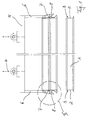
- FIG. 1 shows a stack of containers arranged one above the other in Form of elongated cassettes 1 for holding material, for example in the form of bars of metal.
- the cassettes 1 have with their end walls 2 opposite side parts, the are provided with horizontally projecting projections 3, over the they can be gripped and transported.
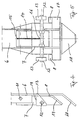
- FIG. 2 shows in Enlarged view partly of section II according to FIG. 1 and FIG. 3 shows the end view of the object according to FIG. 2.
- the side parts 2 over the height of the pallets 1st extended like a sword, on the other hand accordingly end with its lower edge 9 above the lower edge 10 of the cassette 1, so that stacked cassettes 1 with respect to each other Slipping are positively secured.
- the figures also show 2 and 3 that the projections 3 have a hollow cross section open in the vertical direction form, in which the hook-shaped load receptacles 8 also intervene positively.
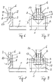
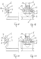
- FIGs 2 and 3 together with their enlarged partial representations in Figures 4 and 5 recognize that the load pickups 8 are located at the lower end of the swivel arms 7, the Swivel arms 7 pivotable on the load arms 6 via a shaft 11 are stored and hang down vertically from them in such a way that the load receptacles 8 in the vertical cross-sectional area are located above the projections 8.
- each switching part 13 On the swivel arms 7 are above the load receptacles 8 to the shaft 11 parallel shaft 12 a pair of pawl-shaped Switching parts 13 pivotally mounted, each switching part 13 one Load pickup 8 is assigned. Usually they are Switching parts 13 in the basic position shown in FIGS. 2 to 5, in which it is held by a restoring force in the form of a spring 14 be stored at 15 on the swivel arm 7 and attacks at 16 on the shaft 12, being for the said basic position the articulation point 16 is the surface area closest to the abutment 15 the shaft 17.
- This one A load bearing 8 is assigned to each protrusion, the one Side part 2 assigned load receptacles 8 on a common Swivel arm 7 are attached by the swivel arm 7 at the bottom End has a horizontally extending inclined surface 17, of the load receptacles 8 upwards towards the switching parts 13 protrude.
- the load arms 6 are also at their lower end with one of the side parts 2 provided inclined surface 18, which together with the sword-shaped extension of the side parts 2 that aligned threading of the load arms 6 along the side parts 2 facilitated.
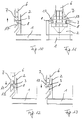
- the switching parts 13 extend from their one as possible large distance from the load arms 6 Shaft 12 essentially in the direction of the load arms 6 so far that them in their pivoting in the direction to be shown below on the load bearing 8 against the action of the restoring force of the Spring 14 come into contact with the load supports 8 from above and cover it upwards, then through the top edge 19 of the switching parts 13 one of the load receptacles 8 and Load arms 6 formed, upward inclined surface formed is, whose task also from the following description is clear, which now the operation of the so far described Device explained with reference to Figures 6 to 21.
- the load arms 6 are on it Drive down, with the load-bearing 8 sliding surfaces 17 from above onto the load supports 3 and on these have slid along so that they have the swivel arms 7 around their Articulation 11 on the load arms 6 from the side parts 2 of the pallets 1 have swung away.
- the load supports 8 Move around the outside of the projections 3 until they correspond Figures 8 and 9 go below the projections 3. Since the load receptacles 8 are released from the projections 3 here the swivel arms 7 can be returned to their original, Swing back vertically hanging position, at the load receptacles 8 are located below the projections 3.
- the load pickups are in one to the side parts 2 vertically directed manner and movable around the protrusions.
- the load receptacles are moved parallel to the side parts 2, but usually for this each load suspension of its own swivel arm together with a switching part mounted on it.
Landscapes
- Engineering & Computer Science (AREA)
- Mechanical Engineering (AREA)
- Load-Engaging Elements For Cranes (AREA)
- Warehouses Or Storage Devices (AREA)
- Supplying Of Containers To The Packaging Station (AREA)
- Control And Other Processes For Unpacking Of Materials (AREA)
- Stacking Of Articles And Auxiliary Devices (AREA)
- Replacing, Conveying, And Pick-Finding For Filamentary Materials (AREA)
- Attitude Control For Articles On Conveyors (AREA)
- Pallets (AREA)
- Packaging Of Machine Parts And Wound Products (AREA)
Applications Claiming Priority (2)
| Application Number | Priority Date | Filing Date | Title |
|---|---|---|---|
| DE29806424U | 1998-04-08 | ||
| DE29806424U DE29806424U1 (de) | 1998-04-08 | 1998-04-08 | Transportvorrichtung für Behältnisse zur Aufnahme von Material |
Publications (3)
| Publication Number | Publication Date |
|---|---|
| EP0949182A2 true EP0949182A2 (fr) | 1999-10-13 |
| EP0949182A3 EP0949182A3 (fr) | 2002-12-11 |
| EP0949182B1 EP0949182B1 (fr) | 2004-01-07 |
Family
ID=8055489
Family Applications (1)
| Application Number | Title | Priority Date | Filing Date |
|---|---|---|---|
| EP99101437A Expired - Lifetime EP0949182B1 (fr) | 1998-04-08 | 1999-01-27 | Dispositif de transport de récipients recevant du matériel |
Country Status (9)
| Country | Link |
|---|---|
| EP (1) | EP0949182B1 (fr) |
| JP (1) | JP4420485B2 (fr) |
| AT (1) | ATE257457T1 (fr) |
| AU (1) | AU748240B2 (fr) |
| CA (1) | CA2268334C (fr) |
| DE (2) | DE29806424U1 (fr) |
| DK (1) | DK0949182T3 (fr) |
| ES (1) | ES2212395T3 (fr) |
| IL (1) | IL128890A (fr) |
Families Citing this family (2)
| Publication number | Priority date | Publication date | Assignee | Title |
|---|---|---|---|---|
| DE102009026361A1 (de) * | 2009-08-11 | 2011-02-17 | Krones Ag | Greifervorrichtung zum gleichzeitigen Erfassen und/oder Greifen mehrerer Gebinde und/oder Kästen |
| NO343676B1 (en) * | 2017-09-20 | 2019-05-06 | Autostore Tech As | Container handling vehicle |
Family Cites Families (6)
| Publication number | Priority date | Publication date | Assignee | Title |
|---|---|---|---|---|
| DE3023689A1 (de) * | 1980-06-25 | 1982-01-14 | Rolf 4800 Bielefeld Hensel | Greifer fuer hebezeuge wie krane o.dgl. |
| GB9205257D0 (en) * | 1992-03-11 | 1992-04-22 | British Nuclear Fuels Plc | A lifting device |
| DE9305972U1 (de) * | 1993-04-20 | 1993-06-24 | Winden- und Maschinenbau Greßbach GmbH, 8753 Obernburg | Hebezeug mit Sicherheitsunterfangung |
| SE512158C2 (sv) * | 1994-05-27 | 2000-02-07 | Arne Froederberg | Med en lyftanordning förbundet lyftdon |
| DE29517134U1 (de) * | 1995-10-28 | 1995-12-21 | KEURO Besitz GmbH & Co EDV-Dienstleistungs KG, 77855 Achern | Vorrichtung zum Lagern und Transportieren von langen Werkstücken |
| GB2331506A (en) * | 1997-11-18 | 1999-05-26 | Powell Duffryn Standard Ltd | Container lifting |
-
1998
- 1998-04-08 DE DE29806424U patent/DE29806424U1/de not_active Expired - Lifetime
-
1999
- 1999-01-27 DK DK99101437T patent/DK0949182T3/da active
- 1999-01-27 EP EP99101437A patent/EP0949182B1/fr not_active Expired - Lifetime
- 1999-01-27 AT AT99101437T patent/ATE257457T1/de active
- 1999-01-27 ES ES99101437T patent/ES2212395T3/es not_active Expired - Lifetime
- 1999-01-27 DE DE59908220T patent/DE59908220D1/de not_active Expired - Lifetime
- 1999-03-09 IL IL12889099A patent/IL128890A/en not_active IP Right Cessation
- 1999-04-06 CA CA002268334A patent/CA2268334C/fr not_active Expired - Lifetime
- 1999-04-07 AU AU23636/99A patent/AU748240B2/en not_active Expired
- 1999-04-07 JP JP09948799A patent/JP4420485B2/ja not_active Expired - Lifetime
Also Published As
| Publication number | Publication date |
|---|---|
| DK0949182T3 (da) | 2004-03-29 |
| JP4420485B2 (ja) | 2010-02-24 |
| EP0949182B1 (fr) | 2004-01-07 |
| ATE257457T1 (de) | 2004-01-15 |
| ES2212395T3 (es) | 2004-07-16 |
| AU2363699A (en) | 1999-10-21 |
| CA2268334C (fr) | 2006-06-13 |
| EP0949182A3 (fr) | 2002-12-11 |
| JP2000086143A (ja) | 2000-03-28 |
| AU748240B2 (en) | 2002-05-30 |
| IL128890A (en) | 2001-07-24 |
| IL128890A0 (en) | 2000-01-31 |
| DE29806424U1 (de) | 1999-08-05 |
| DE59908220D1 (de) | 2004-02-12 |
| CA2268334A1 (fr) | 1999-10-08 |
Similar Documents
| Publication | Publication Date | Title |
|---|---|---|
| EP0377398A1 (fr) | Robot pour palettiser | |
| EP0482406A1 (fr) | Dispositif de maniement pour articles tels que cartons | |
| EP0377399A1 (fr) | Dispositif de préhension | |
| DE69407213T2 (de) | Plattentrennmaschine | |
| EP0770564B1 (fr) | Dispositif de stockage et de transport de pièces longues | |
| DE29803921U1 (de) | Stapelsäule zur Aufnahme einer Vielzahl von flächigen Werkstücken | |
| DE102022116081A1 (de) | System mit einem Greifer | |
| EP2700597B1 (fr) | Dispositif et procédé pour empiler ou désempiler des caisses | |
| EP0436506A1 (fr) | Dispositif pour aligner des piles | |
| DE3517061C1 (de) | Regalfoerderzeug in Form eines Kranes | |
| DE10020909B4 (de) | Vorrichtung zur Förderung einer Vorratsrolle | |
| EP4174015B1 (fr) | Unité de transport de porteurs de charge avec garde au sol améliorée | |
| DE2331936C3 (de) | Trag- und Hubvorrichtung zum Abheben eines Plattenstapels von den untersten Platten desselben | |
| DE3907332A1 (de) | Greifvorrichtung | |
| EP0949182B1 (fr) | Dispositif de transport de récipients recevant du matériel | |
| DE19815689C1 (de) | Transportvorrichtung für Behältnisse zur Aufnahme von Material | |
| DE19711464C2 (de) | Verfahren zum Stapeln von Transportkisten und Transportkistenstapellager | |
| AT405504B (de) | Drehvorrichtung für plattenförmige werkstücke oder werkstückpakete, insbesondere für eine sortier- und stapelanlage für formatzuschnitte an einer plattenaufteilanlage | |
| EP1557382B1 (fr) | Dispositif pour le prélèvement de palettes vides | |
| DE69018183T2 (de) | Vorrichtung und Verfahren zum Laden von Stückgütern. | |
| DE1966372C3 (de) | Einrichtung zum Überführen von Lastenträgern für Schleppkreisförderer von einer ersten Antriebsschiene auf eine zweite. Ausscheidung aus: 1944345 | |
| DE3531800A1 (de) | Vorrichtung zum lagern von teilen im abstand zueinander insbesondere zum lagern von blechen oder blechformteilen | |
| EP0576821A1 (fr) | Dispositif pour le prélèvement automatique d'objets empilés de façon couchée et de forme essentiellement cylindrique | |
| EP0004616B1 (fr) | Bac en matière plastique, en particulier bac à poisson et appareil de levage pour un tel bac | |
| DE9301707U1 (de) | Palettenmagazin |
Legal Events
| Date | Code | Title | Description |
|---|---|---|---|
| PUAI | Public reference made under article 153(3) epc to a published international application that has entered the european phase |
Free format text: ORIGINAL CODE: 0009012 |
|
| AK | Designated contracting states |
Kind code of ref document: A2 Designated state(s): AT BE CH CY DE DK ES FI FR GB GR IE IT LI LU MC NL PT SE |
|
| AX | Request for extension of the european patent |
Free format text: AL;LT;LV;MK;RO;SI |
|
| PUAL | Search report despatched |
Free format text: ORIGINAL CODE: 0009013 |
|
| AK | Designated contracting states |
Kind code of ref document: A3 Designated state(s): AT BE CH CY DE DK ES FI FR GB GR IE IT LI LU MC NL PT SE |
|
| AX | Request for extension of the european patent |
Free format text: AL;LT;LV;MK;RO;SI |
|
| 17P | Request for examination filed |
Effective date: 20030118 |
|
| 17Q | First examination report despatched |
Effective date: 20030310 |
|
| GRAP | Despatch of communication of intention to grant a patent |
Free format text: ORIGINAL CODE: EPIDOSNIGR1 |
|
| AKX | Designation fees paid |
Designated state(s): AT BE CH DE DK ES FI FR GB IT LI NL SE |
|
| GRAS | Grant fee paid |
Free format text: ORIGINAL CODE: EPIDOSNIGR3 |
|
| GRAA | (expected) grant |
Free format text: ORIGINAL CODE: 0009210 |
|
| AK | Designated contracting states |
Kind code of ref document: B1 Designated state(s): AT BE CH DE DK ES FI FR GB IT LI NL SE |
|
| REG | Reference to a national code |
Ref country code: GB Ref legal event code: FG4D Free format text: NOT ENGLISH |
|
| REG | Reference to a national code |
Ref country code: CH Ref legal event code: EP |
|
| REG | Reference to a national code |
Ref country code: SE Ref legal event code: TRGR |
|
| REG | Reference to a national code |
Ref country code: IE Ref legal event code: FG4D Free format text: GERMAN |
|
| REF | Corresponds to: |
Ref document number: 59908220 Country of ref document: DE Date of ref document: 20040212 Kind code of ref document: P |
|
| REG | Reference to a national code |
Ref country code: DK Ref legal event code: T3 |
|
| REG | Reference to a national code |
Ref country code: CH Ref legal event code: NV Representative=s name: R. A. EGLI & CO. PATENTANWAELTE |
|
| GBT | Gb: translation of ep patent filed (gb section 77(6)(a)/1977) | ||
| REG | Reference to a national code |
Ref country code: ES Ref legal event code: FG2A Ref document number: 2212395 Country of ref document: ES Kind code of ref document: T3 |
|
| REG | Reference to a national code |
Ref country code: IE Ref legal event code: FD4D |
|
| ET | Fr: translation filed | ||
| PLBE | No opposition filed within time limit |
Free format text: ORIGINAL CODE: 0009261 |
|
| STAA | Information on the status of an ep patent application or granted ep patent |
Free format text: STATUS: NO OPPOSITION FILED WITHIN TIME LIMIT |
|
| 26N | No opposition filed |
Effective date: 20041008 |
|
| PGFP | Annual fee paid to national office [announced via postgrant information from national office to epo] |
Ref country code: FI Payment date: 20130121 Year of fee payment: 15 Ref country code: SE Payment date: 20130122 Year of fee payment: 15 Ref country code: DK Payment date: 20130124 Year of fee payment: 15 |
|
| PGFP | Annual fee paid to national office [announced via postgrant information from national office to epo] |
Ref country code: BE Payment date: 20130121 Year of fee payment: 15 |
|
| BERE | Be: lapsed |
Owner name: *KEURO BESITZ G.M.B.H. & CO. EDV-DIENSTLEISTUNGS K Effective date: 20140131 |
|
| REG | Reference to a national code |
Ref country code: DK Ref legal event code: EBP Effective date: 20140131 |
|
| REG | Reference to a national code |
Ref country code: SE Ref legal event code: EUG |
|
| PG25 | Lapsed in a contracting state [announced via postgrant information from national office to epo] |
Ref country code: FI Free format text: LAPSE BECAUSE OF NON-PAYMENT OF DUE FEES Effective date: 20140127 |
|
| PG25 | Lapsed in a contracting state [announced via postgrant information from national office to epo] |
Ref country code: SE Free format text: LAPSE BECAUSE OF NON-PAYMENT OF DUE FEES Effective date: 20140128 |
|
| PG25 | Lapsed in a contracting state [announced via postgrant information from national office to epo] |
Ref country code: DK Free format text: LAPSE BECAUSE OF NON-PAYMENT OF DUE FEES Effective date: 20140131 Ref country code: BE Free format text: LAPSE BECAUSE OF NON-PAYMENT OF DUE FEES Effective date: 20140131 |
|
| PGFP | Annual fee paid to national office [announced via postgrant information from national office to epo] |
Ref country code: NL Payment date: 20150122 Year of fee payment: 17 |
|
| PGFP | Annual fee paid to national office [announced via postgrant information from national office to epo] |
Ref country code: GB Payment date: 20150123 Year of fee payment: 17 Ref country code: AT Payment date: 20150121 Year of fee payment: 17 |
|
| REG | Reference to a national code |
Ref country code: FR Ref legal event code: PLFP Year of fee payment: 18 |
|
| REG | Reference to a national code |
Ref country code: AT Ref legal event code: MM01 Ref document number: 257457 Country of ref document: AT Kind code of ref document: T Effective date: 20160127 |
|
| GBPC | Gb: european patent ceased through non-payment of renewal fee |
Effective date: 20160127 |
|
| REG | Reference to a national code |
Ref country code: NL Ref legal event code: MM Effective date: 20160201 |
|
| PG25 | Lapsed in a contracting state [announced via postgrant information from national office to epo] |
Ref country code: GB Free format text: LAPSE BECAUSE OF NON-PAYMENT OF DUE FEES Effective date: 20160127 |
|
| PG25 | Lapsed in a contracting state [announced via postgrant information from national office to epo] |
Ref country code: NL Free format text: LAPSE BECAUSE OF NON-PAYMENT OF DUE FEES Effective date: 20160201 Ref country code: AT Free format text: LAPSE BECAUSE OF NON-PAYMENT OF DUE FEES Effective date: 20160127 |
|
| REG | Reference to a national code |
Ref country code: FR Ref legal event code: PLFP Year of fee payment: 19 |
|
| REG | Reference to a national code |
Ref country code: FR Ref legal event code: PLFP Year of fee payment: 20 |
|
| PGFP | Annual fee paid to national office [announced via postgrant information from national office to epo] |
Ref country code: DE Payment date: 20180118 Year of fee payment: 20 Ref country code: CH Payment date: 20180125 Year of fee payment: 20 Ref country code: ES Payment date: 20180220 Year of fee payment: 20 |
|
| PGFP | Annual fee paid to national office [announced via postgrant information from national office to epo] |
Ref country code: IT Payment date: 20180126 Year of fee payment: 20 Ref country code: FR Payment date: 20180124 Year of fee payment: 20 |
|
| REG | Reference to a national code |
Ref country code: DE Ref legal event code: R071 Ref document number: 59908220 Country of ref document: DE |
|
| REG | Reference to a national code |
Ref country code: CH Ref legal event code: PL |
|
| REG | Reference to a national code |
Ref country code: ES Ref legal event code: FD2A Effective date: 20200803 |
|
| PG25 | Lapsed in a contracting state [announced via postgrant information from national office to epo] |
Ref country code: ES Free format text: LAPSE BECAUSE OF EXPIRATION OF PROTECTION Effective date: 20190128 |