EP0949345A2 - Outil en cermet - Google Patents
Outil en cermet Download PDFInfo
- Publication number
- EP0949345A2 EP0949345A2 EP99302465A EP99302465A EP0949345A2 EP 0949345 A2 EP0949345 A2 EP 0949345A2 EP 99302465 A EP99302465 A EP 99302465A EP 99302465 A EP99302465 A EP 99302465A EP 0949345 A2 EP0949345 A2 EP 0949345A2
- Authority
- EP
- European Patent Office
- Prior art keywords
- cermet
- coating layer
- component
- surface coating
- weight
- Prior art date
- Legal status (The legal status is an assumption and is not a legal conclusion. Google has not performed a legal analysis and makes no representation as to the accuracy of the status listed.)
- Withdrawn
Links
- 239000011195 cermet Substances 0.000 title claims abstract description 75
- 239000002345 surface coating layer Substances 0.000 claims abstract description 73
- 239000011230 binding agent Substances 0.000 claims description 45
- 229910052751 metal Inorganic materials 0.000 claims description 25
- 238000005520 cutting process Methods 0.000 claims description 16
- 229910052804 chromium Inorganic materials 0.000 claims description 5
- 229910052735 hafnium Inorganic materials 0.000 claims description 5
- 229910052750 molybdenum Inorganic materials 0.000 claims description 5
- 229910052759 nickel Inorganic materials 0.000 claims description 5
- 229910052758 niobium Inorganic materials 0.000 claims description 5
- 229910052715 tantalum Inorganic materials 0.000 claims description 5
- 229910052721 tungsten Inorganic materials 0.000 claims description 5
- 229910052720 vanadium Inorganic materials 0.000 claims description 5
- 229910052726 zirconium Inorganic materials 0.000 claims description 5
- 230000001747 exhibiting effect Effects 0.000 claims description 3
- 229910052719 titanium Inorganic materials 0.000 claims description 3
- 229910052782 aluminium Inorganic materials 0.000 claims description 2
- 238000003754 machining Methods 0.000 claims description 2
- 150000004767 nitrides Chemical class 0.000 claims description 2
- 239000007769 metal material Substances 0.000 claims 3
- 239000000919 ceramic Substances 0.000 claims 1
- 238000001816 cooling Methods 0.000 description 21
- 238000010304 firing Methods 0.000 description 19
- 239000000843 powder Substances 0.000 description 17
- 239000000203 mixture Substances 0.000 description 16
- IJGRMHOSHXDMSA-UHFFFAOYSA-N Atomic nitrogen Chemical compound N#N IJGRMHOSHXDMSA-UHFFFAOYSA-N 0.000 description 14
- 239000010936 titanium Substances 0.000 description 14
- 238000000034 method Methods 0.000 description 13
- 239000000463 material Substances 0.000 description 11
- 239000000523 sample Substances 0.000 description 11
- 239000002994 raw material Substances 0.000 description 9
- 229910052757 nitrogen Inorganic materials 0.000 description 8
- 238000012360 testing method Methods 0.000 description 7
- XKRFYHLGVUSROY-UHFFFAOYSA-N Argon Chemical compound [Ar] XKRFYHLGVUSROY-UHFFFAOYSA-N 0.000 description 6
- VEXZGXHMUGYJMC-UHFFFAOYSA-N Hydrochloric acid Chemical compound Cl VEXZGXHMUGYJMC-UHFFFAOYSA-N 0.000 description 6
- 230000003247 decreasing effect Effects 0.000 description 6
- 230000000694 effects Effects 0.000 description 6
- 239000012298 atmosphere Substances 0.000 description 5
- 230000015572 biosynthetic process Effects 0.000 description 5
- 230000006872 improvement Effects 0.000 description 5
- 239000011261 inert gas Substances 0.000 description 5
- 239000002245 particle Substances 0.000 description 5
- 230000008569 process Effects 0.000 description 5
- 230000006866 deterioration Effects 0.000 description 4
- 238000010894 electron beam technology Methods 0.000 description 4
- 239000007789 gas Substances 0.000 description 4
- 238000004519 manufacturing process Methods 0.000 description 4
- 238000002156 mixing Methods 0.000 description 4
- 238000012986 modification Methods 0.000 description 4
- 230000004048 modification Effects 0.000 description 4
- PXHVJJICTQNCMI-UHFFFAOYSA-N nickel Substances [Ni] PXHVJJICTQNCMI-UHFFFAOYSA-N 0.000 description 4
- GRYLNZFGIOXLOG-UHFFFAOYSA-N Nitric acid Chemical compound O[N+]([O-])=O GRYLNZFGIOXLOG-UHFFFAOYSA-N 0.000 description 3
- 229910052786 argon Inorganic materials 0.000 description 3
- 238000004140 cleaning Methods 0.000 description 3
- 238000010586 diagram Methods 0.000 description 3
- 238000007733 ion plating Methods 0.000 description 3
- 238000005259 measurement Methods 0.000 description 3
- 239000010955 niobium Substances 0.000 description 3
- 229910017604 nitric acid Inorganic materials 0.000 description 3
- 239000004033 plastic Substances 0.000 description 3
- 238000005245 sintering Methods 0.000 description 3
- CSCPPACGZOOCGX-UHFFFAOYSA-N Acetone Chemical compound CC(C)=O CSCPPACGZOOCGX-UHFFFAOYSA-N 0.000 description 2
- NRTOMJZYCJJWKI-UHFFFAOYSA-N Titanium nitride Chemical compound [Ti]#N NRTOMJZYCJJWKI-UHFFFAOYSA-N 0.000 description 2
- 239000000956 alloy Substances 0.000 description 2
- 229910045601 alloy Inorganic materials 0.000 description 2
- 238000004458 analytical method Methods 0.000 description 2
- 230000008901 benefit Effects 0.000 description 2
- 238000011156 evaluation Methods 0.000 description 2
- 239000011812 mixed powder Substances 0.000 description 2
- 239000002344 surface layer Substances 0.000 description 2
- MTPVUVINMAGMJL-UHFFFAOYSA-N trimethyl(1,1,2,2,2-pentafluoroethyl)silane Chemical compound C[Si](C)(C)C(F)(F)C(F)(F)F MTPVUVINMAGMJL-UHFFFAOYSA-N 0.000 description 2
- 229910000831 Steel Inorganic materials 0.000 description 1
- 229910010038 TiAl Inorganic materials 0.000 description 1
- 229910010037 TiAlN Inorganic materials 0.000 description 1
- ATJFFYVFTNAWJD-UHFFFAOYSA-N Tin Chemical compound [Sn] ATJFFYVFTNAWJD-UHFFFAOYSA-N 0.000 description 1
- RTAQQCXQSZGOHL-UHFFFAOYSA-N Titanium Chemical compound [Ti] RTAQQCXQSZGOHL-UHFFFAOYSA-N 0.000 description 1
- 238000000441 X-ray spectroscopy Methods 0.000 description 1
- 239000002253 acid Substances 0.000 description 1
- 238000010306 acid treatment Methods 0.000 description 1
- QZPSXPBJTPJTSZ-UHFFFAOYSA-N aqua regia Chemical compound Cl.O[N+]([O-])=O QZPSXPBJTPJTSZ-UHFFFAOYSA-N 0.000 description 1
- 238000003763 carbonization Methods 0.000 description 1
- 238000005229 chemical vapour deposition Methods 0.000 description 1
- 239000011247 coating layer Substances 0.000 description 1
- GUTLYIVDDKVIGB-UHFFFAOYSA-N cobalt atom Chemical compound [Co] GUTLYIVDDKVIGB-UHFFFAOYSA-N 0.000 description 1
- 239000003086 colorant Substances 0.000 description 1
- 230000000052 comparative effect Effects 0.000 description 1
- 239000010730 cutting oil Substances 0.000 description 1
- 230000007547 defect Effects 0.000 description 1
- 238000007872 degassing Methods 0.000 description 1
- 238000000280 densification Methods 0.000 description 1
- 238000009792 diffusion process Methods 0.000 description 1
- 239000006185 dispersion Substances 0.000 description 1
- 238000001035 drying Methods 0.000 description 1
- 238000004453 electron probe microanalysis Methods 0.000 description 1
- 238000004868 gas analysis Methods 0.000 description 1
- 238000010438 heat treatment Methods 0.000 description 1
- 238000004898 kneading Methods 0.000 description 1
- 239000010410 layer Substances 0.000 description 1
- 238000012423 maintenance Methods 0.000 description 1
- 230000007246 mechanism Effects 0.000 description 1
- 239000002184 metal Substances 0.000 description 1
- JAGQSESDQXCFCH-UHFFFAOYSA-N methane;molybdenum Chemical compound C.[Mo].[Mo] JAGQSESDQXCFCH-UHFFFAOYSA-N 0.000 description 1
- UNASZPQZIFZUSI-UHFFFAOYSA-N methylidyneniobium Chemical compound [Nb]#C UNASZPQZIFZUSI-UHFFFAOYSA-N 0.000 description 1
- NFFIWVVINABMKP-UHFFFAOYSA-N methylidynetantalum Chemical compound [Ta]#C NFFIWVVINABMKP-UHFFFAOYSA-N 0.000 description 1
- 239000004200 microcrystalline wax Substances 0.000 description 1
- 238000000465 moulding Methods 0.000 description 1
- 230000007935 neutral effect Effects 0.000 description 1
- 238000005121 nitriding Methods 0.000 description 1
- 239000012299 nitrogen atmosphere Substances 0.000 description 1
- 238000011056 performance test Methods 0.000 description 1
- 238000005240 physical vapour deposition Methods 0.000 description 1
- 238000005498 polishing Methods 0.000 description 1
- 239000012495 reaction gas Substances 0.000 description 1
- 238000005488 sandblasting Methods 0.000 description 1
- 238000001878 scanning electron micrograph Methods 0.000 description 1
- 239000002904 solvent Substances 0.000 description 1
- 238000004544 sputter deposition Methods 0.000 description 1
- 239000010959 steel Substances 0.000 description 1
- 229910003468 tantalcarbide Inorganic materials 0.000 description 1
- UONOETXJSWQNOL-UHFFFAOYSA-N tungsten carbide Chemical compound [W+]#[C-] UONOETXJSWQNOL-UHFFFAOYSA-N 0.000 description 1
Images


Classifications
-
- C—CHEMISTRY; METALLURGY
- C22—METALLURGY; FERROUS OR NON-FERROUS ALLOYS; TREATMENT OF ALLOYS OR NON-FERROUS METALS
- C22C—ALLOYS
- C22C29/00—Alloys based on carbides, oxides, nitrides, borides, or silicides, e.g. cermets, or other metal compounds, e.g. oxynitrides, sulfides
- C22C29/02—Alloys based on carbides, oxides, nitrides, borides, or silicides, e.g. cermets, or other metal compounds, e.g. oxynitrides, sulfides based on carbides or carbonitrides
- C22C29/04—Alloys based on carbides, oxides, nitrides, borides, or silicides, e.g. cermets, or other metal compounds, e.g. oxynitrides, sulfides based on carbides or carbonitrides based on carbonitrides
-
- B—PERFORMING OPERATIONS; TRANSPORTING
- B23—MACHINE TOOLS; METAL-WORKING NOT OTHERWISE PROVIDED FOR
- B23B—TURNING; BORING
- B23B27/00—Tools for turning or boring machines; Tools of a similar kind in general; Accessories therefor
- B23B27/14—Cutting tools of which the bits or tips or cutting inserts are of special material
- B23B27/141—Specially shaped plate-like cutting inserts, i.e. length greater or equal to width, width greater than or equal to thickness
-
- C—CHEMISTRY; METALLURGY
- C23—COATING METALLIC MATERIAL; COATING MATERIAL WITH METALLIC MATERIAL; CHEMICAL SURFACE TREATMENT; DIFFUSION TREATMENT OF METALLIC MATERIAL; COATING BY VACUUM EVAPORATION, BY SPUTTERING, BY ION IMPLANTATION OR BY CHEMICAL VAPOUR DEPOSITION, IN GENERAL; INHIBITING CORROSION OF METALLIC MATERIAL OR INCRUSTATION IN GENERAL
- C23C—COATING METALLIC MATERIAL; COATING MATERIAL WITH METALLIC MATERIAL; SURFACE TREATMENT OF METALLIC MATERIAL BY DIFFUSION INTO THE SURFACE, BY CHEMICAL CONVERSION OR SUBSTITUTION; COATING BY VACUUM EVAPORATION, BY SPUTTERING, BY ION IMPLANTATION OR BY CHEMICAL VAPOUR DEPOSITION, IN GENERAL
- C23C30/00—Coating with metallic material characterised only by the composition of the metallic material, i.e. not characterised by the coating process
- C23C30/005—Coating with metallic material characterised only by the composition of the metallic material, i.e. not characterised by the coating process on hard metal substrates
-
- B—PERFORMING OPERATIONS; TRANSPORTING
- B22—CASTING; POWDER METALLURGY
- B22F—WORKING METALLIC POWDER; MANUFACTURE OF ARTICLES FROM METALLIC POWDER; MAKING METALLIC POWDER; APPARATUS OR DEVICES SPECIALLY ADAPTED FOR METALLIC POWDER
- B22F5/00—Manufacture of workpieces or articles from metallic powder characterised by the special shape of the product
- B22F2005/001—Cutting tools, earth boring or grinding tool other than table ware
-
- B—PERFORMING OPERATIONS; TRANSPORTING
- B22—CASTING; POWDER METALLURGY
- B22F—WORKING METALLIC POWDER; MANUFACTURE OF ARTICLES FROM METALLIC POWDER; MAKING METALLIC POWDER; APPARATUS OR DEVICES SPECIALLY ADAPTED FOR METALLIC POWDER
- B22F2999/00—Aspects linked to processes or compositions used in powder metallurgy
-
- B—PERFORMING OPERATIONS; TRANSPORTING
- B23—MACHINE TOOLS; METAL-WORKING NOT OTHERWISE PROVIDED FOR
- B23B—TURNING; BORING
- B23B2200/00—Details of cutting inserts
- B23B2200/08—Rake or top surfaces
- B23B2200/085—Rake or top surfaces discontinuous
-
- B—PERFORMING OPERATIONS; TRANSPORTING
- B23—MACHINE TOOLS; METAL-WORKING NOT OTHERWISE PROVIDED FOR
- B23B—TURNING; BORING
- B23B2200/00—Details of cutting inserts
- B23B2200/20—Top or side views of the cutting edge
- B23B2200/201—Details of the nose radius and immediately surrounding area
-
- B—PERFORMING OPERATIONS; TRANSPORTING
- B23—MACHINE TOOLS; METAL-WORKING NOT OTHERWISE PROVIDED FOR
- B23B—TURNING; BORING
- B23B2200/00—Details of cutting inserts
- B23B2200/24—Cross section of the cutting edge
- B23B2200/245—Cross section of the cutting edge rounded
-
- Y—GENERAL TAGGING OF NEW TECHNOLOGICAL DEVELOPMENTS; GENERAL TAGGING OF CROSS-SECTIONAL TECHNOLOGIES SPANNING OVER SEVERAL SECTIONS OF THE IPC; TECHNICAL SUBJECTS COVERED BY FORMER USPC CROSS-REFERENCE ART COLLECTIONS [XRACs] AND DIGESTS
- Y10—TECHNICAL SUBJECTS COVERED BY FORMER USPC
- Y10T—TECHNICAL SUBJECTS COVERED BY FORMER US CLASSIFICATION
- Y10T428/00—Stock material or miscellaneous articles
- Y10T428/26—Web or sheet containing structurally defined element or component, the element or component having a specified physical dimension
- Y10T428/263—Coating layer not in excess of 5 mils thick or equivalent
- Y10T428/264—Up to 3 mils
- Y10T428/265—1 mil or less
Definitions
- the present invention relates to a cermet tool.
- a cermet sintered body which comprises a hard phase mainly comprising a carbonitride of Ti and a 4a, 5a, 6a Group element component other than Ti (V, Cr, Zr, Nb, Mo, Hf, Ta and W), the hard phase being bound with a binder metallic phase mainly comprising Ni and/or Co, is excellent in plastic deformation resistance, etc. in comparison to a super hard alloy which has conventionally been used, and thus it is becoming a main stream cutting tool.
- the cermet sintered body described above generally exhibits an appearance having a hue near black. Therefore, when wear proceeds with use as a tool, there is a case in which a worn part and a non-worn part therearound are difficult to distinguish by the naked eye. Therefore, problems may occur in that machining may proceed even when the life of the tool has expired which may damage a material to be cut, or on the other hand, a tool that can still be used is replaced due to a misjudgement that the life of the tool has expired.
- An object of the present invention is to provide a cermet tool in which distinction between a worn part and a non-worn part can be easily conducted by the naked eye, so that the time at which the life of the tool is expired, and the like can be suitably judged.
- the present invention provides the cermet tools described below.
- a cermet tool comprising a cermet
- JISZ8721 corresponds to the Munsell Color system. Therefore, the method for displaying colors are the same in both the JISZ8721 Color system and the Munsell color system.
- JIS stands for Japanese Industrial Standard.
- the present invention further provides a cermet tool wherein the surface coating layer has an appearance exhibiting a substantially achromatic color or a chromatic color belonging a hue range of from 5PB to 5Y via 5RP on a hue circle defined in JIS Z8721.
- a surface coating layer is formed on a surface outermost part of the cermet constituting an important part of the tool, the surface coating layer having an appearance lightness Vs and a saturation Cs in lightness defined in JIS Z8721 of the surface coating layer satisfying at least one of Vs of 6 or more and Cs of 4 or more.
- the appearance lightness Vs of the surface coating layer becomes less than 6 or its saturation Cs becomes less than 4, it is difficult to distinguish a worn part (for example, a spent corner part) and a non-worn part of the cermet tool by the naked eyes.
- a worn part for example, a spent corner part
- Cs non-worn part of the cermet tool
- the surface coating layer may have an appearance exhibiting a substantially achromatic color or a chromatic color belonging a hue range of from 5PB to 5Y via 5RP on a hue circle defined in JIS Z8721.
- the content of the Ti component with respect to the total hard phase metallic component is preferably from 50 to 80% by weight.
- the content of the Ti component is less than 50% by weight, it leads to deterioration of the plastic deformation resistance or the wear resistance of the cermet.
- the content of the Ti component exceeds 80% by weight, there may be a case in which the toughness of the cermet is deteriorated.
- the content of the Ti component is more preferably from 60 to 70% by weight.
- the content of the additional metallic element component M (hereinafter referred to as an M component) is suitably from 20 to 50% by weight.
- an M component is suitably from 20 to 50% by weight.
- the Ti component becomes relatively short, which leads to deterioration of plastic deformation resistance or wear resistance of the cermet.
- the content of the M component becomes less than 20% by weight, the Ti component becomes relatively excess, and there may be a case in that the toughness of the cermet is deteriorated.
- the content of the M component is more preferably from 30 to 40% by weight.
- the content of the C component in the cermet is suitably from 7 to 12% by weight, and preferably from 8 to 10% by weight. Due to the same reason, the content of the N component in the cermet is suitably from 3 to 8% by weight, and preferably from 5 to 6% by weight. Furthermore, as assuming that the content of the C component in the cermet is represented by x, and the content of the N component is represented by y, the value of y/(x+y) is suitably adjusted within the range more than 0.3 but less than 0.5.
- the surface coating layer can be formed by a gas phase film formation method, such as a physical vapor deposition method (an ion plating method, a sputtering method, etc.) and a chemical vapor deposition method.
- a gas phase film formation method such as a physical vapor deposition method (an ion plating method, a sputtering method, etc.) and a chemical vapor deposition method.
- a surface coating layer is formed on a surface outermost part of the cermet constituting an important part of the tool, the surface coating layer mainly comprising the same hard phase as in the main body part inside, in which a weight content of the binder metallic phase forming component is smaller than an average weight content of the binder metallic phase forming component throughout the cermet (or the weight content in the main body part); and a weight content WB1 of the binder metallic phase forming component in the surface coating layer of the cermet (reflecting the amount of the binder metallic phase in the surface coating layer) and a weight content WB2 of the binder metallic phase forming component of the main body part (reflecting the amount of the binder metallic phase in the main body part) is adjusted to be 0.1 ⁇ WB1/WB2 ⁇ 0.7.
- the surface coating layer has a smaller content of the binder metallic phase than the main body part, its hardness becomes higher than the main body part.
- a suitable amount of the binder metallic phase is present as converted to WB1/WB2 of 0.1 or more, breaking off or crumbling away of the hard phase is difficult to occur, and excellent characteristics is exhibited for toughness. As a result, the wear resistance of the tool can be greatly improved.
- the surface coating layer described above has an advantage in that it can be easily formed by modifying the surface of the cermet itself by the method described later, as different from a so-called post-formation type that is formed by using a raw material not originated from the constitutional component of the cermet by another step, such as the conventional hard coating layer by the gas phase film forming method.
- WB1/WB2 When WB1/WB2 becomes less than 0.1, the binder metallic phase in the surface coating layer becomes low which makes breaking off or dropping of the hard phase liable to occur, and the effect of improvement in wear resistance of the tool becomes insufficient. On the other hand, when WB1/WB2 exceeds 0.7, the hardness of the surface coating layer becomes lower, and the effect of improvement in wear resistance of the tool similarly becomes insufficient.
- WB1/WB2 is more preferably adjusted in a range of from 0.2 to 0.5.
- a weight content WR1 of the hard phase metallic element component (reflecting the amount of the hard phase in the surface coating layer) and a weight content WB of the binder metallic phase forming component in the surface coating layer of the cermet, and a weight content WR2 of the hard phase metallic element component (reflecting the amount of the hard phase in the main body part) and a weight content WB2 of the binder metallic phase forming component of a residual part (hereinafter referred to as a main body part) other than the surface coating layer are adjusted to be 0.005 ⁇ WB1/WR1 ⁇ 0.14 in the side of the surface coating layer and 0.05 ⁇ WB2/WR2 ⁇ 0.2 in the side of the main body part.
- the surface coating layer since the surface coating layer has a smaller content of the binder metallic phase than the main body part, it has a higher hardness than the main body part.
- a suitable amount of the binder metallic phase is present as converted to WB1/WR1 of 0.005 or more, dropping of the hard phase is difficult to occur, and excellent characteristics is exhibited for toughness. As a result, the wear resistance of the tool can be greatly improved. Furthermore, the advantage in production as similar to the constitution (A) described above can also be obtained.
- WB1/WR1 When WB1/WR1 becomes less than 0.005 in the side of the surface coating layer, the binder metallic phase in the surface coating layer becomes low which makes breaking away or dropping of the hard phase liable to occur, and the effect of improvement in wear resistance of the tool becomes insufficient. On the other hand, when WB1/WR1 exceeds 0.14, the amount of the binder metallic phase in the surface coating layer becomes excessive which makes the hardness insufficient, and the effect of improvement in wear resistance of the tool similarly becomes insufficient.
- WB1/WR1 is preferably adjusted in a range of from 0.01 to 0.11.
- WB2/WR2 When WB2/WR2 becomes less than 0.05 in the side of the main body part, the binder metallic phase becomes low which makes the material weak, which leads deterioration of chipping resistance of the cermet. On the other hand, when WB2/WR1 exceeds 0.2, the formed amount of the hard phase becomes low, and the wear resistance of the cermet becomes insufficient. WB2/WR2 is preferably adjusted in a range of from 0.07 to 0.16.
- the cermet tool having the constitution (A) or (B) described above can be easily produced by the process for production described below. That is, in the gist of the process for production, mixed powder obtained by mixing hard phase raw material powder and binder metallic phase raw material powder in prescribed amounts is molded into a prescribed shape, and the resulting molded article is fired at a firing temperature set in a range of from 1,450 to 1,650°C. After firing, cooling is conducted, in which an average cooling rate at least in a temperature range of from 1,450 to 1,300°C is from 7 to 50°C per minute, and an atmosphere containing nitrogen and/or an inert gas (such as argon) in a partial pressure of 50 torr or more is used as a cooling atmosphere at least in that temperature range.
- an inert gas such as argon
- the hard phase is formed based on the hard phase raw material powder
- the binder metallic phase is formed based on the binder metallic phase raw material powder, so as to form a cermet sintered body.
- the following is expected. That is, during firing, diffusion of the constitutional elements of the metallic phase occurs from the central part of the article to be fired toward the outer periphery.
- nitriding or carbonization of the hard phase particles is accelerated to cause particle growth of the hard phase in the surface part, and wettability between the hard phase and the binder metallic phase is decreased, so that a part of the binder metallic phase becomes liable to be flicked out (or liable to be evaporated). As a result, it is considered that the binder metallic phase of the surface part is decreased.
- a tool of the present invention in which a surface coating layer is formed on the surface of the cermet, can be easily produced by the surface modification of the cermet itself. Furthermore, because the surface modification is carried out on cooling after firing, a pretreatment such as surface polishing preceding the film formation is not necessary. As a result, the number of production steps of the tool can be effectively reduced, and the price of the tool can be lowered.
- the firing temperature exceeds 1,650°C, the growth of crystalline particles exceedingly proceeds to make difficult to ensure the necessary strength.
- the firing temperature is less than 1,450°C, densification of the material becomes insufficient, which leads a result of insufficient strength.
- the firing temperature is preferably in the range of from 1,500 to 1,650°C.
- the cooling rate in the temperature range of from 1,450 to 1,300°C becomes less than 7°C per minute, it leads deterioration of wear resistance of the tool. It is considered that this is because the content of the metallic phase in the surface coating layer becomes excessive. When it exceeds 50°C per minute, defects such as cracks are liable to be formed in the sintered body due to a thermal impact on cooling. Therefore, the cooling rate is suitably from 7 to 50°C per minute, and preferably from 10 to 30°C per minute.
- the temperature range, at which the cooling rate is maintained can be expanded to the higher temperature side than 1,450°C (for example, to the firing temperature) or to the lower temperature side than 1,300°C.
- the partial pressure of nitrogen and/or an inert gas in the cooling atmosphere becomes less than 50 torr, the formation of the surface coating layer is insufficient, which leads to insufficient wear resistance of the tool.
- the partial pressure of nitrogen and/or an inert gas is more preferably 100 torr or more. Nitrogen and an inert gas each can be used singly or can be used as a mixture.
- the weight content WR2 of the hard phase metallic element component and the weight content WB2 of the binder metallic phase forming component of the main body part of the cermet can be adjusted by the mixing ratio of the hard phase raw material powder and the binder metallic phase raw material powder.
- the weight content WR1 of the hard phase metallic element component and the weight content WB 1 of the binder metallic phase forming component can be adjusted by the mixing ratio described above, and also by the pressure of the atmospheric gas and/or the cooling rate upon cooling after firing. For example, in the case where WB1 (i.e., the amount of the binder metallic phase) is intended to be decreased, rapid cooling is conducted in an atmosphere of a relatively high pressure. In the case where it is intended to be increased, the inverse procedure to the above can be employed.
- the surface coating layer is formed through modification of the surface layer part of the cermet, in which the binder metallic phase is decreased.
- the content ratios among the individual metallic element components constituting the hard phase metallic element components are substantially the same as each other between the surface coating layer and the main body part. That is, the surface coating layer contains the hard phase having the same composition as in the main body part in an amount larger than the main body part, and thus a good wear resistance can be ensured.
- the thickness of the surface coating layer described above is suitably in the range of from 0.5 to 5 ⁇ m.
- the thickness of the surface coating layer becomes less than 0.5 ⁇ m, there may be a case in that the effect of improvement in wear resistance by the formation of the surface coating layer is insufficient.
- the thickness is larger than 5 ⁇ m, it leads to a problem in that pitching occurs in the surface coating layer because the surface coating layer is brittle in comparison to the main body part. Therefore, the thickness of the surface coating layer is suitably adjusted within the above-described range, preferably from 2 to 4 ⁇ m, and more preferably from 2.5 to 3 ⁇ m.
- the hue of the appearance of the surface coating layer can be within the range described above by suitably adjusting the formation conditions thereof. Furthermore, by subjecting the surface of the cermet after firing to an acid treatment, the surface coating layer can be modified.
- the appearance hue of the surface coating layer for example, can be adjusted (for example, increasing the saturation) by the modification, and there is a case in that the spent corner part can further easily distinguished.
- the above species of raw material powder were blended to have the component ratios A and B shown in Table 1, and mixed in a ball mill for 72 hours with acetone as a solvent. After the mixed powder was dried, it is subjected to kneading with the addition of a microwax series binder and drying, to make granuled powder by passing through a 60-mesh sieve. The granuled powder was then molded into a prescribed shape of a tool by press molding with a pressure of 1.5 ton/cm 2 , followed by being degreased (Table 3: Samples Nos. 1 to 6, provided that Nos. 5 and 6 were outside the scope of the present invention).
- the molded articles were installed in a firing furnace, and heated from room temperature to 1,200°C at an average temperature gradient of 10°C per minute, followed by maintaining at 1,200°C for 30 minutes for degassing, as shown in Figure 1, with maintaining the interior of the firing furnace to a nitrogen atmosphere of various partial pressure of 100 torr or less. Thereafter, a prescribed partial pressure of nitrogen or argon was introduced into the furnace to make the sintering atmospheres shown in Table 2, and the temperature was increased at a temperature increasing rate of 5°C per minute, followed by maintaining at a firing temperature (maximum temperature of 1,600°C) for 1 hour.
- the center part thereof was cut, and the cut surface was mirror polished. Then, the thickness and the composition of the surface coating layer and the composition of the main body part was measure with an EPMA (electron probe microanalyzer by an energy dispersion type X-ray spectroscopy method) of an SEM (scanning electron microscope) by the following manner. With respect to the thickness of the surface coating layer, the cut surface of the sintered body was observed with an SEM as a secondary electron beam image (magnification: 5,000), and it was measured from the resulting structural photograph.
- EPMA electron probe microanalyzer by an energy dispersion type X-ray spectroscopy method
- the boundary therebetween could be defined by the contrast thereof.
- the composition of the main body part was defined in the following manner.
- the center of the cut surface was enlarged by an SEM at a magnification of 5,000, and simultaneously an analysis region having a height of 30 ⁇ m and a width of 40 ⁇ m was set within the range of view.
- the characteristic X-ray intensity was measured with scanning an electron beam within that region, to determine the composition from the intensity ratio.
- Three of the analysis regions were set in different ranges of view, respectively, and an average of the composition values obtained from the three regions was finally designated as the objective composition value.
- the composition of the surface coating layer was similarly determined in such a manner that the cut surface was enlarged by an SEM at a magnification of 5,000, an electron beam probe having a diameter of 1 ⁇ m was irradiated in the range of view to measure the characteristic X-ray intensity for the respective components, and the composition was determined from the intensity ratio (in this case, the composition was calculated as an average value of the three locations).
- the results of measurement are shown in Table 3.
- Figure 2 is a scanning electron micrograph of the sintered body of Sample No. 1 (magnification: 5,000). The part of a depth of about 5 ⁇ m from the surface is a part that is specified as the surface coating layer by the measurement described above.
- the surface of the cermet sintered body produced with the same composition and firing conditions as in Sample No. 4 in Table 2 was subjected to a cleaning treatment by sand blasting.
- the treatment was conducted to an extent in that the surface coating layer formed on cooling after firing was not completely removed but a part thereof remained.
- the sample after subjecting to the cleaning treatment was also measure for the values WB1, WR1, WB2, WR2, WB1/WB2, WB1/WR1 and WB2/WR2 in the same manner described above. The values are shown in Table 4.
- Samples were produced by the manner in that, to the sample after subjecting to the cleaning treatment, films of TiN, TiCN and TiAlN respectively were formed on the surface thereof by the ion plating method to have a film thickness of 3 ⁇ m (Samples Nos. 7, 8 and 9).
- the ion plating is conducted, by using a target of a Ti metal or a TiAl alloy as a target, and an N 2 or C 2 H 2 gas as a reaction gas, with generation of arc between the target and the material to be treated at 800 V and 100 A.
- a sample, in which the surface coating layer formed on cooling after firing was completely removed was also produced (Sample No. 10).
- the appearance color thereof was determined by comparing with color samples, the hue, lightness and saturation of which had been known, by the naked eyes, so as to determine the appearance hue by the hue, lightness and saturation defined in JIS described above.
- the results are shown in Table 5.
- N as a saturation value means neutral or achromatic or without colour, such as grey.
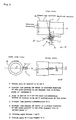
- the shape of the sintered body (hereinafter referred to as a tool) was that shown in Figure 3 (which is defined in ISO Standard as CCMT060204EN).
- the tool No. 1 had a thickness S of about 2.38 mm, a diameter of an inscribed circle C I of about 6.35 mm, and a flat shape of an approximate parallelogram cross section, and the size r ⁇ of radius provided at the respective corners was about 0.4 mm.
- the evaluation conditions for the cutting performance of the tools are as follows.
- a material to be cut W in the form of a rod was rotated around an axis as shown in Figure 4(a)
- the tool 1 shown in Figure 3 was made in contact with the outer circumferential surface thereof as shown in Figure 4(b)
- one of the primary plane 1c was used as a rake face (hereinafter the rake face is denoted by 1c')
- the side plane 1e Figure 3 was used as a flank face, so that the outer circumferential surface of the material to be cut W was continuously cut under the following conditions.
- Material to be cut Mn steel for machine structure (SNCM439) having a round rod shape (outer diameter: 240 mm, length: 200 mm, hardness: HB300) Cutting speed V 300 m/min Feed f 0.1 mm per rotation Depth of cut d 1.5 mm Cutting oil none Cutting time 4 minutes
- the cermet tools other than Samples Nos. 5 and 6 exhibit good wear resistance properties. It is understood that the judgement of the worn part by the naked eyes can be conducted when at least one of the appearance lightness Vs and the saturation Cs of the surface coating layer satisfy Vs of 6 or more and Cs of 4 or more. On the other hand, when the hue of the interior of the cermet (main body part) having been mirror polished was determined by using the color sample, the sample employing the composition A in Table 1 exhibited a lightness of 5 and a saturation of N, and that employing the composition B exhibited a lightness of 4 and a saturation of N.
Landscapes
- Chemical & Material Sciences (AREA)
- Engineering & Computer Science (AREA)
- Mechanical Engineering (AREA)
- Materials Engineering (AREA)
- Metallurgy (AREA)
- Organic Chemistry (AREA)
- Chemical Kinetics & Catalysis (AREA)
- Cutting Tools, Boring Holders, And Turrets (AREA)
- Coating Apparatus (AREA)
Applications Claiming Priority (2)
| Application Number | Priority Date | Filing Date | Title |
|---|---|---|---|
| JP10566998 | 1998-03-31 | ||
| JP10566998A JP3418336B2 (ja) | 1998-03-31 | 1998-03-31 | サーメット工具 |
Publications (2)
| Publication Number | Publication Date |
|---|---|
| EP0949345A2 true EP0949345A2 (fr) | 1999-10-13 |
| EP0949345A3 EP0949345A3 (fr) | 2002-08-14 |
Family
ID=14413860
Family Applications (1)
| Application Number | Title | Priority Date | Filing Date |
|---|---|---|---|
| EP99302465A Withdrawn EP0949345A3 (fr) | 1998-03-31 | 1999-03-30 | Outil en cermet |
Country Status (3)
| Country | Link |
|---|---|
| US (1) | US6277486B1 (fr) |
| EP (1) | EP0949345A3 (fr) |
| JP (1) | JP3418336B2 (fr) |
Cited By (3)
| Publication number | Priority date | Publication date | Assignee | Title |
|---|---|---|---|---|
| WO2008101551A1 (fr) * | 2007-02-20 | 2008-08-28 | Siemens Aktiengesellschaft | Composant, dispositif pour contrôler l'usure d'un composant et procédé de maintenance d'un composant |
| CN111318298A (zh) * | 2020-03-04 | 2020-06-23 | 燕山大学 | 一种p掺杂的空心多孔蠕虫状石墨相氮化碳光催化剂及其制备方法和应用 |
| CN111607715A (zh) * | 2020-05-27 | 2020-09-01 | 中地装(无锡)钻探工具有限公司 | 一种钨钴硬质合金烧结工艺 |
Families Citing this family (4)
| Publication number | Priority date | Publication date | Assignee | Title |
|---|---|---|---|---|
| EP2000236A4 (fr) * | 2006-03-28 | 2012-01-25 | Sumitomo Metal Ind | Outil de coupe et son procede de fabrication |
| CN102345092A (zh) * | 2010-07-29 | 2012-02-08 | 鸿富锦精密工业(深圳)有限公司 | 涂层、具有该涂层的被覆件及该被覆件的制备方法 |
| WO2012121023A1 (fr) * | 2011-03-07 | 2012-09-13 | 住友電工ハードメタル株式会社 | Matériau pour élément décoratif |
| EP2926964A4 (fr) * | 2012-11-29 | 2016-07-13 | Kyocera Corp | Fraise de forme et outil de forme pour bois |
Family Cites Families (10)
| Publication number | Priority date | Publication date | Assignee | Title |
|---|---|---|---|---|
| AT344617B (de) * | 1973-06-22 | 1978-08-10 | Plansee Metallwerk | Schmuckstueck, zum beispiel uhrenschale, aus metallischem oder keramischem grundwerkstoff |
| US4447263A (en) * | 1981-12-22 | 1984-05-08 | Mitsubishi Kinzoku Kabushiki Kaisha | Blade member of cermet having surface reaction layer and process for producing same |
| US4556607A (en) * | 1984-03-28 | 1985-12-03 | Sastri Suri A | Surface coatings and subcoats |
| JPH0745707B2 (ja) * | 1986-11-25 | 1995-05-17 | 三菱マテリアル株式会社 | 高速切削用表面被覆炭窒化チタン基サ−メツト |
| JP2985300B2 (ja) * | 1990-12-25 | 1999-11-29 | 三菱マテリアル株式会社 | 硬質層被覆サーメット |
| SE9101865D0 (sv) * | 1991-06-17 | 1991-06-17 | Sandvik Ab | Titanbaserad karbonitridlegering med slitstarkt ytskikt |
| US5376466A (en) * | 1991-10-17 | 1994-12-27 | Mitsubishi Materials Corporation | Cermet blade member |
| SE518731C2 (sv) * | 1995-01-20 | 2002-11-12 | Sandvik Ab | Sätt att tillverka en titanbaserad karbonitridlegering med kontrollerbar slitstyrka och seghet |
| SE515213C2 (sv) * | 1995-02-08 | 2001-07-02 | Sandvik Ab | Belagd titanbaserad karbonitrid |
| JPH09264813A (ja) | 1996-03-27 | 1997-10-07 | Nisshin Steel Co Ltd | シャドウマスク用Fe−Ni合金素材のすじむら判定方法 |
-
1998
- 1998-03-31 JP JP10566998A patent/JP3418336B2/ja not_active Expired - Fee Related
-
1999
- 1999-03-30 EP EP99302465A patent/EP0949345A3/fr not_active Withdrawn
- 1999-03-31 US US09/282,166 patent/US6277486B1/en not_active Expired - Fee Related
Non-Patent Citations (1)
| Title |
|---|
| R. RIEDEL: "Handbook of ceramic hard materials", 2000, WILEY, WEINHEIM (DE) * |
Cited By (4)
| Publication number | Priority date | Publication date | Assignee | Title |
|---|---|---|---|---|
| WO2008101551A1 (fr) * | 2007-02-20 | 2008-08-28 | Siemens Aktiengesellschaft | Composant, dispositif pour contrôler l'usure d'un composant et procédé de maintenance d'un composant |
| CN111318298A (zh) * | 2020-03-04 | 2020-06-23 | 燕山大学 | 一种p掺杂的空心多孔蠕虫状石墨相氮化碳光催化剂及其制备方法和应用 |
| CN111318298B (zh) * | 2020-03-04 | 2021-06-08 | 燕山大学 | 一种p掺杂的空心多孔蠕虫状石墨相氮化碳光催化剂及其制备方法和应用 |
| CN111607715A (zh) * | 2020-05-27 | 2020-09-01 | 中地装(无锡)钻探工具有限公司 | 一种钨钴硬质合金烧结工艺 |
Also Published As
| Publication number | Publication date |
|---|---|
| EP0949345A3 (fr) | 2002-08-14 |
| US6277486B1 (en) | 2001-08-21 |
| JP3418336B2 (ja) | 2003-06-23 |
| JPH11286737A (ja) | 1999-10-19 |
Similar Documents
| Publication | Publication Date | Title |
|---|---|---|
| US5106674A (en) | Blade member of tungsten-carbide-based cemented carbide for cutting tools and process for producing same | |
| US7018726B2 (en) | Cemented carbide and cutting tool | |
| US10987739B2 (en) | Cemented carbide and cutting tool | |
| EP2305405A1 (fr) | Elément revêtu | |
| EP2450136A1 (fr) | Cermet et cermet enduit | |
| WO2019138599A1 (fr) | Alliage super-dur et outil de coupe | |
| US20220195566A1 (en) | Cemented carbide and cutting tool containing the same as substrate | |
| US20120003466A1 (en) | Cermet and Coated Cermet | |
| KR102719440B1 (ko) | 경질 피막을 가지는 절삭공구 | |
| EP0949345A2 (fr) | Outil en cermet | |
| EP1087026B1 (fr) | Cermet à base de TiCN | |
| EP0947594A2 (fr) | Outil en cermet et procédé de sa production | |
| JP4515692B2 (ja) | スパッタリングターゲット | |
| US20070289675A1 (en) | Ti(C,N)-(Ti,Nb,W)(C,N)-Co alloy for milling cutting tool applications | |
| EP0996757B1 (fr) | Alliage de carbonitrure a base de titane, comportant une zone superficielle nitruree | |
| CN110408829B (zh) | 一种梯度多层涂层与梯度硬质合金相结合的刀具及其制备方法 | |
| JPH08309605A (ja) | 炭窒化チタン系サーメット製切削工具 | |
| JP7587205B2 (ja) | 切削工具 | |
| JPH08209334A (ja) | 被覆硬質合金 | |
| JP2000233303A (ja) | サーメット工具 | |
| JP3451949B2 (ja) | 基体が高靭性を有する表面被覆超硬合金製エンドミル | |
| JP4793750B2 (ja) | 高硬度鋼の高速断続切削加工で硬質被覆層がすぐれた耐チッピング性を発揮する表面被覆サーメット製切削工具 | |
| JP2003311505A (ja) | サーメット工具及びサーメット工具の摩耗識別方法 | |
| JP7760424B2 (ja) | 被覆部材 | |
| JP2002254229A (ja) | 高速切削ですぐれた耐摩耗性を発揮する表面被覆超硬合金製ドリル |
Legal Events
| Date | Code | Title | Description |
|---|---|---|---|
| PUAI | Public reference made under article 153(3) epc to a published international application that has entered the european phase |
Free format text: ORIGINAL CODE: 0009012 |
|
| AK | Designated contracting states |
Kind code of ref document: A2 Designated state(s): AT BE CH CY DE DK ES FI FR GB GR IE IT LI LU MC NL PT SE |
|
| AX | Request for extension of the european patent |
Free format text: AL;LT;LV;MK;RO;SI |
|
| PUAL | Search report despatched |
Free format text: ORIGINAL CODE: 0009013 |
|
| 17P | Request for examination filed |
Effective date: 20020607 |
|
| AK | Designated contracting states |
Kind code of ref document: A3 Designated state(s): AT BE CH CY DE DK ES FI FR GB GR IE IT LI LU MC NL PT SE |
|
| AX | Request for extension of the european patent |
Free format text: AL;LT;LV;MK;RO;SI |
|
| 17Q | First examination report despatched |
Effective date: 20021119 |
|
| AKX | Designation fees paid |
Designated state(s): DE FR GB |
|
| STAA | Information on the status of an ep patent application or granted ep patent |
Free format text: STATUS: THE APPLICATION IS DEEMED TO BE WITHDRAWN |
|
| 18D | Application deemed to be withdrawn |
Effective date: 20030422 |