EP0949423B1 - Vérin hydraulique - Google Patents
Vérin hydraulique Download PDFInfo
- Publication number
- EP0949423B1 EP0949423B1 EP98302705A EP98302705A EP0949423B1 EP 0949423 B1 EP0949423 B1 EP 0949423B1 EP 98302705 A EP98302705 A EP 98302705A EP 98302705 A EP98302705 A EP 98302705A EP 0949423 B1 EP0949423 B1 EP 0949423B1
- Authority
- EP
- European Patent Office
- Prior art keywords
- piston
- rod
- oil chamber
- hydraulic cylinder
- side oil
- Prior art date
- Legal status (The legal status is an assumption and is not a legal conclusion. Google has not performed a legal analysis and makes no representation as to the accuracy of the status listed.)
- Expired - Lifetime
Links
Images


Classifications
-
- F—MECHANICAL ENGINEERING; LIGHTING; HEATING; WEAPONS; BLASTING
- F15—FLUID-PRESSURE ACTUATORS; HYDRAULICS OR PNEUMATICS IN GENERAL
- F15B—SYSTEMS ACTING BY MEANS OF FLUIDS IN GENERAL; FLUID-PRESSURE ACTUATORS, e.g. SERVOMOTORS; DETAILS OF FLUID-PRESSURE SYSTEMS, NOT OTHERWISE PROVIDED FOR
- F15B15/00—Fluid-actuated devices for displacing a member from one position to another; Gearing associated therewith
- F15B15/08—Characterised by the construction of the motor unit
- F15B15/14—Characterised by the construction of the motor unit of the straight-cylinder type
- F15B15/1423—Component parts; Constructional details
- F15B15/1447—Pistons; Piston to piston rod assemblies
-
- F—MECHANICAL ENGINEERING; LIGHTING; HEATING; WEAPONS; BLASTING
- F15—FLUID-PRESSURE ACTUATORS; HYDRAULICS OR PNEUMATICS IN GENERAL
- F15B—SYSTEMS ACTING BY MEANS OF FLUIDS IN GENERAL; FLUID-PRESSURE ACTUATORS, e.g. SERVOMOTORS; DETAILS OF FLUID-PRESSURE SYSTEMS, NOT OTHERWISE PROVIDED FOR
- F15B11/00—Servomotor systems without provision for follow-up action; Circuits therefor
- F15B11/02—Systems essentially incorporating special features for controlling the speed or actuating force of an output member
- F15B11/024—Systems essentially incorporating special features for controlling the speed or actuating force of an output member by means of differential connection of the servomotor lines, e.g. regenerative circuits
-
- F—MECHANICAL ENGINEERING; LIGHTING; HEATING; WEAPONS; BLASTING
- F15—FLUID-PRESSURE ACTUATORS; HYDRAULICS OR PNEUMATICS IN GENERAL
- F15B—SYSTEMS ACTING BY MEANS OF FLUIDS IN GENERAL; FLUID-PRESSURE ACTUATORS, e.g. SERVOMOTORS; DETAILS OF FLUID-PRESSURE SYSTEMS, NOT OTHERWISE PROVIDED FOR
- F15B15/00—Fluid-actuated devices for displacing a member from one position to another; Gearing associated therewith
- F15B15/20—Other details, e.g. assembly with regulating devices
- F15B15/22—Other details, e.g. assembly with regulating devices for accelerating or decelerating the stroke
- F15B15/222—Other details, e.g. assembly with regulating devices for accelerating or decelerating the stroke having a piston with a piston extension or piston recess which throttles the main fluid outlet as the piston approaches its end position
-
- F—MECHANICAL ENGINEERING; LIGHTING; HEATING; WEAPONS; BLASTING
- F15—FLUID-PRESSURE ACTUATORS; HYDRAULICS OR PNEUMATICS IN GENERAL
- F15B—SYSTEMS ACTING BY MEANS OF FLUIDS IN GENERAL; FLUID-PRESSURE ACTUATORS, e.g. SERVOMOTORS; DETAILS OF FLUID-PRESSURE SYSTEMS, NOT OTHERWISE PROVIDED FOR
- F15B15/00—Fluid-actuated devices for displacing a member from one position to another; Gearing associated therewith
- F15B15/20—Other details, e.g. assembly with regulating devices
- F15B15/22—Other details, e.g. assembly with regulating devices for accelerating or decelerating the stroke
- F15B15/223—Other details, e.g. assembly with regulating devices for accelerating or decelerating the stroke having a piston with a piston extension or piston recess which completely seals the main fluid outlet as the piston approaches its end position
-
- F—MECHANICAL ENGINEERING; LIGHTING; HEATING; WEAPONS; BLASTING
- F15—FLUID-PRESSURE ACTUATORS; HYDRAULICS OR PNEUMATICS IN GENERAL
- F15B—SYSTEMS ACTING BY MEANS OF FLUIDS IN GENERAL; FLUID-PRESSURE ACTUATORS, e.g. SERVOMOTORS; DETAILS OF FLUID-PRESSURE SYSTEMS, NOT OTHERWISE PROVIDED FOR
- F15B2211/00—Circuits for servomotor systems
- F15B2211/80—Other types of control related to particular problems or conditions
- F15B2211/86—Control during or prevention of abnormal conditions
Definitions
- the present invention relates to a hydraulic cylinder attached to, for example, a fork lift for raising and lowering goods.
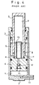
- Japanese Utility Model Laid-Open No. 56-40211 discloses a hydraulic cylinder as shown in Fig. 4, in which a bottom 2 and a cap 3 are provided at both end portions of a cylinder 1, a piston 4 is inserted movably into the cylinder 1, a hollow piston rod 5 is also inserted movably into the cylinder 1 through the cap 3, the piston 4 defines a rod-side oil chamber 6 and a piston-side oil chamber 7 within the cylinder 1, the rod-side oil chamber 6 being in communication with a reservoir 9 in the piston rod 5 through an oil hole 8 formed in the lower portion of the piston rod 5, a pipe 10 extending into the reservoir 9 is mounted upright on the upper end portion of the piston 4, a check valve 12 for opening and closing the reservoir 9 and the piston-side oil chamber 7 is disposed in a through hole 11 formed in the piston 4, and the piston-side oil chamber 7 communicates selectively with a pump or a tank through an oil passage 13.
- a recess 14 is formed in the upper end of the piston 4, the lower end of the piston rod 5 is threadedly engaged with the inner periphery of the recess 14, and within the recess 14 the lower end of the pipe 10 is welded centrally to the upper end of the piston 4.
- a hydraulic cylinder wherein a bottom is provided at one end of a cylinder, a cap is provided at the opposite end of the cylinder, a hollow piston is inserted movably into the cylinder, a piston rod is also inserted movably into the cylinder through said cap, said piston defines a rod-side oil chamber and a piston-side oil chamber within the cylinder, said rod-side oil chamber communicating with a reservoir in said piston rod through an oil hole formed in the lower portion of the piston rod, a pipe extending into said reservoir is mounted upright on the upper end portion of the piston, a relief valve for opening and closing an oil passage between said reservoir and said piston-side oil chamber is disposed in the hollow portion of the piston, and said piston-side oil chamber is selectively connectable with a pump or a tank, characterized in that a spigot portion is mounted upright integrally in the center of the upper end portion of the piston, the base end of said piston rod is fitted on the outer periphery of said spigot portion, another oil
- the present invention provides a hydraulic cylinder suitable for use in a fork lift or the like and capable of dispensing with the pipe welding work to improve the pipe mounting performance and prevent contamination caused by welding, and free from waste of oil.
- a hollow oil bore rod is mounted upright integrally in the center of the upper end of said bottom, and a cushion ring is provided on the inner periphery of the lower hollow portion of the piston so as to be fitted on the outer periphery of said oil bore rod.
- This provides a cushioning effect during compression.
- a snap ring is interposed between the outer periphery of the spigot portion and the inner periphery of the base end of the piston rod, and the outer periphery of the upper end of the spigot portion is tapered in a conical shape.
- the relief valve may be disposed at a lower portion of the hollow portion of the piston or within the hollow portion of the spigot portion.
- the cushion ring serves also as a check valve for opening and closing the piston-side oil chamber and the hollow portion of the piston.
- Figs. 1 and 2 illustrate a hydraulic cylinder according to an embodiment of the present invention.
- a bottom 15 is provided at one end of a cylinder 14 and a cap 27 is provided at the opposite end of the cylinder.
- a piston 17 movably and is also inserted a piston rod 18 movably through a bearing 16 disposed within the cap 27.
- the piston 17 defines a rod-side oil chamber 19 and a piston-side oil chamber 20 within the cylinder 14.
- Through an oil hole 21 formed in the lower portion of the piston rod 18 the rod-side oil chamber 19 is in communication with a reservoir 22 formed within the piston rod 18.
- a relief valve 24 which can open and close to open and close the reservoir 22 and the piston-side oil chamber 20. Further, the piston-side oil chamber 20 is brought into communication selectively with a pump or a tank through an external change-over valve and through oil paths 25 and 26 formed in the bottom 15.
- the cap 27 is connected to the upper end portion of the cylinder 14 through threads and seal.
- the bearing 16 In the inner periphery of the cap 27 are provided the bearing 16, an oil seal 29 and a dust seal 30 to guide the piston rod 18.
- the piston 17 comprises a piston body 33.
- a spigot portion 34 is mounted upright integrally in the center of the upper end of the piston body 33.
- An axial hollow portion is formed as the oil passage 23 centrally of both piston body 33 and spigot portion 34.
- a hollow valve housing 35 is fixed to the lower hollow portion of the piston 17, that is, to the inner periphery of the piston body 33, through a seal and retaining means.
- the valve housing 35 is formed with a stepped portion on the upper portion of its inner periphery side.
- the relief valve 24 which comprises a valve body 36 and a spring for urging the valve body 36 toward the said stepped portion side.
- the lower portion of the piston rod is formed in a cylindrical shape, and the inner periphery of the lower, cylindrical base end portion of the piston rod is fitted on the outer periphery of the spigot portion 34.
- Opposed grooves are formed between the outer periphery of the spigot portion 34 and a base-end recess 18a of the piston rod 18 which defines the reservoir 22, and a snap ring 37 or any other retaining means is fitted in the said grooves to fix the base end of the piston rod 18 to the spigot portion 34.
- the outer periphery of the upper end of the spigot portion 34 is conically tapered as indicated at 38.
- the snap ring 37 is fitted beforehand in the groove of the piston rod 18 and then the base end of the piston rod 18 is fitted forcibly downward onto the spigot portion 34, whereby the snap ring 37 is guided by the taper 38 and can be brought into engagement into the groove formed in the outer periphery of the spigot portion 34 while expanding its diameter smoothly.
- a throttle hole 39 which is in communication with an oil path 40 formed in the spigot portion 34.
- the lower portion of the rod-side oil chamber 19 is in communication with the reservoir 22 through the throttle hole 39 and the oil path 40.
- the upper oil hole 21 formed in the piston rod 18 provides communication between the rod-side oil chamber 19 and the reservoir 22. Besides, when the oil hole 21 is closed by the bearing 16 with extension of the piston rod, the oil hole 21 brings about a throttling effect for the flow from the rod-side oil chamber 19 to the reservoir 22.
- the throttle hole 39 causes the oil in the rod-side oil chamber 19 to flow out into the reservoir 22 while throttling it even when the oil hole 21 is closed with the bearing 16, thereby permitting the piston 17 to move up to its fully extended state in which the piston is in abutment with the cap 27.
- a pipe 41 is fitted upright in the upper end portion of the inner periphery of the spigot portion 34.
- the amount of oil in the rod-side oil chamber 19 necessary for cushioning is controlled, in other words, the oil level is controlled to above the upper end of the oil hole 21.
- the lower portion of the pipe 41 is press-fitted into the hollow portion of the spigot portion 34 along the inner periphery of the spigot portion until a stepped portion formed on the outer periphery of the pipe 41 is retained by the upper end of the spigot portion 34.
- the center of the pipe 41 provides communication between the reservoir 22 and the oil passage 23.
- the above-mentioned hydraulic cylinder constructed as above is attached to a fork lift to raise and lower goods.
- a high-pressure oil is fed to the piston-side oil chamber 20
- both piston 17 and piston rod 18 rise, so that goods supported by an outer end of the piston rod 18 move upward.
- the upper oil hole 21 is throttled gradually by the bearing 16 and the oil in the rod-side oil chamber 19 flows out into the reservoir 22 through the throttled oil path, so that cushioning takes effect gradually.
- the piston 17 can extend up to its abutment with the cap 27 because the lower throttle hole 39 is open.
- the piston-side oil chamber 20 is connected to a tank through a change-over valve. In this case, the goods or the piston rod 18 descends to its most compressed position due to its own weight.
- Fig. 3 illustrates a hydraulic cylinder according to another embodiment of the present invention.
- a cushion ring 42 is provided in the lower inner periphery portion of a piston 17, an oil bore rod 53 is mounted upright in the upper end of a bottom 15, and a relief valve 24 is disposed on the inner periphery side of the spigot portion 34, allowing a cushioning effect to be exhibited during compression by means of both cushion ring 42 and oil bore rod 53.
- the other points relating to structure, function and effect are the same as in the hydraulic cylinder of the previous embodiment illustrated in Fig. 1. Therefore, the same structural portions are indicated by the same reference numerals as in Fig. 1 and detailed explanations thereof are here omitted.
- the piston 17 comprises a piston body 33.
- a hollow spigot portion 34 is mounted upright in the center of the upper end of the piston body 33, and a valve housing 35 is fitted in the spigot portion 34 along the inner periphery of the spigot portion 34.
- the relief valve 24 is inserted into the valve housing 35 in a vertically movable manner to open and close an oil passage 23 as in the embodiment illustrated in Fig. 1.
- the cushion ring 42 which is cylindrical and movable axially thereof.
- the cushion ring 42 is movable into abutment with and away from a stepped upper end portion 43 of the said large-diameter portion.
- a cut-out 42a is formed axially in the outer periphery of the cushion ring 42. As the cushion ring 42 moves downward in the figure, a passage 26 is brought in communication with a piston-side oil chamber 20 through the cut-out 42a.
- the cushion ring 42 has an annular groove formed in the outer periphery thereof.
- a support rod 44 is inserted sideways into the piston body 33 and the front end thereof is engaged with the said annular groove, whereby the cushion ring is supported vertically movably.
- the cylindrical oil bore rod 53 is mounted upright in the center of the upper end of the bottom 15, and in the vicinity of the most compressed state the cushion ring 42 is fitted on the outer periphery of the oil bore rod 53. More specifically, when a high-pressure oil is introduced into the oil passage 26, the high-pressure oil pushes open the cushion ring 42 downward and is introduced into the piston-side oil chamber 20 through the clearance between the cushion ring and the stepped portion 43 and through the cut-out 42a, whereby the piston 17 and the piston rod 18 are extended in the same manner as in Fig. 1.
- the cushion ring 42 is fitted on the outer periphery of the oil bore rod 53.
- the cushion ring 42 is in abutment with the stepped portion 43 and is closed because it is pushed upward by virtue of the internal pressure of the piston-side oil chamber 20, so that the oil in the piston-side oil chamber 20 flows out to the oil passage 26 side through the clearance between the outer periphery of the oil bore rod 53 and the inner periphery of the cushion ring 42.
- the resulting flow resistance affords a cushioning effect.
Landscapes
- Engineering & Computer Science (AREA)
- Physics & Mathematics (AREA)
- Fluid Mechanics (AREA)
- Mechanical Engineering (AREA)
- General Engineering & Computer Science (AREA)
- Actuator (AREA)
- Fluid-Damping Devices (AREA)
Claims (6)
- Cylindre hydraulique dans lequel un fond (15) est disposé à une extrémité d'un cylindre (14), un chapeau (27) est disposé à l'extrémité opposée du cylindre (14), un piston creux (17) est inséré de manière déplaçable dans le cylindre (14), une tige de piston (18) est également insérée de manière déplaçable dans le piston (14) à travers ledit chapeau (27), ledit piston (17) définit une chambre d'huile côté tige (19) et une chambre d'huile côté piston (20) à l'intérieur du cylindre (14), ladite chambre d'huile côté tige (19) communiquant avec un réservoir (22) dans ladite tige de piston (18) à travers un trou d'huile (21) formé dans la partie inférieure de la tige de piston (18), un tuyau (41) s'étendant dans ledit réservoir (22) est monté à la verticale sur la partie d'extrémité supérieure du piston (17), une soupape de décharge (24) pour ouvrir et fermer un passage d'huile (23) entre ledit réservoir (22) et ladite chambre d'huile côté piston (20) est disposé dans la partie creuse du piston (17), et ladite chambre d'huile côté piston (20) est connectable de manière sélective à une pompe ou à un réservoir,
caractérisé en ce qu'une partie de goujon (34) est montée à la verticale intégralement dans le centre de la partie d'extrémité supérieure du piston (17), l'extrémité de base de ladite tige de piston (18) est ajustée sur la périphérie externe de ladite partie de goujon (34), un autre trajet d'huile (40) qui assure la communication entre ladite chambre d'huile côté tige (19) et ledit réservoir (22) est formé au voisinage de la partie d'extrémité inférieure de la tige de piston (18) et dans la partie de goujon (34), et la périphérie externe de l'extrémité de base de ladite conduite (41) est ajustée avec serrage sur une partie supérieure de la partie creuse de la partie de goujon (34). - Cylindre hydraulique selon la revendication 1, dans lequel une tige de sonde d'huile creuse (53) est montée à la verticale intégralement au centre de l'extrémité supérieure dudit fond (15), et une bague d'amortissement (42) est disposée sur la périphérie interne de la partie creuse inférieure du piston (17) de façon à être ajustée sur la périphérie externe de ladite tige de sonde d'huile (53).
- Cylindre hydraulique selon la revendication 1 ou 2, dans lequel un circlip (37) est interposé entre la périphérie externe de ladite partie de goujon (34) et la périphérie interne de l'extrémité de base de ladite tige de piston (18), et la périphérie externe de l'extrémité supérieure de ladite partie de goujon (34) est effilée sous forme conique.
- Cylindre hydraulique selon la revendication 1, dans lequel ladite soupape de décharge (24) est disposée au niveau d'une partie inférieure de la partie creuse dudit piston (17).
- Cylindre hydraulique selon la revendication 1, dans lequel ladite soupape de décharge (24) est disposée à l'intérieur de la partie creuse de ladite partie de goujon (34).
- Cylindre hydraulique selon la revendication 2, dans lequel ladite bague d'amortissement (42) sert également de soupape de non-retour pour ouvrir et fermer à la fois ladite chambre d'huile côté piston (20) et la partie creuse dudit piston (17).
Priority Applications (5)
| Application Number | Priority Date | Filing Date | Title |
|---|---|---|---|
| JP8297827A JPH10122205A (ja) | 1996-10-21 | 1996-10-21 | 油圧シリンダ |
| US08/953,391 US5960696A (en) | 1996-10-21 | 1997-10-17 | Hydraulic cylinder with press-fitted pipe |
| DE69819681T DE69819681T2 (de) | 1996-10-21 | 1998-04-07 | Hydraulikzylinder |
| EP98302705A EP0949423B1 (fr) | 1996-10-21 | 1998-04-07 | Vérin hydraulique |
| ES98302705T ES2210669T3 (es) | 1996-10-21 | 1998-04-07 | Cilindro hidraulico. |
Applications Claiming Priority (2)
| Application Number | Priority Date | Filing Date | Title |
|---|---|---|---|
| JP8297827A JPH10122205A (ja) | 1996-10-21 | 1996-10-21 | 油圧シリンダ |
| EP98302705A EP0949423B1 (fr) | 1996-10-21 | 1998-04-07 | Vérin hydraulique |
Publications (2)
| Publication Number | Publication Date |
|---|---|
| EP0949423A1 EP0949423A1 (fr) | 1999-10-13 |
| EP0949423B1 true EP0949423B1 (fr) | 2003-11-12 |
Family
ID=26151203
Family Applications (1)
| Application Number | Title | Priority Date | Filing Date |
|---|---|---|---|
| EP98302705A Expired - Lifetime EP0949423B1 (fr) | 1996-10-21 | 1998-04-07 | Vérin hydraulique |
Country Status (5)
| Country | Link |
|---|---|
| US (1) | US5960696A (fr) |
| EP (1) | EP0949423B1 (fr) |
| JP (1) | JPH10122205A (fr) |
| DE (1) | DE69819681T2 (fr) |
| ES (1) | ES2210669T3 (fr) |
Families Citing this family (12)
| Publication number | Priority date | Publication date | Assignee | Title |
|---|---|---|---|---|
| JP4262879B2 (ja) * | 2000-10-10 | 2009-05-13 | カヤバ工業株式会社 | リフトシリンダ |
| TW467207U (en) * | 2001-05-11 | 2001-12-01 | Ming-He Chen | Improved buffering structure for terminal stroke of hydraulic cylinder |
| JP4641674B2 (ja) * | 2001-07-10 | 2011-03-02 | カヤバ工業株式会社 | 油圧シリンダ |
| ITPC20060036A1 (it) * | 2006-09-06 | 2008-03-07 | Lift Tek Elecar Srl | Cilindro oleodinamico di sollevamento a tenuta, con recupero interno dell'olio |
| JP5323566B2 (ja) * | 2009-04-02 | 2013-10-23 | カヤバ工業株式会社 | 液圧シリンダ |
| JP5438435B2 (ja) | 2009-08-26 | 2014-03-12 | カヤバ工業株式会社 | 液圧シリンダ |
| JP5429830B2 (ja) * | 2012-03-26 | 2014-02-26 | 株式会社伊丹精機 | リフトシリンダ及びそれを備えたフォークリフト |
| JP5876855B2 (ja) * | 2013-07-05 | 2016-03-02 | Kyb株式会社 | 流体圧シリンダ |
| CN103511389B (zh) * | 2013-10-15 | 2015-07-15 | 湖南特力液压有限公司 | 单作用液压缸 |
| US9926178B2 (en) | 2014-08-20 | 2018-03-27 | Crown Equipment Corporation | Actuator in a lift truck |
| NO20150966A1 (en) * | 2015-07-24 | 2017-01-25 | Macgregor Norway As | Hydraulic actuator |
| CN114876906A (zh) * | 2022-04-25 | 2022-08-09 | 河北裕隆机械有限责任公司 | 一种双杆双作用液压缸 |
Family Cites Families (11)
| Publication number | Priority date | Publication date | Assignee | Title |
|---|---|---|---|---|
| US2974636A (en) * | 1960-05-10 | 1961-03-14 | Cascade Mfg Co | Single-acting ram with fluid relief means |
| FR1356328A (fr) * | 1963-02-11 | 1964-03-27 | Westinghouse Freins & Signaux | Vérin à rappel pneumatique, notamment pour appareil percuteur |
| US3257912A (en) * | 1963-12-30 | 1966-06-28 | Floyd K Haskell | Force amplifier |
| US3259026A (en) * | 1964-11-05 | 1966-07-05 | Parker Hannifin Corp | Fluid pressure motor with unloading valve |
| US3835753A (en) * | 1972-09-19 | 1974-09-17 | A Bunyard | Air cylinder |
| US4065112A (en) * | 1976-08-23 | 1977-12-27 | Towmotor Corporation | Hydraulic jack cushioning apparatus |
| SU844839A1 (ru) * | 1978-06-14 | 1981-07-07 | Предприятие П/Я М-5016 | Гидроцилиндр |
| DE2838978C3 (de) * | 1978-09-07 | 1981-07-09 | Brocke, Adolf, 5810 Witten | Druckmittelbetriebener Arbeitszylinder mit Endlagendämpfung |
| CN1008201B (zh) * | 1985-02-28 | 1990-05-30 | 株式会社丰田自动织机制作所 | 具有缓冲流量控制阀装置的液压操作缸 |
| SE463778B (sv) * | 1989-05-24 | 1991-01-21 | Mecman Ab | Kolv- och daemptaetningsanordning vid en tryckmedie cylinder |
| US5314172A (en) * | 1992-05-08 | 1994-05-24 | Wallis Bernard J | High pressure die cylinder and manifold system |
-
1996
- 1996-10-21 JP JP8297827A patent/JPH10122205A/ja active Pending
-
1997
- 1997-10-17 US US08/953,391 patent/US5960696A/en not_active Expired - Lifetime
-
1998
- 1998-04-07 ES ES98302705T patent/ES2210669T3/es not_active Expired - Lifetime
- 1998-04-07 DE DE69819681T patent/DE69819681T2/de not_active Expired - Lifetime
- 1998-04-07 EP EP98302705A patent/EP0949423B1/fr not_active Expired - Lifetime
Also Published As
| Publication number | Publication date |
|---|---|
| DE69819681T2 (de) | 2004-09-16 |
| JPH10122205A (ja) | 1998-05-12 |
| US5960696A (en) | 1999-10-05 |
| ES2210669T3 (es) | 2004-07-01 |
| EP0949423A1 (fr) | 1999-10-13 |
| DE69819681D1 (de) | 2003-12-18 |
Similar Documents
| Publication | Publication Date | Title |
|---|---|---|
| EP0949423B1 (fr) | Vérin hydraulique | |
| CA1280451C (fr) | Ressort pneumatique autonome interchangeable avec un ressort heliocidal | |
| US5988655A (en) | Vehicular height adjusting device | |
| US6918605B2 (en) | Inverted type front fork in two-wheeled vehicle or the like | |
| JP5323566B2 (ja) | 液圧シリンダ | |
| US4706781A (en) | Fluid-operated cylinder with cushioning flow rate control valve means | |
| EP2330314B1 (fr) | Fourche avant | |
| US20080230335A1 (en) | Front fork | |
| US6234505B1 (en) | Front fork | |
| US7025184B2 (en) | Hydraulic shock absorber with self leveling function for vehicle height | |
| EP1260479A2 (fr) | Vérin amorti | |
| US5028037A (en) | Automatic lifting apparatus | |
| CN213007477U (zh) | 一种多功能液气悬挂装置 | |
| JP5443038B2 (ja) | 液圧シリンダ | |
| JP3748167B2 (ja) | 油圧シリンダ | |
| US4386686A (en) | Hydraulic shock absorber | |
| US6283008B1 (en) | Shock-proof hydraulic cylinder | |
| US3887174A (en) | Shock absorber and leveler unit | |
| JPH09235096A (ja) | 産業車両におけるリフトシリンダ | |
| JPH0710086Y2 (ja) | 単動型油圧シリンダ装置 | |
| CN220667962U (zh) | 活塞式蓄存器 | |
| JPH112281A (ja) | 油圧緩衝器 | |
| JPH0459600A (ja) | リフトシリンダのクッション機構 | |
| JPH0741925Y2 (ja) | 油圧シリンダ | |
| KR20050093179A (ko) | 차고 조정식 쇽업소버 |
Legal Events
| Date | Code | Title | Description |
|---|---|---|---|
| PUAI | Public reference made under article 153(3) epc to a published international application that has entered the european phase |
Free format text: ORIGINAL CODE: 0009012 |
|
| AK | Designated contracting states |
Kind code of ref document: A1 Designated state(s): DE ES FR GB NL |
|
| AX | Request for extension of the european patent |
Free format text: AL;LT;LV;MK;RO;SI |
|
| 17P | Request for examination filed |
Effective date: 20000317 |
|
| AKX | Designation fees paid |
Free format text: DE ES FR GB NL |
|
| 17Q | First examination report despatched |
Effective date: 20021017 |
|
| GRAH | Despatch of communication of intention to grant a patent |
Free format text: ORIGINAL CODE: EPIDOS IGRA |
|
| GRAS | Grant fee paid |
Free format text: ORIGINAL CODE: EPIDOSNIGR3 |
|
| GRAA | (expected) grant |
Free format text: ORIGINAL CODE: 0009210 |
|
| AK | Designated contracting states |
Kind code of ref document: B1 Designated state(s): DE ES FR GB NL |
|
| REG | Reference to a national code |
Ref country code: GB Ref legal event code: FG4D |
|
| REF | Corresponds to: |
Ref document number: 69819681 Country of ref document: DE Date of ref document: 20031218 Kind code of ref document: P |
|
| REG | Reference to a national code |
Ref country code: ES Ref legal event code: FG2A Ref document number: 2210669 Country of ref document: ES Kind code of ref document: T3 |
|
| ET | Fr: translation filed | ||
| PLBE | No opposition filed within time limit |
Free format text: ORIGINAL CODE: 0009261 |
|
| STAA | Information on the status of an ep patent application or granted ep patent |
Free format text: STATUS: NO OPPOSITION FILED WITHIN TIME LIMIT |
|
| 26N | No opposition filed |
Effective date: 20040813 |
|
| PGFP | Annual fee paid to national office [announced via postgrant information from national office to epo] |
Ref country code: DE Payment date: 20110330 Year of fee payment: 14 |
|
| PGFP | Annual fee paid to national office [announced via postgrant information from national office to epo] |
Ref country code: GB Payment date: 20110406 Year of fee payment: 14 |
|
| GBPC | Gb: european patent ceased through non-payment of renewal fee |
Effective date: 20120407 |
|
| PG25 | Lapsed in a contracting state [announced via postgrant information from national office to epo] |
Ref country code: GB Free format text: LAPSE BECAUSE OF NON-PAYMENT OF DUE FEES Effective date: 20120407 |
|
| REG | Reference to a national code |
Ref country code: DE Ref legal event code: R119 Ref document number: 69819681 Country of ref document: DE Effective date: 20121101 |
|
| PGFP | Annual fee paid to national office [announced via postgrant information from national office to epo] |
Ref country code: ES Payment date: 20140311 Year of fee payment: 17 |
|
| PGFP | Annual fee paid to national office [announced via postgrant information from national office to epo] |
Ref country code: FR Payment date: 20140409 Year of fee payment: 17 Ref country code: NL Payment date: 20140308 Year of fee payment: 17 |
|
| PG25 | Lapsed in a contracting state [announced via postgrant information from national office to epo] |
Ref country code: DE Free format text: LAPSE BECAUSE OF NON-PAYMENT OF DUE FEES Effective date: 20121101 |
|
| REG | Reference to a national code |
Ref country code: NL Ref legal event code: MM Effective date: 20150501 |
|
| REG | Reference to a national code |
Ref country code: FR Ref legal event code: ST Effective date: 20151231 |
|
| PG25 | Lapsed in a contracting state [announced via postgrant information from national office to epo] |
Ref country code: FR Free format text: LAPSE BECAUSE OF NON-PAYMENT OF DUE FEES Effective date: 20150430 |
|
| PG25 | Lapsed in a contracting state [announced via postgrant information from national office to epo] |
Ref country code: NL Free format text: LAPSE BECAUSE OF NON-PAYMENT OF DUE FEES Effective date: 20150501 |
|
| REG | Reference to a national code |
Ref country code: ES Ref legal event code: FD2A Effective date: 20160526 |
|
| PG25 | Lapsed in a contracting state [announced via postgrant information from national office to epo] |
Ref country code: ES Free format text: LAPSE BECAUSE OF NON-PAYMENT OF DUE FEES Effective date: 20150408 |