EP0949708A2 - Module - Google Patents
Module Download PDFInfo
- Publication number
- EP0949708A2 EP0949708A2 EP99105234A EP99105234A EP0949708A2 EP 0949708 A2 EP0949708 A2 EP 0949708A2 EP 99105234 A EP99105234 A EP 99105234A EP 99105234 A EP99105234 A EP 99105234A EP 0949708 A2 EP0949708 A2 EP 0949708A2
- Authority
- EP
- European Patent Office
- Prior art keywords
- module
- support frame
- radio
- antenna
- wall
- Prior art date
- Legal status (The legal status is an assumption and is not a legal conclusion. Google has not performed a legal analysis and makes no representation as to the accuracy of the status listed.)
- Granted
Links
- 230000005855 radiation Effects 0.000 abstract description 2
- 238000009434 installation Methods 0.000 description 13
- 238000010586 diagram Methods 0.000 description 3
- 230000004048 modification Effects 0.000 description 3
- 238000012986 modification Methods 0.000 description 3
- 238000005516 engineering process Methods 0.000 description 2
- 239000002184 metal Substances 0.000 description 2
- 239000011505 plaster Substances 0.000 description 2
- 238000004378 air conditioning Methods 0.000 description 1
- 230000005540 biological transmission Effects 0.000 description 1
- 230000001419 dependent effect Effects 0.000 description 1
- 238000011161 development Methods 0.000 description 1
- 230000018109 developmental process Effects 0.000 description 1
- 230000000694 effects Effects 0.000 description 1
- 238000010616 electrical installation Methods 0.000 description 1
- 239000011521 glass Substances 0.000 description 1
- 238000010438 heat treatment Methods 0.000 description 1
- 230000010354 integration Effects 0.000 description 1
- 239000000463 material Substances 0.000 description 1
- 239000012811 non-conductive material Substances 0.000 description 1
- 230000008520 organization Effects 0.000 description 1
- 238000009423 ventilation Methods 0.000 description 1
- 238000005406 washing Methods 0.000 description 1
- XLYOFNOQVPJJNP-UHFFFAOYSA-N water Substances O XLYOFNOQVPJJNP-UHFFFAOYSA-N 0.000 description 1
Images
Classifications
-
- H—ELECTRICITY
- H01—ELECTRIC ELEMENTS
- H01Q—ANTENNAS, i.e. RADIO AERIALS
- H01Q1/00—Details of, or arrangements associated with, antennas
- H01Q1/44—Details of, or arrangements associated with, antennas using equipment having another main function to serve additionally as an antenna, e.g. means for giving an antenna an aesthetic aspect
-
- H—ELECTRICITY
- H01—ELECTRIC ELEMENTS
- H01Q—ANTENNAS, i.e. RADIO AERIALS
- H01Q1/00—Details of, or arrangements associated with, antennas
- H01Q1/12—Supports; Mounting means
- H01Q1/22—Supports; Mounting means by structural association with other equipment or articles
Definitions
- the invention is based on the genus, as in independent claim 1 specified.
- radio modules are already used for radio alarm systems such as radio contact detectors, radio glass break detectors, etc. in the Trade.
- An intrusion alarm system can be part of a home automation system be.
- a home automation system connects technical functions with household applications. For this include, for example, security technology, the Heating, ventilation and air conditioning control, the lighting and Blind control and load management.
- the domotics in the house are constantly being expanded. That is part of it the control of the stove, the washing machine, the Roller shutter control, the control of the garage door, the Remote inquiry of the gas or water meter, for example etc.
- the domotic is as device and cross-application system designed that all in House or apartment existing individual components and Applications integrated into one system.
- the data exchange between sensors, actuators and a control center thereby via the so-called European installation bus (EIB) of the European Installation Bus Association (EIBA), an organization in which the leading European Electrical installation companies have merged.
- EIB European installation bus
- EIBA European Installation Bus Association
- a low-loss transmission of radio signals in the Environment of a module installed under plaster thereby achieved that the support frame of the module or parts of the support frame designed as an element of a radio antenna are.
- the sending and receiving of electromagnetic waves the flush-mounted installation of a module is made possible by the use of the support frame as an antenna element effective charisma.
- the radio antenna has a directional diagram, so that the lossy radiation of energy into the wall is reduced.
- the antenna can be made robust, so that they face the harsh conditions of the installation craft justice. For the user of the installation technology the antenna is invisible.
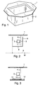
- FIG. 1 shows only one of a module according to the invention metallic, flange-like support frame 1, which is not on mechanically with a Insulated container 2 is connected to the recording an electrical circuit arrangement is suitable, the is the main component of such a module.
- a module is used in an actuator or a sensor usually contain a circuit board.
- the Support frame is designed so that its bottom at Flush mounting from the outside rests on a wall, while the insulating container 2 in a Installation recess immersed in the wall, the Installation recess lined with a mounting box can.
- the supporting frame 1 is over an electrical line 4 with a transmitter or receiver 3 connected.
- the support frame 1 acts as Element of a radio antenna, i.e. Broadcast and / or Receiving antenna.
- Either the sender or receiver can use a electrical line 5 with an electrically conductive Side covering 6 of the shown in Figure 1 Isolierstoff mattersers 2 be connected; then this works Side covering as another antenna element.
- the transmitter or receiver 3 can with an electrical line 7 an electrically conductive floor covering 8 of Isolierstoff variousers 2 ( Figure 1) connected, then the floor covering acts as a further antenna element. It can but also the floor with the side covering electrically be connected; then one of the lines 5, 7 is sufficient.
- a further antenna element 9 can optionally be provided, either in the depth of the wall or on the other side of the wall.
- This Antenna element 9 can also act as a reflector. Depending on Which function it should take over, it can with Earth potential and / or with one or both of the coverings 6, 8 be connected.
- the modification shown in Figure 3 shows a case in which the transmitter or receiver 3 over an electrical line 10 with a covering 11 on a Printed circuit board 12 is connected.
- the covering 11 acts as second antenna element.
- the circuit board 12 is located with or without an insulating container (2 in Figure 1) in a recess in a wall.
- the support frame 1 can also consist of several parts exist that are electrically isolated from each other and each form an element of the radio antenna; at two Sharing then lists one for each of the parts different high-frequency potential and / or different high-frequency phase electrical Line of the transmitter or receiver 3.
- On the support frame can connect a high frequency circuit directly or connected capacitively or inductively.
Landscapes
- Support Of Aerials (AREA)
- Selective Calling Equipment (AREA)
- Near-Field Transmission Systems (AREA)
- Structure Of Receivers (AREA)
Applications Claiming Priority (2)
| Application Number | Priority Date | Filing Date | Title |
|---|---|---|---|
| DE19815986A DE19815986A1 (de) | 1998-04-09 | 1998-04-09 | Modul |
| DE19815986 | 1998-04-09 |
Publications (3)
| Publication Number | Publication Date |
|---|---|
| EP0949708A2 true EP0949708A2 (fr) | 1999-10-13 |
| EP0949708A3 EP0949708A3 (fr) | 2001-06-13 |
| EP0949708B1 EP0949708B1 (fr) | 2005-06-29 |
Family
ID=7864147
Family Applications (1)
| Application Number | Title | Priority Date | Filing Date |
|---|---|---|---|
| EP99105234A Expired - Lifetime EP0949708B1 (fr) | 1998-04-09 | 1999-03-13 | Module |
Country Status (2)
| Country | Link |
|---|---|
| EP (1) | EP0949708B1 (fr) |
| DE (2) | DE19815986A1 (fr) |
Families Citing this family (3)
| Publication number | Priority date | Publication date | Assignee | Title |
|---|---|---|---|---|
| DE29913500U1 (de) | 1999-08-03 | 1999-12-16 | Siemens AG, 80333 München | Installationsgerät mit Funkantenne |
| DE10125913B4 (de) * | 2001-05-28 | 2005-03-17 | Siemens Ag | Installationseinheit |
| DE102004057515B4 (de) * | 2004-11-29 | 2017-10-12 | Tridonic Gmbh & Co Kg | Lampenbetriebsgerät mit Schnittstelleneinheit zum drahtlosen Empfangen externer Steuersignale |
Family Cites Families (4)
| Publication number | Priority date | Publication date | Assignee | Title |
|---|---|---|---|---|
| US5298894A (en) * | 1992-06-17 | 1994-03-29 | Badger Meter, Inc. | Utility meter transponder/antenna assembly for underground installations |
| DE4411290C2 (de) * | 1994-03-31 | 1997-02-27 | Dorma Gmbh & Co Kg | Vorrichtung zur Aufnahme eines Sensors |
| JPH10292702A (ja) * | 1997-04-21 | 1998-11-04 | Aisin Seiki Co Ltd | ドア近接通信装置およびドアロック制御装置 |
| DE19812185C1 (de) * | 1998-03-19 | 1999-08-26 | Honeywell Ag | Installationseinheit |
-
1998
- 1998-04-09 DE DE19815986A patent/DE19815986A1/de not_active Withdrawn
-
1999
- 1999-03-13 EP EP99105234A patent/EP0949708B1/fr not_active Expired - Lifetime
- 1999-03-13 DE DE59912207T patent/DE59912207D1/de not_active Expired - Lifetime
Also Published As
| Publication number | Publication date |
|---|---|
| EP0949708A3 (fr) | 2001-06-13 |
| DE19815986A1 (de) | 1999-10-14 |
| DE59912207D1 (de) | 2005-08-04 |
| EP0949708B1 (fr) | 2005-06-29 |
Similar Documents
| Publication | Publication Date | Title |
|---|---|---|
| EP0836732B1 (fr) | Systeme de mesure de consommation pour releve a distance | |
| EP1646156B1 (fr) | Système de transmission de messages reposant sur l'utilisation d'un champ électrique proche | |
| EP1228578A1 (fr) | Systeme de communication, notamment pour zone interieure | |
| EP3186862B1 (fr) | Module d'automatisation pour la domotique | |
| DE102019214390A1 (de) | Antenne für eine Basisstation eines drahtlosen Fernsteuerystems | |
| DE19654837A1 (de) | Bussystem für die Fernsteuerung, Programmierung und Überwachung von elektrischen Geräten in Versorgungsanlagen mit Verwendung der Niederspannungsleitungen für die Datenübertragung und Koppelmodul für den Anschluß der elektrischen Geräten an dieses Bussystem | |
| EP0949708B1 (fr) | Module | |
| EP0982867B1 (fr) | Module encastrable avec une antenne pivotante | |
| DE19835252C2 (de) | Verfahren und System zur Übermittlung von Daten und/oder Steuerinformationen an eine Empfangsvorrichtung | |
| DE4411290C2 (de) | Vorrichtung zur Aufnahme eines Sensors | |
| DE102007008469A1 (de) | Mess- oder Meldewertübertragungs- und Antenneneinrichtung | |
| DE3623805C2 (de) | Signalübertragungssystem | |
| DE4023457C2 (fr) | ||
| DE19954579C1 (de) | Vorrichtung zur Erfassung des Energieverbrauchs einer Heizungsanlage | |
| AT502978B1 (de) | System zur steuerung elektrischer verbraucher der elektroinstallationstechnik | |
| DE102007059032A1 (de) | Vorrichtung zur automatisierten Erfassung und Weiterleitung der Zählerstände von Verbrauchzählern, insbesondere von Gas-, Strom- und Wasserzählern | |
| DE102009016410A1 (de) | Antennensystem für einen Schließzylinder, welcher das Zylindergehäuse als aktives Antennenelement nutzt | |
| DE102017105196A1 (de) | Steuerungsmodul zur Steuerung elektrischer Geräte | |
| DE29719056U1 (de) | Fernbediente Zirkulationsumwälzpumpe | |
| EP4542111B1 (fr) | Détecteur de mouvement et son utilisation ainsi qu'ensemble comprenant un tel détecteur | |
| DE102007039451A1 (de) | System zur Ortung beweglicher Objekte | |
| WO2011141058A1 (fr) | Système d'antennes pour cylindre à boutons | |
| DE3030739A1 (de) | Gebaeudeleitsystem | |
| CH693655A5 (de) | Regelgeräteeinrichtung für Heizgeräte. | |
| DE19624273A1 (de) | Verbrauchserfassungssystem zur Fernablesung |
Legal Events
| Date | Code | Title | Description |
|---|---|---|---|
| PUAI | Public reference made under article 153(3) epc to a published international application that has entered the european phase |
Free format text: ORIGINAL CODE: 0009012 |
|
| AK | Designated contracting states |
Kind code of ref document: A2 Designated state(s): CH DE ES FR GB IT LI SE |
|
| AX | Request for extension of the european patent |
Free format text: AL;LT;LV;MK;RO;SI |
|
| PUAL | Search report despatched |
Free format text: ORIGINAL CODE: 0009013 |
|
| AK | Designated contracting states |
Kind code of ref document: A3 Designated state(s): AT BE CH CY DE DK ES FI FR GB GR IE IT LI LU MC NL PT SE |
|
| AX | Request for extension of the european patent |
Free format text: AL;LT;LV;MK;RO;SI |
|
| RIC1 | Information provided on ipc code assigned before grant |
Free format text: 7H 01Q 1/44 A, 7H 01Q 1/22 B, 7H 05B 37/02 B |
|
| 17P | Request for examination filed |
Effective date: 20011213 |
|
| AKX | Designation fees paid |
Free format text: CH DE ES FR GB IT LI SE |
|
| 17Q | First examination report despatched |
Effective date: 20020802 |
|
| GRAP | Despatch of communication of intention to grant a patent |
Free format text: ORIGINAL CODE: EPIDOSNIGR1 |
|
| GRAS | Grant fee paid |
Free format text: ORIGINAL CODE: EPIDOSNIGR3 |
|
| GRAA | (expected) grant |
Free format text: ORIGINAL CODE: 0009210 |
|
| AK | Designated contracting states |
Kind code of ref document: B1 Designated state(s): CH DE ES FR GB IT LI SE |
|
| PG25 | Lapsed in a contracting state [announced via postgrant information from national office to epo] |
Ref country code: IT Free format text: LAPSE BECAUSE OF FAILURE TO SUBMIT A TRANSLATION OF THE DESCRIPTION OR TO PAY THE FEE WITHIN THE PRE;WARNING: LAPSES OF ITALIAN PATENTS WITH EFFECTIVE DATE BEFORE 2007 MAY HAVE OCCURRED AT ANY TIME BEFORE 2007. THE CORRECT EFFECTIVE DATE MAY BE DIFFERENT FROM THE ONE RECORDED.SCRIBED TIME-LIMIT Effective date: 20050629 Ref country code: GB Free format text: LAPSE BECAUSE OF FAILURE TO SUBMIT A TRANSLATION OF THE DESCRIPTION OR TO PAY THE FEE WITHIN THE PRESCRIBED TIME-LIMIT Effective date: 20050629 |
|
| REG | Reference to a national code |
Ref country code: GB Ref legal event code: FG4D Free format text: NOT ENGLISH |
|
| REG | Reference to a national code |
Ref country code: CH Ref legal event code: EP |
|
| REF | Corresponds to: |
Ref document number: 59912207 Country of ref document: DE Date of ref document: 20050804 Kind code of ref document: P |
|
| PG25 | Lapsed in a contracting state [announced via postgrant information from national office to epo] |
Ref country code: SE Free format text: LAPSE BECAUSE OF FAILURE TO SUBMIT A TRANSLATION OF THE DESCRIPTION OR TO PAY THE FEE WITHIN THE PRESCRIBED TIME-LIMIT Effective date: 20050929 |
|
| PG25 | Lapsed in a contracting state [announced via postgrant information from national office to epo] |
Ref country code: ES Free format text: LAPSE BECAUSE OF FAILURE TO SUBMIT A TRANSLATION OF THE DESCRIPTION OR TO PAY THE FEE WITHIN THE PRESCRIBED TIME-LIMIT Effective date: 20051010 |
|
| GBV | Gb: ep patent (uk) treated as always having been void in accordance with gb section 77(7)/1977 [no translation filed] |
Effective date: 20050629 |
|
| PG25 | Lapsed in a contracting state [announced via postgrant information from national office to epo] |
Ref country code: LI Free format text: LAPSE BECAUSE OF NON-PAYMENT OF DUE FEES Effective date: 20060331 Ref country code: CH Free format text: LAPSE BECAUSE OF NON-PAYMENT OF DUE FEES Effective date: 20060331 |
|
| PLBE | No opposition filed within time limit |
Free format text: ORIGINAL CODE: 0009261 |
|
| STAA | Information on the status of an ep patent application or granted ep patent |
Free format text: STATUS: NO OPPOSITION FILED WITHIN TIME LIMIT |
|
| 26N | No opposition filed |
Effective date: 20060330 |
|
| EN | Fr: translation not filed | ||
| PG25 | Lapsed in a contracting state [announced via postgrant information from national office to epo] |
Ref country code: FR Free format text: LAPSE BECAUSE OF FAILURE TO SUBMIT A TRANSLATION OF THE DESCRIPTION OR TO PAY THE FEE WITHIN THE PRESCRIBED TIME-LIMIT Effective date: 20060825 |
|
| REG | Reference to a national code |
Ref country code: CH Ref legal event code: PL |
|
| PG25 | Lapsed in a contracting state [announced via postgrant information from national office to epo] |
Ref country code: FR Free format text: LAPSE BECAUSE OF FAILURE TO SUBMIT A TRANSLATION OF THE DESCRIPTION OR TO PAY THE FEE WITHIN THE PRESCRIBED TIME-LIMIT Effective date: 20050629 |
|
| PGFP | Annual fee paid to national office [announced via postgrant information from national office to epo] |
Ref country code: DE Payment date: 20100512 Year of fee payment: 12 |
|
| PG25 | Lapsed in a contracting state [announced via postgrant information from national office to epo] |
Ref country code: DE Free format text: LAPSE BECAUSE OF NON-PAYMENT OF DUE FEES Effective date: 20111001 |
|
| REG | Reference to a national code |
Ref country code: DE Ref legal event code: R119 Ref document number: 59912207 Country of ref document: DE Effective date: 20111001 |