EP0949712A2 - Connecteur de contact à pression - Google Patents
Connecteur de contact à pression Download PDFInfo
- Publication number
- EP0949712A2 EP0949712A2 EP99301882A EP99301882A EP0949712A2 EP 0949712 A2 EP0949712 A2 EP 0949712A2 EP 99301882 A EP99301882 A EP 99301882A EP 99301882 A EP99301882 A EP 99301882A EP 0949712 A2 EP0949712 A2 EP 0949712A2
- Authority
- EP
- European Patent Office
- Prior art keywords
- housing
- protrusions
- outer housing
- inner housing
- inner member
- Prior art date
- Legal status (The legal status is an assumption and is not a legal conclusion. Google has not performed a legal analysis and makes no representation as to the accuracy of the status listed.)
- Withdrawn
Links
Images

Classifications
-
- H—ELECTRICITY
- H01—ELECTRIC ELEMENTS
- H01R—ELECTRICALLY-CONDUCTIVE CONNECTIONS; STRUCTURAL ASSOCIATIONS OF A PLURALITY OF MUTUALLY-INSULATED ELECTRICAL CONNECTING ELEMENTS; COUPLING DEVICES; CURRENT COLLECTORS
- H01R13/00—Details of coupling devices of the kinds covered by groups H01R12/70 or H01R24/00 - H01R33/00
- H01R13/46—Bases; Cases
- H01R13/502—Bases; Cases composed of different pieces
- H01R13/506—Bases; Cases composed of different pieces assembled by snap action of the parts
-
- H—ELECTRICITY
- H01—ELECTRIC ELEMENTS
- H01R—ELECTRICALLY-CONDUCTIVE CONNECTIONS; STRUCTURAL ASSOCIATIONS OF A PLURALITY OF MUTUALLY-INSULATED ELECTRICAL CONNECTING ELEMENTS; COUPLING DEVICES; CURRENT COLLECTORS
- H01R24/00—Two-part coupling devices, or either of their cooperating parts, characterised by their overall structure
- H01R24/28—Coupling parts carrying pins, blades or analogous contacts and secured only to wire or cable
-
- H—ELECTRICITY
- H01—ELECTRIC ELEMENTS
- H01R—ELECTRICALLY-CONDUCTIVE CONNECTIONS; STRUCTURAL ASSOCIATIONS OF A PLURALITY OF MUTUALLY-INSULATED ELECTRICAL CONNECTING ELEMENTS; COUPLING DEVICES; CURRENT COLLECTORS
- H01R13/00—Details of coupling devices of the kinds covered by groups H01R12/70 or H01R24/00 - H01R33/00
- H01R13/64—Means for preventing incorrect coupling
- H01R13/645—Means for preventing incorrect coupling by exchangeable elements on case or base
- H01R13/6456—Means for preventing incorrect coupling by exchangeable elements on case or base comprising keying elements at different positions along the periphery of the connector
-
- H—ELECTRICITY
- H01—ELECTRIC ELEMENTS
- H01R—ELECTRICALLY-CONDUCTIVE CONNECTIONS; STRUCTURAL ASSOCIATIONS OF A PLURALITY OF MUTUALLY-INSULATED ELECTRICAL CONNECTING ELEMENTS; COUPLING DEVICES; CURRENT COLLECTORS
- H01R2107/00—Four or more poles
-
- H—ELECTRICITY
- H01—ELECTRIC ELEMENTS
- H01R—ELECTRICALLY-CONDUCTIVE CONNECTIONS; STRUCTURAL ASSOCIATIONS OF A PLURALITY OF MUTUALLY-INSULATED ELECTRICAL CONNECTING ELEMENTS; COUPLING DEVICES; CURRENT COLLECTORS
- H01R4/00—Electrically-conductive connections between two or more conductive members in direct contact, i.e. touching one another; Means for effecting or maintaining such contact; Electrically-conductive connections having two or more spaced connecting locations for conductors and using contact members penetrating insulation
- H01R4/24—Connections using contact members penetrating or cutting insulation or cable strands
- H01R4/2416—Connections using contact members penetrating or cutting insulation or cable strands the contact members having insulation-cutting edges, e.g. of tuning fork type
- H01R4/2445—Connections using contact members penetrating or cutting insulation or cable strands the contact members having insulation-cutting edges, e.g. of tuning fork type the contact members having additional means acting on the insulation or the wire, e.g. additional insulation penetrating means, strain relief means or wire cutting knives
- H01R4/2466—Connections using contact members penetrating or cutting insulation or cable strands the contact members having insulation-cutting edges, e.g. of tuning fork type the contact members having additional means acting on the insulation or the wire, e.g. additional insulation penetrating means, strain relief means or wire cutting knives the contact members having a channel-shaped part, the opposite sidewalls of which comprise insulation-cutting means
-
- Y—GENERAL TAGGING OF NEW TECHNOLOGICAL DEVELOPMENTS; GENERAL TAGGING OF CROSS-SECTIONAL TECHNOLOGIES SPANNING OVER SEVERAL SECTIONS OF THE IPC; TECHNICAL SUBJECTS COVERED BY FORMER USPC CROSS-REFERENCE ART COLLECTIONS [XRACs] AND DIGESTS
- Y10—TECHNICAL SUBJECTS COVERED BY FORMER USPC
- Y10S—TECHNICAL SUBJECTS COVERED BY FORMER USPC CROSS-REFERENCE ART COLLECTIONS [XRACs] AND DIGESTS
- Y10S439/00—Electrical connectors
- Y10S439/901—Connector hood or shell
- Y10S439/903—Special latch for insert
Definitions
- the present invention relates to a pressure contact electrical connector.
- FIG. 14 of this specification shows an electrical connector as shown in JP-2-148583.
- This connector comprises an outer member 101, and two inner members 102 which are housed within the outer member 101.
- the anterior portion 104 of the outer member 101 is tubular, and terminal housing chambers 103 are formed on the upper posterior side of portion 104 in order to house pressure contact terminal fittings (not shown).
- the two inner members 102 can be housed within the portion 104, and fitting holes 106 are formed on side walls in order to support and maintain the inner members 102, by engagement with protrusions 107.
- Terminal housing chambers 103 capable of housing terminal fittings, are formed also on the inner members 102.
- Locking protrusions 108 protrude from the posterior ends of the two side walls of the inner members 102.
- the connector is provided with a locking member 105 which fits with the locking protrusions 108 and supports the connection of the members 101 and 102.
- Locking holes 109 are formed on this locking member 105, these fitting together with the locking protrusions 108 of the two inner members 102 and the outer member 101.
- the terminal fittings are first housed within each terminal housing chamber 103.
- the inner members 102 are inserted into the attachment member 104. This causes the fitting holes 106 to fit together with the fitting protrusions 107, which fixes the position of the anterior ends of the inner members 102 in an up-down and anterior-posterior direction.
- the locking member 105 is attached from above the outer member 101, this causing the locking holes 109 and the locking protrusions 108 to fit together. This strengthens the connecting force between the two members 101 and 102, and fixes the position of the posterior ends of the inner members 102 in an up-down and anterior-posterior direction.
- Two sets of fitting holes 106 are provided to give temporary and final fitting positions of the inner members 102.
- the present invention has been developed after taking the above problem into consideration, and aims to present a pressure contact connector in which the inner members cannot be inserted upside-down, and in which operability is improved.
- a pressure contact electrical connector comprising a tubular outer housing, and an inner housing insertable therein, said inner housing comprising an inner body adapted to contain pressure contact terminal fittings and a cover latchable to the inner body, wherein the inner housing has protrusions on opposite sides thereof and the outer housing has opposite recesses adapted to receive said protrusions in one respective orientation of said outer housing and inner housing only.
- the protrusions protrude to the exterior and are adapted to be gripped or pinched to permit removal of the inner housing.
- the protrusions also act as a resilient latch for the cover of the inner housing. Separate means of fixing the cover is thus not required, and the moulding can be simplified.
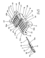
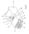
- Figure 1 is a diagonal view of a connector showing an inner member in a joined state prior to being housed within an outer member.
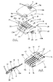
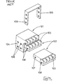
- Figure 2 is a diagonal view showing an upper and a lower inner member in a separated state.
- Figure 3 is a diagonal view showing the upper inner member from the rear side.
- Figure 4 is a diagonal view showing a terminal fitting about to be attached to the upper inner member.
- Figure 5 is a diagonal view showing the lower inner member from the rear side.
- Figure 6 is a diagonal view showing a terminal fitting about to be attached to the lower inner member.
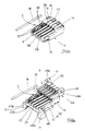
- Figure 7 is a diagonal view showing the inner member with terminal fittings attached and prior to being joined together.
- Figure 8 is a rear side view of the inner member in a joined state.
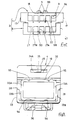
- Figure 9 is a rear side view of the outer member.
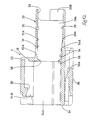
- Figure 10 is a side cross-sectional view of the outer member.
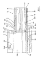
- Figure 11 is a side cross-sectional view of the inner member and the outer member in a joined state (without terminal fittings).
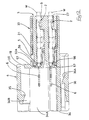
- Figure 12 is a side cross-sectional view of the inner member and the outer member in a joined state.
- Figure 13 is a diagonal view of the connector in which the attachment has been completed.
- Figure 14 is a diagonal view of a prior art connector in a separated state.
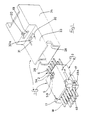
- a pressure contact connector 1 according to the invention comprises an inner member 3 for housing terminal fittings 2, and an outer member 4 which houses the inner member 3.
- the inner member 3 comprises connected upper and lower inner members 7 and 8.
- the 'inner member 3' will refer to both the upper and lower inner members 7 and 8 when these are in a connected state.
- the direction in which stopping protrusions 5 of the inner member 3 protrude will be considered to be the upper side, while the direction in which tabs 6 of the terminal fittings 2 protrude from the inner member 3 will be considered to be the anterior side.
- the terminal fittings 2 are provided on the male side and comprise an electrically conductive metal sheet which has been bent, these joining with corresponding female terminal fittings (not shown). These terminal fittings 2 will be termed pressure contact terminal fittings since they are connected to insulated electric wires W by these being pushed on from above. Tabs 6 protrude from the anterior of the terminal fittings 2, these tabs 6 connecting with the corresponding female terminal fittings. A bendable lance 10 is formed by cutting-away at the posterior of each tab 6. The right edge portion of each lance 10 is folded upwards to form a stopping edge 10A. Furthermore, the left and right side edges of the terminal fitting 2 are folded over to form a pair of side walls 38.
- a wire insertion groove 37 is formed in the space between the pair of side walls 38, the insulated wire W being inserted into this groove 37 on the side from which the lance 10 was cut away.
- a pair of left and right barrels 12 protrude at the posterior of the side walls 38, these crimping the wire W.
- This pair of barrels 12 protrudes from asymmetrical positions relative to one another along the anterior-posterior direction of the terminal fitting 2.
- a pair of pressure contact blades 11 are cut anteriorly and posteriorly into the sides of the groove 37, these blades 11 being located in the centre of the two side walls 38. These blades 11 are symmetrical on each side.
- the groove between the tips of the pressure contact blades 11 is slightly smaller in width than the insulation of the wire W.
- the wire W is pushed in from the open side of the blades 11, which cut into the insulation.
- the core of the wire W makes contact with the pressure contact blade 11, and the wire W and the terminal fitting 2 come into electrical contact.
- the inner member 3 comprises connected upper and lower inner members 7 and 8.
- the upper and lower inner members 7 and 8 are both of moulded plastic, and the interiors thereof house the terminal fittings 2.
- a pair of left and right stopping protrusions 5 protrude from the anterior central portion of the upper face of the inner member 7.
- a jig insertion groove 18, into which a jig (not shown) can be inserted, runs down the centre of these two stopping protrusions 5.
- This jig insertion groove 18 is provided from the anterior edge of the inner member 7, and passes through the stopping protrusions 5 to a location slightly to the posterior thereof.
- a jig is inserted into the groove 18 in order to separate the inner member 3 and the outer member 4 after the pressure contact connector 1 has been assembled.
- Guiding faces 5A are formed on the anterior faces of the stopping protrusions 5
- stopping faces 5B are formed on the posterior faces, these stopping faces 5B being perpendicular with respect to the upper face of the inner member 7.
- Terminal housing chambers 9 for housing the terminal fittings 2 are formed on the lower face of the inner member 7 (see Figure 3). Side walls 40 are formed on the left and right of the inner member 7, and dividing walls 9A are provided at identical distances from one another between these side walls 40. The terminal housing chambers 9 are formed in the divisions between these dividing walls 9A.
- the anterior end of each terminal housing chamber 9 is provided with a cover 39 which covers the lower face thereof and which, from the centre to the posterior, leaves the pushed-in portion of the wire W open.
- the cover 39 connects with the two side walls 40.
- a lance stopping groove 41 is formed in an anterior-posterior direction on the cover 39 at a location corresponding to the right side edge portion of the terminal housing chamber 9, the stopping edge 10A of the terminal fitting 2 fitting into this lance stopping groove 41. Furthermore, as shown in Figure 3, only the left halves of protruding edges of the dividing walls 9A protrude, these forming step-shaped fitting edges 9B. Dovetailed tenons 14 and 42 protrude from the cover 39, these serving as stopping members which hold the inner members 7 and 8 together. The tenons 42 are a left and right pair located towards the central portion of the cover 39.
- these tenons are fan-shaped, while seen cross-sectionally from the front they have a trapezoid shape.
- the tenons 14 are located at the left and right sides of the cover 39. Seen from the anterior and posterior sides of the inner member 7 these tenons are fan-shaped, while seen cross-sectionally from the side they have a trapezoid shape.
- the engagement of the tenons 14 and 42 is thereby strengthened in either the anterior-posterior direction or the left-right direction, and the inner members 7 and 8 are connected in a balanced manner.
- the tenons 14 and 42 are engaged respectively by dovetailed grooves 16 and 43 located on the lower inner members 8.
- stopping claws 15 are formed on the posterior end portion of the left and right side walls 40 by a cut-away portion thereof, the anterior end of each claw 15 being connected with the side wall 40.
- the claws 15 fit with position-fixing protrusions 17 located on the lower side of the inner member 8.
- the upper face of the lower inner member 8 is configured such that it will fit with each terminal housing chamber 9 of the upper inner member 7, and will maintain the terminal fittings 2 in a stable manner.
- the posterior end of the inner member 8 is higher than the central or anterior portions thereof, and dividing-wall housing grooves 22 are formed therein in order to house the fitting edge 9B of the dividing walls 9A.
- Electric wire supporting members 23 protrude at an anterior location from the grooves 22, these members 23 being provided with pushing faces 23A which correspond to the external diameter of the wires W.
- the supporting members 23 push down on the wire W behind the posterior edge of the two side walls 38 of the terminal fittings 2.
- the anterior ends of the supporting members 23 form lower, dividing walls 24 which correspond to the location of the dividing walls 9A.
- step-shaped fitting edges 9B and 24A are formed in a complementary manner, and fit together with virtually no space between the two when the two dividing walls 9A and 24 are fitted together.
- An electric wire pressing member 25 protrudes in an anterior-posterior direction from the centre of each dividing wall 24. These pressing members 25 protrude higher than the dividing walls 24, and the posterior portion thereof is wider, forming a wide member 25A. Each pressing member 25 is positioned at the interior of the insertion groove 37, and presses down on the wire W.
- the wide members 25A are located behind the pressure contact blade 11 located at the posterior of the terminal fitting 2.
- the dovetailed grooves 16 and 43 are located at the anterior side of the inner member 8, these fitting with the dovetailed tenons 14 and 42 .
- Jig grooves 26 are formed at a location to the posterior of the dovetailed grooves 16 located on the side edges and allow a jig to be inserted to release the fitting of the inner members 7 and 8.
- a pair of position-fixing protrusions 17 protrude from both posterior side edges of the upper face of the inner member 8. These protrusions 17, which are at the posterior ends of the inner member 8, can be bent slightly outwards.
- Connecting grooves 17A are formed on their inner sides, and fit with the claws 15. The width of the protrusions 17 is either the same or slightly less than the outer member 4 (to be described later).
- terminal housing chambers 27 for housing the terminal fittings 2.
- These terminal housing chambers 27 have approximately the same configuration as the terminal housing chambers 9 of the upper inner member 7, and have a dividing wall 27A, and a fitting edge 27B.
- a cover 44 is provided on the anterior side of the chambers 27, this cover 44 joining left and right side walls 47 and resulting in the interior of the terminal housing chambers 27 having an angular tubular shape.
- a lance stopping groove is formed on the cover 44 at a location corresponding to the right side edge portion of each terminal housing chamber 27, these lance stopping grooves being formed in an anterior-posterior direction relative to the inner member 8.
- Stopping claws 48 are formed on the posterior end portion of the left and right side walls 47, on thin flat faces 48A. These claws 48 fit with claw receiving members 49 that are provided on the cover 44.
- a pivotable cover 46 is joined to the posterior end of the cover 44 via a pair of left and right hinges 45.
- the cover 46 can be pivoted after the terminal fittings 2 have been housed in the terminal housing chambers 27.
- the rear face of the cover 46 (the face covering the terminal housing chambers 27) has the same configuration as the upper face of the inner member 8. That is, the posterior end of the cover 46 is higher than the central or anterior portions of the cover 46, and dividing-wall housing grooves 50 are formed in this posterior end in order to house the fitting edges 27B located at the tips to the dividing walls 27A.
- Wire supporting members 51 protrude at a location anterior to the dividing-wall housing grooves 50, and have pushing faces 51A which correspond to the external diameter of the wires W.
- the supporting members 51 push down on the wire W at a location to the posterior of the posterior edge of the two side walls 38 of the terminal fittings 2.
- the anterior ends of the supporting members 51 form lower, dividing walls 52 corresponding to the location of the dividing walls 27A.
- Fitting edges 52A are formed in a step-shape on the tips of the dividing walls 52, these being formed in a complementary manner so as to fit with the fitting edges 27B.
- a wire pressing member 53 protrudes from the centre of each dividing wall 52, and the posterior portion thereof forms a wide member 53A located to the posterior of the pressure contact blade 11.
- the pair of claw receiving members 49 protrude from both sides of the posterior portion of the cover 46 and are capable of bending slightly outwards relative to the cover 46, while receiving holes 49A, formed at the centre of the claw receiving members 49, fit with the claws 48.
- the terminal fittings 2 are attached to the inner members 7 and 8.
- the terminal housing chambers 9 of the inner member 7 face upwards, and the terminal fittings 2 are attached thereto.
- the terminal fittings 2 are pushed in while the lances 10 are bent downwards to make contact with the lower face of the cover 39.
- the lances 10 change shape and return to their original position when the terminal fittings 2 are pushed in to the correct position, and the stopping edges 10A of the terminal fitting 2 fit with the posterior edges of the lance stopping grooves 41.
- the electric wire insertion grooves 37 are in a state in which they are open at the top (see Figure 4).
- the wire W is inserted from the top of the terminal fittings 2 towards the pressure contact blades 11 which cut the insulation and make electrical contact with the core wire.
- the barrel 12 is crimped to the wire W, and the terminal fittings 2 is thus completed.
- the terminal housing chambers 27 face upwards, and the terminal fittings 2 are pushed in to a prescribed position, this causing the stopping edges 10A of the lances 10 to be engaged by the posterior edges of the lance stopping grooves 41, thus retaining the terminal fittings 2 in the terminal housing chambers 27 (see Figure 6).
- the pressing operation of the wires W onto the pressure contact blades 11 of the terminal fittings 2 is the same as that described for the inner member 7, and accordingly an explanation thereof is omitted.
- Figure 7 shows the upper and lower inner members 7 and 8 in a state prior to being joined together.
- the cover 46 is pivoted so as to cover the terminal housing chambers 27.
- the attachment continues with the stopping claws 48 bending the claw receiving members 49 outwards, until the receiving holes 49A fit with the claws 48.
- the claw receiving members 49 return to their original position, and the attachment of the inner member 8 is complete.
- the terminal housing chambers 9 of the upper inner member 7 are next placed against the upper face of the lower inner member 8, and both inner members 7 and 8 are pushed together.
- the dovetailed tenons 14 and 42 fit with the corresponding dovetailed grooves 16 and 43, and the protrusions 17 are bent slightly outwards by the stopping claws 15 until they fit together.
- the inner members 7 and 8 form the inner member 3.
- the upper face of the inner member 3 has a single unified face, whereas the lower face of the inner member 3 has a slight step formed between the cover 46 and the cover 44. That is, as shown in Figures 11 and 12, the position of the cover 44 is above that of the cover 46.
- Cut-away portions 57 are located on the side edges of all sides of the anterior end face of the inner member 3. These make contact with contact walls 56 provided on the outer member 4.
- the outer member 4 is made from plastic in a unified manner and has an angular tubular shape. It houses a corresponding female connector (not shown).
- the posterior of the outer member 4 is provided with an inner housing chamber 33 that houses the inner member 3.
- the anterior of the outer member 4 is provided with a hood 34 which is slightly larger than the inner housing chamber 33.
- the interior space of the hood 34 is divided into two main sections, the lower section thereof forming a female connector housing space 34A that has approximately the same diameter as the inner housing chamber 33.
- a locking space 34B for locking the corresponding female connector (not shown).
- a locking member 35 is provided on the upper side of this locking space 34B, at the centre of the upper wall of the hood 34.
- the female connector (not shown) is provided with a locking arm that locks with this locking member 35, the fitting together of this locking arm and the locking member 35 maintaining the two connectors in a connected state.
- a hole 19 is formed on the upper portion of the posterior face of the hood 34 at the same time that the locking member 35 is formed.
- a jig guiding groove 20 is formed in a concave manner from the centre of the hole 19 to the upper face of the hood 34. This jig guiding groove 20 is used to guide a jig (not shown) to separate the inner member 3 and the outer member 4.
- a stopping arm 36 protrudes from the lower face of the hood 34, this stopping arm 36 being bendable in an up-down direction, the tip thereof having a hook-shaped protrusion 36A. This stopping arm 36 serves to fix the pressure contact connector 1 to other members.
- the inner housing chamber 33 is slightly larger than the inner member 3, and is formed in an angular tubular shape. It is thinner than the hood 34.
- the inner member 3 has a pair of left and right side walls 33A, the posterior of these side walls 33A being cut-into to form a pair of left and right position-fixing grooves 28.
- These position-fixing grooves 28 are provided on the upper half of the posterior end of each side wall 33A, and are very slightly larger than the position-fixing protrusions 17 of the inner member 3.
- the portion of the side walls 33A which is below the position-fixing grooves 28 constitutes thin walls 33B, which are thinner than the rest of the side walls 33A.
- a resilient member 31 is provided in the centre of the anterior portion of an upper wall 30, and is formed by making a C-shaped opening 32, and this resilient member 31 is capable of being bent upwards.
- the resilient member 31 is slightly wider than the combined width of the stopping protrusions 5.
- the anterior side of the opening 32 forms a fitting groove 32A, the length from the anterior to the posterior of this fitting groove 32A being slightly longer than the anterior-posterior length of the stopping protrusions 5.
- the upper wall 30 is thinner, from its posterior end to a posterior end 31A of the resilient member 31, than other wall portions of the inner member 3, and is slightly bendable (see Figure 11).
- the upper wall 30 grows gradually thicker from the posterior end 31A of the resilient member 31 to the posterior end of the hood 34, thereby increasing the strength of the upper wall 30.
- Thick members 55 are provided in an anterior-posterior direction on both sides of the upper wall 30, and are thicker than the rest of the upper wall 30. These thick members 55 form a pair on both outer sides of the resilient member 31, and the outer sides of the thick members 55 are as thin as the rest of the upper wall 30. Consequently, the thick members 55 can easily be bent to the left and right.
- the inner housing chamber 33 has a lower wall 29, the posterior portion of which being lower in height than the anterior portion at a location corresponding to the posterior end 31A of the resilient member 31.
- the portion where the height changes forms a guiding face 29A.
- a pair of left and right ribs 54 protrude at the anterior of the lower wall 29, these ribs 54 protruding from a location corresponding to the tip of the resilient member 31 to the end of the inner housing chamber 33.
- the posterior ends of these ribs 54 have guiding faces 54A.
- the contact walls 56 are located at the innermost portion of the inner housing member 33, the contact walls 56 protruding inwards from the point where the upper, lower and left and right walls 29, 30 and 33A join with the furthermost inwards portion of the hood 34. These walls 56 make contact with the cut-away portions 57 of the inner member 3 and stop the inner member 3 in an anterior direction.
- a prescribed clearance is maintained between the inner member 3 and the upper, lower and left and right walls 33A, 30, and 29 at the opening side of the inner housing chamber 33 of the outer member 4. As the inner member 3 goes deeper into the inner housing chamber 33, the clearance between it and each of the walls 33A, 30, and 29 decreases.
- This inner member 3 is positioned at the posterior of the outer member 4, and is pushed towards the inner housing chamber 33 (see Figure 1).
- the attachment is carried out by the stopping protrusions 5 of the inner member 3 making contact with the posterior end of the inner housing chamber 33, and the guiding faces 5A pushing the upper wall 30 of the inner housing chamber 33 upwards.
- the lower face of the inner member 3 has a step formed between the cover 46 and the cover 44 and, consequently as the cover 46 is pushed into the inner housing chamber 33, the upper wall 30 is bent further.
- the guiding face 29A of the lower wall 29 of the inner housing chamber 33 pushes the cover 44 of the inner member 3 upwards, whereupon the edge of the cover 44 rises over the ribs 54 and the stopping protrusions 5 bend the resilient member 31 further upwards.
- the inner member 3 is pushed into the correct housing position, the stopping protrusions 5 move past the resilient member 31, and the resilient member 31 returns to its original position.
- the stopping protrusions 5 fit with the fitting groove 32A
- the resilient member 31 fits with the stopping faces 5B of the stopping protrusions 5, and the inner member 3 and the outer member 4 are latched together.
- the cut-away members 57 make contact with the contact walls 56, thus fixing the position of the inner member 3 in an anterior direction.
- the position-fixing protrusions 17 fit with the position-fixing grooves 28. In this manner the attachment of the pressure contact connector 1 is completed.
- the position-fixing protrusions 17 fit with the position-fixing grooves 28 if the inner member 3 and the outer member 4 are attached in the correct position.
- this fitting-together will not occur, and as a result it will be apparent that this insertion in incorrect.
- a jig (not shown, but being of a narrow screwdriver shape) is applied to the jig guiding groove 20 of the outer member 4, and the tip of the jig is pushed into the jig insertion groove 18. Then the tip of the jig is levered upwards, and the resilient member 31 is resiliently bent so as to lift up, thereby releasing the stopping protrusions 5. In this state the inner member 3 is removed from the inner housing chamber 33 of the outer member 4.
- the width of the position-fixing protrusion 17 is the same as or slightly shorter than that of the outer member 4 and, consequently, when the pressure contact connector 1 is in the completely attached state, the position-fixing protrusions 17 can be pinched from the outer side of the inner housing chamber 33. In this manner, when the inner member 3 and the outer member 4 of the pressure contact connector 1 are to be separated, both position-fixing protrusions 17 are pinched from the outside, and the inner member 3 and the outer member 4 can be pulled apart.
- the fitting together of the position-fixing protrusions 17 fit with the position-fixing grooves 28 prevents this insertion from being performed incorrectly.
- position-fixing protrusions 17 perform a second function of acting as a joining means for the inner members 7 and 8. As a result, there is no need to provide the position-fixing protrusions 17 and the joining means separately, and the configuration is therefore simpler.
- the position-fixing protrusions 17 are formed so as not to protrude beyond the side walls of the outer member 4. As a result, when the pressure contact connector 1 is in a joined state the position-fixing protrusions 17 do not protrude outwards and cannot become entangled with other members, etc.
Landscapes
- Connector Housings Or Holding Contact Members (AREA)
- Coupling Device And Connection With Printed Circuit (AREA)
- Connections By Means Of Piercing Elements, Nuts, Or Screws (AREA)
Applications Claiming Priority (2)
| Application Number | Priority Date | Filing Date | Title |
|---|---|---|---|
| JP09647398A JP3651251B2 (ja) | 1998-04-08 | 1998-04-08 | 圧接コネクタ |
| JP9647398 | 1998-04-08 |
Publications (2)
| Publication Number | Publication Date |
|---|---|
| EP0949712A2 true EP0949712A2 (fr) | 1999-10-13 |
| EP0949712A3 EP0949712A3 (fr) | 2000-10-25 |
Family
ID=14166023
Family Applications (1)
| Application Number | Title | Priority Date | Filing Date |
|---|---|---|---|
| EP99301882A Withdrawn EP0949712A3 (fr) | 1998-04-08 | 1999-03-12 | Connecteur de contact à pression |
Country Status (4)
| Country | Link |
|---|---|
| US (1) | US6176745B1 (fr) |
| EP (1) | EP0949712A3 (fr) |
| JP (1) | JP3651251B2 (fr) |
| CN (1) | CN1231530A (fr) |
Cited By (1)
| Publication number | Priority date | Publication date | Assignee | Title |
|---|---|---|---|---|
| FR2812458A1 (fr) * | 2000-07-28 | 2002-02-01 | Cinch Connecteurs Sa | Dispositif de connexion de cablages |
Families Citing this family (23)
| Publication number | Priority date | Publication date | Assignee | Title |
|---|---|---|---|---|
| US7125290B2 (en) * | 2005-03-28 | 2006-10-24 | Tyco Electronics Corporation | Connector system with polarization and latching features |
| DE102008015214A1 (de) | 2007-03-28 | 2008-10-09 | Sumitomo Wiring Systems, Ltd., Yokkaichi | Verbinder |
| US7799991B1 (en) | 2007-10-31 | 2010-09-21 | Yazaki North America, Inc. | Bus bar position assurance device |
| JP5046043B2 (ja) * | 2008-07-10 | 2012-10-10 | 住友電装株式会社 | コネクタ |
| JP4823285B2 (ja) * | 2008-09-19 | 2011-11-24 | タイコエレクトロニクスジャパン合同会社 | 電気コネクタ |
| JP5398238B2 (ja) * | 2008-11-28 | 2014-01-29 | モレックス インコーポレイテド | 遊技機用コネクタ |
| JP5611530B2 (ja) * | 2009-03-04 | 2014-10-22 | モレックス インコーポレイテドMolex Incorporated | 遊技機用コネクタ |
| CN101858936A (zh) * | 2010-05-26 | 2010-10-13 | 广州番禺电缆集团有限公司 | 电表接线夹 |
| JP4978716B2 (ja) * | 2010-05-27 | 2012-07-18 | 富士電機機器制御株式会社 | 電磁接触器及び電磁接触器の組立て方法 |
| US8475217B2 (en) * | 2010-08-10 | 2013-07-02 | Hon Hai Precision Industry Co., Ltd. | Electrical connector with improved housing |
| JP2013137922A (ja) * | 2011-12-28 | 2013-07-11 | Tyco Electronics Japan Kk | 電気コネクタ |
| KR20140061942A (ko) * | 2012-11-14 | 2014-05-22 | 타이코에이엠피(유) | 접속모듈 |
| CN204067664U (zh) * | 2014-08-12 | 2014-12-31 | 泰科电子(上海)有限公司 | 电连接器 |
| US9362638B2 (en) * | 2014-09-03 | 2016-06-07 | Amphenol Corporation | Overmolded contact wafer and connector |
| JP2016081858A (ja) * | 2014-10-22 | 2016-05-16 | 住友電装株式会社 | コネクタ |
| US9634433B1 (en) * | 2016-04-13 | 2017-04-25 | Panduit Corp. | Communication jack having a dielectric film between plug interface contacts |
| US9647378B1 (en) * | 2016-05-10 | 2017-05-09 | Te Connectivity Corporation | Electrical connector |
| CN109478742B (zh) * | 2016-07-20 | 2020-12-04 | 广濑电机株式会社 | 具有缆线保持体的缆线连接器 |
| JP6757611B2 (ja) * | 2016-07-20 | 2020-09-23 | ヒロセ電機株式会社 | 端子支持体を有する電気コネクタ |
| US10547125B2 (en) * | 2018-06-28 | 2020-01-28 | John D Tillotson, JR. | Insulation displacement termination (IDT) for applying multiple electrical wire gauge sizes simultaneously or individually to electrical connectors, stamped and formed strip terminal products, and assembly fixtures thereof |
| CN110854616A (zh) * | 2019-11-28 | 2020-02-28 | 厦门鼎芯科技有限公司 | 一种防水电连接器 |
| DE102020125345A1 (de) * | 2020-09-29 | 2022-03-31 | Amphenol-Tuchel Electronics Gesellschaft mit beschränkter Haftung | Kontaktträger |
| JP7393105B2 (ja) * | 2021-03-19 | 2023-12-06 | トヨタ自動車株式会社 | コネクタ接続方法およびコネクタセット |
Family Cites Families (4)
| Publication number | Priority date | Publication date | Assignee | Title |
|---|---|---|---|---|
| DE3526664C2 (de) * | 1984-08-06 | 1995-02-16 | Amp Inc | Elektrischer Steckverbinder |
| DE3938964A1 (de) | 1988-11-24 | 1990-05-31 | Yazaki Corp | Mehrfachstufenverbinder |
| JP3262211B2 (ja) * | 1997-01-14 | 2002-03-04 | 住友電装株式会社 | 圧接コネクタ |
| JP3651254B2 (ja) * | 1998-04-15 | 2005-05-25 | 住友電装株式会社 | コネクタ |
-
1998
- 1998-04-08 JP JP09647398A patent/JP3651251B2/ja not_active Expired - Fee Related
-
1999
- 1999-03-12 EP EP99301882A patent/EP0949712A3/fr not_active Withdrawn
- 1999-03-29 US US09/277,950 patent/US6176745B1/en not_active Expired - Fee Related
- 1999-04-07 CN CN99105473A patent/CN1231530A/zh active Pending
Cited By (1)
| Publication number | Priority date | Publication date | Assignee | Title |
|---|---|---|---|---|
| FR2812458A1 (fr) * | 2000-07-28 | 2002-02-01 | Cinch Connecteurs Sa | Dispositif de connexion de cablages |
Also Published As
| Publication number | Publication date |
|---|---|
| CN1231530A (zh) | 1999-10-13 |
| US6176745B1 (en) | 2001-01-23 |
| EP0949712A3 (fr) | 2000-10-25 |
| JP3651251B2 (ja) | 2005-05-25 |
| JPH11297403A (ja) | 1999-10-29 |
Similar Documents
| Publication | Publication Date | Title |
|---|---|---|
| US6176745B1 (en) | Pressure contact connector | |
| US6231398B1 (en) | Connector with upper and lower inner housing members | |
| US5951338A (en) | Cover of terminal fitting | |
| EP0877390B1 (fr) | Borne électrique femelle | |
| EP0821436B1 (fr) | Armature de borne femelle | |
| JP3826799B2 (ja) | コネクタ | |
| US20020039862A1 (en) | Connector | |
| JP3301329B2 (ja) | コネクタ | |
| US6325680B1 (en) | Female contact for an electrical connector | |
| EP0920082A1 (fr) | Contact enfichable et connecteur électrique étanche | |
| JPH1012309A (ja) | コネクタ | |
| JP2512095Y2 (ja) | ダブルロック型電気コネクタ | |
| JPH05275135A (ja) | 雌型電気端子 | |
| US6478608B1 (en) | Electrical connector including a lockingly engageable housing and cover | |
| JP3400224B2 (ja) | 電気コネクタ | |
| EP1134848B1 (fr) | Connecteur et ensemble de bornes de contact | |
| EP0660446B1 (fr) | Connecteur électrique à verrouillage flexible des terminaux et dispositif pour assurer la position des terminaux | |
| JPH11191443A (ja) | 圧接コネクタ | |
| JP2000260534A (ja) | 端子金具、及びコネクタ | |
| EP0581320B1 (fr) | Connecteur électrique | |
| JP3319334B2 (ja) | 圧接型端子金具 | |
| JP4029546B2 (ja) | コネクタ付き電気部品 | |
| JPH11162549A (ja) | コネクタ | |
| JPH0353434Y2 (fr) | ||
| JP2000133366A (ja) | コネクタ |
Legal Events
| Date | Code | Title | Description |
|---|---|---|---|
| PUAI | Public reference made under article 153(3) epc to a published international application that has entered the european phase |
Free format text: ORIGINAL CODE: 0009012 |
|
| 17P | Request for examination filed |
Effective date: 19990326 |
|
| AK | Designated contracting states |
Kind code of ref document: A2 Designated state(s): DE FR GB IT |
|
| AX | Request for extension of the european patent |
Free format text: AL;LT;LV;MK;RO;SI |
|
| PUAL | Search report despatched |
Free format text: ORIGINAL CODE: 0009013 |
|
| AK | Designated contracting states |
Kind code of ref document: A3 Designated state(s): AT BE CH CY DE DK ES FI FR GB GR IE IT LI LU MC NL PT SE |
|
| AX | Request for extension of the european patent |
Free format text: AL;LT;LV;MK;RO;SI |
|
| RIC1 | Information provided on ipc code assigned before grant |
Free format text: 7H 01R 4/24 A, 7H 01R 13/506 B, 7H 01R 13/645 B, 7H 01R 13/514 B |
|
| AKX | Designation fees paid |
Free format text: DE FR GB IT |
|
| STAA | Information on the status of an ep patent application or granted ep patent |
Free format text: STATUS: THE APPLICATION HAS BEEN WITHDRAWN |
|
| 18W | Application withdrawn |
Withdrawal date: 20020225 |