EP0949717A2 - Ein Verbinderveriegelungsmechanismus - Google Patents
Ein Verbinderveriegelungsmechanismus Download PDFInfo
- Publication number
- EP0949717A2 EP0949717A2 EP99302483A EP99302483A EP0949717A2 EP 0949717 A2 EP0949717 A2 EP 0949717A2 EP 99302483 A EP99302483 A EP 99302483A EP 99302483 A EP99302483 A EP 99302483A EP 0949717 A2 EP0949717 A2 EP 0949717A2
- Authority
- EP
- European Patent Office
- Prior art keywords
- connector
- male
- connectors
- push
- female
- Prior art date
- Legal status (The legal status is an assumption and is not a legal conclusion. Google has not performed a legal analysis and makes no representation as to the accuracy of the status listed.)
- Withdrawn
Links
Images


Classifications
-
- H—ELECTRICITY
- H01—ELECTRIC ELEMENTS
- H01R—ELECTRICALLY-CONDUCTIVE CONNECTIONS; STRUCTURAL ASSOCIATIONS OF A PLURALITY OF MUTUALLY-INSULATED ELECTRICAL CONNECTING ELEMENTS; COUPLING DEVICES; CURRENT COLLECTORS
- H01R13/00—Details of coupling devices of the kinds covered by groups H01R12/70 or H01R24/00 - H01R33/00
- H01R13/62—Means for facilitating engagement or disengagement of coupling parts or for holding them in engagement
- H01R13/627—Snap or like fastening
- H01R13/6271—Latching means integral with the housing
-
- F—MECHANICAL ENGINEERING; LIGHTING; HEATING; WEAPONS; BLASTING
- F16—ENGINEERING ELEMENTS AND UNITS; GENERAL MEASURES FOR PRODUCING AND MAINTAINING EFFECTIVE FUNCTIONING OF MACHINES OR INSTALLATIONS; THERMAL INSULATION IN GENERAL
- F16B—DEVICES FOR FASTENING OR SECURING CONSTRUCTIONAL ELEMENTS OR MACHINE PARTS TOGETHER, e.g. NAILS, BOLTS, CIRCLIPS, CLAMPS, CLIPS OR WEDGES; JOINTS OR JOINTING
- F16B2200/00—Constructional details of connections not covered for in other groups of this subclass
- F16B2200/69—Redundant disconnection blocking means
Definitions
- the connectors are used in such incomplete or partially engaged condition, for example, in a wire harness connector which is used in an automobile, there is a possibility that the mutual engagement between the two connectors 1 and 2 can be removed by vibrations applied thereto while the automobile is running and thus the electrical system of the automobile can be dysfunctional to thereby incur an accident.
- the present invention aims at eliminating the above-mentioned drawbacks found in the conventional connector lock mechanisms. Accordingly, it is an object of the invention to provide a connector lock mechanism which does not incur an increase in the number of parts required in connectors and the number of assembling steps thereof, but is positively able to detect the engaged condition between the male and female connectors.
- the flexible elastic piece and push-out guide surface forming the connector removing mechanism are respectively formed integrally with their associated connectors. Therefore, when compared with a conventional mechanism which uses separate parts such as compression springs, not only the reliability of the connectors can be secured but also the costs of the connectors can be reduced without incurring any inconveniences, for example, without increasing the number of parts required in the connectors and the number of the assembling steps thereof.
- the push-out force to be generated by the connector removing mechanism can be controlled to a minimum, which makes it possible to save an operation force necessary for mutual engagement between the male and female connectors. Therefore, the operation for mutual engagement between the male and female connectors can be improved in efficiency.
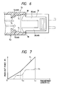
- the mutual contact resistance G between the male- and female-type terminals 45 and 46 increases greatly at and from an engagement length L M where a contact spring 46a disposed within the female-type terminal 46 begins to make contact with the male-type terminal 45.
- the connector removing mechanism 48 when a set of male and female connectors 32 and 33 are engaged with each other, the connector removing mechanism 48 generates the push-out force F which pushes the male and female connectors 32 and 33 away from each other. Because the push-out force F to be generated by the connector removing mechanism 48 is set larger than the mutual contact resistance caused by and between the male and female terminals 45 and 46 respectively stored within their associated connectors, when the two connectors are held in their mutually partially engaged condition, both of the male and female connectors are caused to move in their mutually removing directions at least until the mutually connected condition between the male and female terminals 45 and 46 is removed.
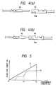
- a connector lock mechanism 51 according to the second embodiment in a connector lock mechanism 51 according to the second embodiment, the arm guide surfaces 40 and 41 employed in the connector lock mechanism 31 according to the first embodiment of the invention are improved, and the remaining portions of the connector lock mechanism 51 are similar in structure those of the first embodiment.
- the two flexible elastic pieces 68 are respectively formed in such a manner that they project from the two side surfaces of the flexible arm 62 located near to the leading end portion thereof.
- the two push-out guide surfaces 69 are respectively provided on the two side surfaces of the upper portion of the housing of the female connector 60 at the height position where their associated flexible elastic pieces 68 can be contacted with the push-out guide surfaces 69 when the flexible arm 62 is flexed downwardly by the arm guide surface 65.
- the two push-out guide surfaces 69 are respectively tapered surfaces which are capable of flexing a pair of flexible elastic pieces 68 and 68 as the mutual engagement between the male and female connectors advances.
- the push-out force F to be generated by the connector removing mechanism 70 has the same characteristic line as the characteristic line F1 shown in Fig. 5.
- the flexible elastic pieces 68 and push-out guide surfaces 69 forming the connector removing mechanism 70 are respectively formed integrally with their associated connector housings, when compared with the conventional connector removing mechanism using separate parts such as compression springs, the number of parts required in the connectors as well as the number of assembling steps thereof can be reduced, which makes it possible to reduce the manufacturing costs of the connectors.
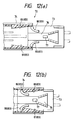
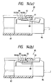
- the other connector namely, the female connector 74 includes an arm guide surface 78 capable of flexing the flexible arm 76 until the mutual engagement length between the male and female connectors reaches a preset length.
- the arm guide surface 78 includes securing means 79 which is formed integrally with the arm guide surface 78 and also which, when the connector mutual engagement length reaches the preset length, can secure the engaging portion 77 to thereby lock the connector mutually engaged condition.
- the arm guide surface 78 is formed in the inner upper surface of the housing of the female connector 74 in such a manner that the engaging portion 77 can be contacted with the arm guide surface 78 when the male and female connectors 73 and 74 are operated for their mutual engagement.
- the arm guide surface 78 is able to flex the flexible arm 76 as the mutual engagement between the male and female connectors advances.
- the engaging means 79 consists of a rectangular-shaped securing hole which is formed in the rear end portion of the arm guide surface 78 in such a manner that the engaging portion 77 can be engaged with the engaging means 79.
- the female connector 74 includes two male-type terminals which correspond the female-terminals stored within the male connector 73.
- the elasticity of the flexible elastic pieces 80 and the inclination angles of the push-out guide surfaces 81 are set in such a manner that the push-out force to be generated by the flexing of the flexible elastic pieces is larger than the mutual contact resistance caused by and between the male and female terminals.
- the flexible elastic pieces 80 respectively pass through their associated push-out guide surfaces 81 while in contact therewith and are then secured to the rear ends of their associated push-out guide surfaces 81.
- the push-out force of the present connector removing mechanism 83 provides the same characteristic line as the characteristic line F1 shown in Fig. 5.
- the connector removing mechanism 83 when a set of male and female connectors 73 and 74 are operated for their mutual engagement, the connector removing mechanism 83 generates the push-out force which pushes the male and female connectors in their mutually removing directions where the male and female connectors 73 and 74 are removed from each other. Since the push-out force to be generated by the connector removing mechanism 83 is set larger than the mutual contact resistance caused by and between the male- and female-type terminals respectively stored within their associated connectors, when the male and female connectors are partially engaged with each other, the male connector is pushed back in the removing direction at least until the mutually connected condition between the male- and female-type terminals is removed completely. This makes it possible to surely detect the half engagement between the male and female connectors 73 and 74 without overlooking it.
- the flexible elastic pieces 80 and push-out guide surfaces 81 forming the present connector removing mechanism 83 are respectively formed integrally with their associated connectors, when compared with the conventional connector removing mechanism which employs separate parts such as compression springs, the number of parts required in the connectors as well as the number of assembling steps thereof can be reduced, thereby being able to reduce the manufacturing costs thereof.
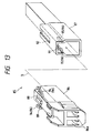
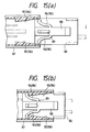
- a connector lock mechanism 85 relates to a set of male and female connectors 86 and 87.
- One of the two connectors, namely, the male connector 86 includes a single flexible arm 88 formed in such a manner as to extend along a direction thereof (in Fig. 13, in the direction of an arrow D) in which the male connector 86 can be engaged with the other connector, namely, the female connector 87, while the flexible arm 88 includes an engaging portion 89 'formed integrally therewith.
- the other connector namely, the female connector 87 includes an arm guide surface 91 with securing means 92 formed integrally therewith.
- the arm guide surface 91 is capable of flexing the flexible arm 88 until the mutual engagement length between the male and female connectors reaches a preset length.
- the securing means 92 of the arm guide surface 91 when the mutual engagement length reaches the present length, is capable of securing the engaging portion 89 of the flexible arm 88 to thereby lock the mutually engaged condition between the male and female connectors.
- the securing means 92 consists of a rectangular-shaped securing hole which is formed in front of the arm guide surface 91 in such a manner that the engaging portion 89 of the flexible arm 88 can be fitted into the securing means 92.
- the present female connector 87 stores and holds therein two male-type terminals which corresponds to the female-type terminals held within the male connector 86.
- the elasticity of the flexible elastic pieces 94 and the inclination angles of the push-out guide surfaces 95 are set in such a manner that the push-out force to be generated by the flexing of the flexible elastic pieces 94 is larger than the mutual contact resistance caused by and between male-type and female-type terminals which are respectively stored within the two connectors.
- the flexible elastic pieces 94 are returned back to their original conditions together with the flexible arm 88, which makes it possible to prevent the possible fatigue of the flexible pieces 94 caused by holding the flexible pieces 94 in the flexed condition for a long period of time.
- the push-out force to be generated by the connector removing mechanism 96 provides the same characteristic line as the characteristic line F1 shown in Fig. 5.
- the flexible elastic pieces 94 and push-out guide surfaces 95 forming the present connector removing mechanism 96 are respectively provided in their associated connectors in such a manner that they are formed integrally therewith. That is, when compared with the conventional connector removing mechanism which uses separate parts such as compression springs or the like, the present connector removing mechanism 96 can reduce the number of parts required in the connectors as well as the number of assembling steps thereof, which in turn makes it possible to reduce the manufacturing costs thereof.
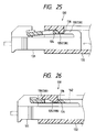
- the other connector namely, the female connector 100 comprises a pair of arm guide surfaces 104 respectively which are capable of flexing their associated flexible arm 102 until the mutual engagement length between the male and female connectors reaches a preset length.
- the arm guide surfaces 104 respectively include securing means 105 which, when the connector mutual engagement length reaches the preset length, can secure their associated engaging portions 103 to thereby lock the mutually engaged condition between the two connectors.
- the present securing means 105 respectively consist of stepped portions which are formed in the rear end portions of their associated arm guide surfaces 104 in such a manner that their associated engaging portions 103 can be engaged with the securing means 105.
- the connector removing mechanism 107 applies to the male and female connectors 99 and 100 the push-out force which pushes them in their mutually removing directions. Since the push-out force to be generated by the connector removing mechanism 107 is set larger than the mutual contact resistance between the male-type and female-type terminals which are respectively stored within the male and female connectors, when the male and female connectors are partially engaged with each other, the male and female connectors are pushed back in their mutually removing directions at least until the mutually connected condition of the male and female terminals is removed. Therefore, the present connector lock mechanism 98 is surely able to detect the partially engaged condition between the male and female connectors without fail.
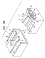
- the free end portions of the two flexible arms 119 which are situated in the rear end side of the male connector housing are connected together to thereby form an operation portion which can be used to remove the locking of the mutual engagement between the male and female connectors.
- the engaging portion 120 of the flexible arms 119 is formed in such a manner as to project from the outer surfaces of the flexible arms 119 toward the male connector housing side, while the upwardly projecting length thereof increases gradually from the front end side of the male connector housing toward the rear end side thereof.
- the present male connector 116 includes in the width or lateral direction thereof two terminal storage chambers 116a which are capable of storing female-type terminals therein.
- the other connector namely, the female connector 117 comprises an arm guide surface 121 which is capable of flexing the flexible arms 119 until the mutual engagement length between the male and female connectors reaches a preset length
- the arm guide surface 121 includes securing means 105 which, when the connector mutual engagement length reaches the preset length, is capable of securing the engaging portion 120 of the flexible arms 119 to thereby lock the mutually engaged condition between the male and female connectors.
- the arm guide surface 121 is formed on the side surface of the housing of the female connector 117 in such a manner that, when the male and female connectors 116 and 117 are operated for their mutual engagement, the engaging portion 120 of the flexible arms 119 contact the arm guide surface 121.
- the arm guide surface 121 is able to flex the flexible arms 119 gradually downwardly as the mutual engagement between the male and female connectors advances.
- the securing means 123 consists of a rectangular-shaped securing hole which is formed in the rear end portion of the arm guide surface 121 in such a manner that the engaging portion 120 can be engaged with the securing means 123.
- the female connector 117 stores and holds therein two male-type terminals which correspond to the female-type terminals stored within the male connector 116.
- the pair of flexible arms 119 including the engaging portion 120 between them and the pair of arm guide surface 121 function as a first connector removing mechanism 125, but also the pair of flexible arms 119 and a pair of push-out guide surfaces 126 and 126 respectively formed in the two inner surfaces of the female connector 117 function as a second connector removing mechanism 127.
- the flexible elastic pieces and push-out guide surfaces respectively cooperating in forming the present connector removing mechanisms are provided in two or more sets, for example, if the respective sets of flexible elastic pieces and push-out guide surfaces are shifted in the operation timings from one another, the push-out force to be generated by the present connector removing mechanisms can be made to vary. Also, if the two or more sets of flexible elastic pieces and push-out guide surfaces are operated simultaneously, then a large push-out force can be obtained easily and, therefore, even if the number of terminals to be stored within the respective connectors is large, the present connector removing mechanisms are surely able to provide a necessary and sufficient push-out force.
- the connector lock mechanism 130 not only the pair of flexible arms 119, 119 and the arm guide surface 135 function as a first connector removing mechanism 125, but also the pair of flexible arms 119, 119 and a pair of push-out guide surfaces 139, 139 respectively formed in the two inner surfaces of the female connector 132 function as a second connector removing mechanism 140.
- a connector lock mechanism which comprises a connector removing mechanism.
- the present connector removing mechanism is composed of a flexible elastic piece formed integrally with one connector, and a push-out guide surface which is formed integrally with the other connector and also which, when the two connectors are operated for their mutual engagement, can deform the flexible elastic piece elastically to thereby generate a push-out force that separates the two connectors from each other in their mutually removing directions.
- the flexible arm may also serve as the flexible elastic piece and the arm guide surface may also serve as the push-out guide surface. That is, in the present preferred embodiment, the respective connectors can be simplified in structure, which in turn can enhance the moldability of the connectors as well as the yield of the products.
Landscapes
- Details Of Connecting Devices For Male And Female Coupling (AREA)
Applications Claiming Priority (2)
| Application Number | Priority Date | Filing Date | Title |
|---|---|---|---|
| JP09622598A JP3467185B2 (ja) | 1998-04-08 | 1998-04-08 | コネクタのロック機構 |
| JP9622598 | 1998-04-08 |
Publications (2)
| Publication Number | Publication Date |
|---|---|
| EP0949717A2 true EP0949717A2 (de) | 1999-10-13 |
| EP0949717A3 EP0949717A3 (de) | 2000-09-13 |
Family
ID=14159300
Family Applications (1)
| Application Number | Title | Priority Date | Filing Date |
|---|---|---|---|
| EP99302483A Withdrawn EP0949717A3 (de) | 1998-04-08 | 1999-03-30 | Ein Verbinderveriegelungsmechanismus |
Country Status (3)
| Country | Link |
|---|---|
| US (2) | US6712636B2 (de) |
| EP (1) | EP0949717A3 (de) |
| JP (1) | JP3467185B2 (de) |
Cited By (8)
| Publication number | Priority date | Publication date | Assignee | Title |
|---|---|---|---|---|
| GB2356985A (en) * | 1999-12-01 | 2001-06-06 | Yazaki Corp | A connector arrangement with means to prevent incomplete coupling and a release mechanism |
| DE10013823C1 (de) * | 2000-03-21 | 2002-01-03 | Fci Automotive Deutschland Gmb | Elektrischer Steckverbinder |
| US6416345B1 (en) | 1999-08-30 | 2002-07-09 | Yazaki Corporation | Connector lock mechanism with elastic arm portion |
| US6592404B2 (en) | 2000-06-05 | 2003-07-15 | Yazaki Corporation | Half fit preventive connector |
| EP1282200A3 (de) * | 2001-07-31 | 2004-01-28 | Yazaki Corporation | Verriegelungseinrichtung für zwei Stücke |
| DE10028407B4 (de) * | 1999-06-16 | 2005-02-03 | Yazaki Corp. | Steckverbindung mit Verriegelungsmechanismus |
| GB2408853A (en) * | 2003-12-02 | 2005-06-08 | Cheng Uei Prec Ind Co Ltd | Electrical connector latching apparatus |
| EP1986286A3 (de) * | 2007-04-25 | 2008-11-05 | Sumitomo Wiring Systems, Ltd. | Steckverbinder |
Families Citing this family (34)
| Publication number | Priority date | Publication date | Assignee | Title |
|---|---|---|---|---|
| USD242736S (en) * | 1976-01-20 | 1976-12-14 | Thermal Hydraulics Corporation | Plant pot |
| JP4549165B2 (ja) * | 2004-11-19 | 2010-09-22 | モレックス インコーポレイテド | 電気コネクタ装置 |
| US20070093114A1 (en) * | 2005-10-26 | 2007-04-26 | Yi-Yu Chang | Resilient latching device |
| JP4863823B2 (ja) * | 2006-09-12 | 2012-01-25 | 矢崎総業株式会社 | コネクタのロック構造 |
| US8109883B2 (en) | 2006-09-28 | 2012-02-07 | Tyco Healthcare Group Lp | Cable monitoring apparatus |
| US8668651B2 (en) | 2006-12-05 | 2014-03-11 | Covidien Lp | ECG lead set and ECG adapter system |
| US7402068B1 (en) * | 2007-05-14 | 2008-07-22 | Gm Global Technology Operations, Inc. | High voltage interlock connection |
| US7396250B1 (en) * | 2007-07-13 | 2008-07-08 | Kui-Hsien Huang | Plugging device for network cable |
| CA2646037C (en) | 2007-12-11 | 2017-11-28 | Tyco Healthcare Group Lp | Ecg electrode connector |
| USD737979S1 (en) | 2008-12-09 | 2015-09-01 | Covidien Lp | ECG electrode connector |
| JP4784673B2 (ja) * | 2009-03-24 | 2011-10-05 | パナソニック電工株式会社 | コネクタ |
| US8694080B2 (en) | 2009-10-21 | 2014-04-08 | Covidien Lp | ECG lead system |
| CA2746944C (en) | 2010-07-29 | 2018-09-25 | Tyco Healthcare Group Lp | Ecg adapter system and method |
| JP5569267B2 (ja) * | 2010-09-03 | 2014-08-13 | 住友電装株式会社 | コネクタ |
| ES2762190T3 (es) | 2011-07-22 | 2020-05-22 | Kpr Us Llc | Conector de electrodo ECG |
| US8634901B2 (en) | 2011-09-30 | 2014-01-21 | Covidien Lp | ECG leadwire system with noise suppression and related methods |
| CN103811941A (zh) * | 2012-11-15 | 2014-05-21 | 鸿富锦精密工业(深圳)有限公司 | 排线固定装置 |
| USD771818S1 (en) | 2013-03-15 | 2016-11-15 | Covidien Lp | ECG electrode connector |
| DK2967396T3 (da) | 2013-03-15 | 2019-05-20 | Kpr Us Llc | Elektrodekonnektor med et ledende element |
| US9408546B2 (en) | 2013-03-15 | 2016-08-09 | Covidien Lp | Radiolucent ECG electrode system |
| US20150214663A1 (en) * | 2014-01-29 | 2015-07-30 | Hyundai Motor Company | Connector assembly for vehicle |
| TW201601394A (zh) * | 2014-06-26 | 2016-01-01 | 道格拉斯 J 伍斯特曼 | 電源插座組件 |
| WO2016032011A1 (en) * | 2014-08-25 | 2016-03-03 | Lg Electronics Inc. | Wireless headset and method of contrlling the same |
| DE102016100382B3 (de) * | 2016-01-12 | 2017-02-23 | HARTING Electronics GmbH | Steckverbinder |
| JP6569131B2 (ja) * | 2016-04-26 | 2019-09-04 | 株式会社オートネットワーク技術研究所 | 嵌合検知機能を有する電気接続装置 |
| DE102016219975A1 (de) * | 2016-10-13 | 2018-04-19 | BSH Hausgeräte GmbH | Hausgerät mit einer Steckverbindung zu einem Netzkabel |
| KR101872837B1 (ko) * | 2016-11-25 | 2018-06-29 | 주식회사 유라코퍼레이션 | 체결확인부를 구비한 커넥터 |
| KR101872839B1 (ko) * | 2016-11-25 | 2018-06-29 | 주식회사 유라코퍼레이션 | 체결확인부를 구비한 커넥터 |
| USD884638S1 (en) * | 2018-06-08 | 2020-05-19 | J.S.T. Corporation | Electrical connector |
| CN111435772B (zh) * | 2019-01-15 | 2025-01-03 | 安普泰科电子韩国有限公司 | 连接器组件和包括连接器组件的家用电器 |
| KR102826779B1 (ko) * | 2019-01-15 | 2025-07-02 | 타이코에이엠피 주식회사 | 커넥터 어셈블리 및 이를 구비하는 전자기기 |
| JP6712376B1 (ja) * | 2019-07-22 | 2020-06-24 | Smk株式会社 | フローティング機構付き同軸コネクタ |
| JP7533365B2 (ja) * | 2021-06-02 | 2024-08-14 | 株式会社オートネットワーク技術研究所 | コネクタ |
| KR20240057694A (ko) * | 2022-10-25 | 2024-05-03 | 몰렉스 엘엘씨 | 전기 커넥터 및 이를 포함하는 전기 커넥터 조립체 |
Family Cites Families (24)
| Publication number | Priority date | Publication date | Assignee | Title |
|---|---|---|---|---|
| DE2950557C2 (de) * | 1979-12-15 | 1983-01-13 | Kabelwerke Reinshagen Gmbh, 5600 Wuppertal | Elektrische Kabelsteckvorrichtung |
| NZ196720A (en) * | 1980-05-02 | 1985-04-30 | Amp Inc | Two part electrical connector with co-operating latches |
| US4431244A (en) * | 1980-08-11 | 1984-02-14 | Anhalt John W | Electrical connector with integral latch |
| FR2576155B1 (fr) * | 1985-01-14 | 1987-07-31 | Labinal | Perfectionnements au verrouillage de deux elements d'un boitier de connexions electriques |
| DE3826389A1 (de) | 1987-09-09 | 1989-03-30 | Boehringer Mannheim Gmbh | Typ ii-restriktionsendonuklease ksp632i |
| JP2522319Y2 (ja) * | 1991-03-13 | 1997-01-16 | 矢崎総業株式会社 | コネクタ |
| US5788527A (en) * | 1991-04-04 | 1998-08-04 | Magnetek, Inc. | Electrical connector with improved safety latching for a fluorescent-lighting ballast |
| JP2682554B2 (ja) * | 1992-05-08 | 1997-11-26 | 矢崎総業株式会社 | コネクタのロック機構 |
| JPH0650268U (ja) * | 1992-12-07 | 1994-07-08 | 住友電装株式会社 | コネクタ |
| JP2597289Y2 (ja) * | 1993-11-08 | 1999-07-05 | 矢崎総業株式会社 | ロック機構を備えたコネクタハウジング |
| JP2907373B2 (ja) * | 1994-05-10 | 1999-06-21 | 矢崎総業株式会社 | コネクタのロック結合検知構造 |
| US5486117A (en) * | 1994-08-09 | 1996-01-23 | Molex Incorporated | Locking system for an electrical connector assembly |
| US5769650A (en) * | 1995-06-19 | 1998-06-23 | Sumitomo Wiring Systems, Ltd. | Connector and cover therefor |
| EP0757411A3 (de) * | 1995-08-03 | 1997-10-15 | Sumitomo Wiring Systems | Verbinder |
| JPH09139251A (ja) * | 1995-11-14 | 1997-05-27 | Sumitomo Wiring Syst Ltd | コネクタ |
| JP3705452B2 (ja) | 1995-12-28 | 2005-10-12 | 矢崎総業株式会社 | 半嵌合防止コネクタ |
| JP3301522B2 (ja) * | 1996-04-26 | 2002-07-15 | 住友電装株式会社 | コネクタ |
| DE29724486U1 (de) * | 1996-04-30 | 2001-08-30 | Framatome Connectors International, Courbevoie | Steckverbinder mit Sekundärverriegelung |
| US6068507A (en) * | 1996-11-04 | 2000-05-30 | Molex Incorporated | Housing adapted to an electrical connector position assurance system |
| US5775930A (en) * | 1996-12-13 | 1998-07-07 | General Motors Corporation | Electrical connector with locking connector position assurance member |
| DE19723029B4 (de) * | 1997-06-03 | 2004-11-04 | Holzer, Walter, Prof. Dr.h.c. Ing. | Anordnung zur Rastung von elektrischen Steckverbindungen für Lampen |
| US5910027A (en) * | 1997-10-08 | 1999-06-08 | Ut Automotive Dearborn, Inc. | Connector position assurance |
| JP3415008B2 (ja) * | 1997-11-12 | 2003-06-09 | 住友電装株式会社 | コネクタ |
| DE19828636C2 (de) * | 1998-06-26 | 2000-07-06 | Framatome Connectors Int | Steckverbinder mit Schnappverschluß |
-
1998
- 1998-04-08 JP JP09622598A patent/JP3467185B2/ja not_active Expired - Fee Related
-
1999
- 1999-03-30 EP EP99302483A patent/EP0949717A3/de not_active Withdrawn
- 1999-04-02 US US09/283,998 patent/US6712636B2/en not_active Expired - Fee Related
-
2004
- 2004-02-06 US US10/772,469 patent/US7025618B2/en not_active Expired - Fee Related
Cited By (11)
| Publication number | Priority date | Publication date | Assignee | Title |
|---|---|---|---|---|
| DE10028407B4 (de) * | 1999-06-16 | 2005-02-03 | Yazaki Corp. | Steckverbindung mit Verriegelungsmechanismus |
| US6416345B1 (en) | 1999-08-30 | 2002-07-09 | Yazaki Corporation | Connector lock mechanism with elastic arm portion |
| GB2356985A (en) * | 1999-12-01 | 2001-06-06 | Yazaki Corp | A connector arrangement with means to prevent incomplete coupling and a release mechanism |
| GB2356985B (en) * | 1999-12-01 | 2002-02-06 | Yazaki Corp | Half-fitting prevention connector |
| US6488524B2 (en) | 1999-12-01 | 2002-12-03 | Yazaki Corporation | Half-fitting prevention connector |
| DE10013823C1 (de) * | 2000-03-21 | 2002-01-03 | Fci Automotive Deutschland Gmb | Elektrischer Steckverbinder |
| US6592404B2 (en) | 2000-06-05 | 2003-07-15 | Yazaki Corporation | Half fit preventive connector |
| DE10126957B4 (de) * | 2000-06-05 | 2006-06-01 | Yazaki Corp. | Steckverbindung mit Mitteln zur Verhinderung eines unvollständig verbundenen Zustands |
| EP1282200A3 (de) * | 2001-07-31 | 2004-01-28 | Yazaki Corporation | Verriegelungseinrichtung für zwei Stücke |
| GB2408853A (en) * | 2003-12-02 | 2005-06-08 | Cheng Uei Prec Ind Co Ltd | Electrical connector latching apparatus |
| EP1986286A3 (de) * | 2007-04-25 | 2008-11-05 | Sumitomo Wiring Systems, Ltd. | Steckverbinder |
Also Published As
| Publication number | Publication date |
|---|---|
| US6712636B2 (en) | 2004-03-30 |
| JP3467185B2 (ja) | 2003-11-17 |
| EP0949717A3 (de) | 2000-09-13 |
| US7025618B2 (en) | 2006-04-11 |
| US20040156675A1 (en) | 2004-08-12 |
| US20020022394A1 (en) | 2002-02-21 |
| JPH11297423A (ja) | 1999-10-29 |
Similar Documents
| Publication | Publication Date | Title |
|---|---|---|
| US7025618B2 (en) | Connector lock mechanism | |
| US6332800B2 (en) | Connector assembly having inertia locking mechanism | |
| US6592404B2 (en) | Half fit preventive connector | |
| US6712635B1 (en) | Connector | |
| US6241542B1 (en) | Connector with shorting terminal | |
| EP0389955B1 (de) | Doppelt verriegelnder Verbinder für einen elektrischen Endkontakt | |
| US5647754A (en) | Short-circuit connector | |
| US6533600B1 (en) | Connector fitting construction | |
| CN114079202B (zh) | 连接器 | |
| CN103238255B (zh) | 连接器组件 | |
| US7114997B2 (en) | Electrical connector | |
| CN109616829B (zh) | 连接器 | |
| US20080233789A1 (en) | Lock structure of connector | |
| US5088938A (en) | Terminal locking block for electrical connectors | |
| JPH10144400A (ja) | コネクタ | |
| US20020025711A1 (en) | Connector fitting structure | |
| US7223113B2 (en) | Connector and a connector assembly | |
| JP3741351B2 (ja) | 半嵌合防止コネクタ | |
| JP3311228B2 (ja) | 端子係止具付きコネクタ | |
| JP3437102B2 (ja) | 半嵌合防止コネクタ | |
| US5066253A (en) | Electric connector with a terminal locking mechanism | |
| US6422894B1 (en) | Connector fitting detection construction | |
| JPH11111390A (ja) | 嵌合検知コネクタ | |
| CN111834788A (zh) | 带有端子锁的电端子壳体 | |
| US6659785B2 (en) | Connector |
Legal Events
| Date | Code | Title | Description |
|---|---|---|---|
| PUAI | Public reference made under article 153(3) epc to a published international application that has entered the european phase |
Free format text: ORIGINAL CODE: 0009012 |
|
| AK | Designated contracting states |
Kind code of ref document: A2 Designated state(s): DE FR GB |
|
| AX | Request for extension of the european patent |
Free format text: AL;LT;LV;MK;RO;SI |
|
| PUAL | Search report despatched |
Free format text: ORIGINAL CODE: 0009013 |
|
| AK | Designated contracting states |
Kind code of ref document: A3 Designated state(s): AT BE CH CY DE DK ES FI FR GB GR IE IT LI LU MC NL PT SE |
|
| AX | Request for extension of the european patent |
Free format text: AL;LT;LV;MK;RO;SI |
|
| 17P | Request for examination filed |
Effective date: 20001227 |
|
| AKX | Designation fees paid |
Free format text: DE FR GB |
|
| 17Q | First examination report despatched |
Effective date: 20010919 |
|
| GRAP | Despatch of communication of intention to grant a patent |
Free format text: ORIGINAL CODE: EPIDOSNIGR1 |
|
| RIN1 | Information on inventor provided before grant (corrected) |
Inventor name: FUKUDA, MASARU |
|
| STAA | Information on the status of an ep patent application or granted ep patent |
Free format text: STATUS: THE APPLICATION IS DEEMED TO BE WITHDRAWN |
|
| RAP1 | Party data changed (applicant data changed or rights of an application transferred) |
Owner name: YAZAKI CORPORATION |
|
| 18D | Application deemed to be withdrawn |
Effective date: 20061229 |