EP0949769A1 - CDMA Empfangsvorrichtung und Kommunikationssystem mit adaptiver Antenne - Google Patents
CDMA Empfangsvorrichtung und Kommunikationssystem mit adaptiver Antenne Download PDFInfo
- Publication number
- EP0949769A1 EP0949769A1 EP19990106814 EP99106814A EP0949769A1 EP 0949769 A1 EP0949769 A1 EP 0949769A1 EP 19990106814 EP19990106814 EP 19990106814 EP 99106814 A EP99106814 A EP 99106814A EP 0949769 A1 EP0949769 A1 EP 0949769A1
- Authority
- EP
- European Patent Office
- Prior art keywords
- plural
- adaptive
- incoming
- desired signal
- receiving
- Prior art date
- Legal status (The legal status is an assumption and is not a legal conclusion. Google has not performed a legal analysis and makes no representation as to the accuracy of the status listed.)
- Granted
Links
Images


Classifications
-
- H—ELECTRICITY
- H04—ELECTRIC COMMUNICATION TECHNIQUE
- H04B—TRANSMISSION
- H04B7/00—Radio transmission systems, i.e. using radiation field
- H04B7/02—Diversity systems; Multi-antenna system, i.e. transmission or reception using multiple antennas
- H04B7/04—Diversity systems; Multi-antenna system, i.e. transmission or reception using multiple antennas using two or more spaced independent antennas
- H04B7/08—Diversity systems; Multi-antenna system, i.e. transmission or reception using multiple antennas using two or more spaced independent antennas at the receiving station
- H04B7/0891—Space-time diversity
- H04B7/0897—Space-time diversity using beamforming per multi-path, e.g. to cope with different directions of arrival [DOA] at different multi-paths
-
- H—ELECTRICITY
- H04—ELECTRIC COMMUNICATION TECHNIQUE
- H04B—TRANSMISSION
- H04B7/00—Radio transmission systems, i.e. using radiation field
- H04B7/02—Diversity systems; Multi-antenna system, i.e. transmission or reception using multiple antennas
- H04B7/04—Diversity systems; Multi-antenna system, i.e. transmission or reception using multiple antennas using two or more spaced independent antennas
- H04B7/08—Diversity systems; Multi-antenna system, i.e. transmission or reception using multiple antennas using two or more spaced independent antennas at the receiving station
- H04B7/0837—Diversity systems; Multi-antenna system, i.e. transmission or reception using multiple antennas using two or more spaced independent antennas at the receiving station using pre-detection combining
- H04B7/0842—Weighted combining
- H04B7/086—Weighted combining using weights depending on external parameters, e.g. direction of arrival [DOA], predetermined weights or beamforming
-
- H—ELECTRICITY
- H04—ELECTRIC COMMUNICATION TECHNIQUE
- H04B—TRANSMISSION
- H04B7/00—Radio transmission systems, i.e. using radiation field
- H04B7/02—Diversity systems; Multi-antenna system, i.e. transmission or reception using multiple antennas
- H04B7/04—Diversity systems; Multi-antenna system, i.e. transmission or reception using multiple antennas using two or more spaced independent antennas
- H04B7/0408—Diversity systems; Multi-antenna system, i.e. transmission or reception using multiple antennas using two or more spaced independent antennas using two or more beams, i.e. beam diversity
Definitions
- the present invention relates to a CDMA (Code Division Multiple Access) adaptive antenna receiving apparatus and more particularly, to a CDMA adaptive antenna receiving apparatus for separating and synthesizing a plural of desired signal components incoming at a plural of different timings and from a plural of different directions at each timing.
- CDMA Code Division Multiple Access
- the CDMA system capable of developing greatly a capacity for subscribers has been remarkable as a multiple access system for use in a mobile communication system including a base station and portable mobile stations.
- the CDMA adaptive antenna receiving apparatus for use in a CDMA mobile communication system is subjected to eliminate the interference by means of the directivity of the antenna. This is explained in “TDL Adaptive Array Antenna Employing Spread Process Gain for Spectrum Spread Multi-dimensional Connection”, Oho, Kohno and Imai, Electronics Information and Communication Society Journal, vol. J75-BII, No. 11, pp. 815-825, 1992. This is also explained in “Characteristic of Decision Feedback type Coherent Adaptive Diversity in DS-CDMA", Tanaka, Miki and Sawahashi, Electronics Information and Communication Society, Radio Communication System Study Group Technical Report, RCS96-102, November 1996.
- Fig. 5 is a block diagram showing an example of the conventional CDMA adaptive antenna receiving apparatus, so-called RAKE receiver. Defining N (N is an integer of 2 or more) for the number of receiving antennas and M (M is an integer of 2 or more) for the number of multi-paths, a CDMA adaptive antenna receiving apparatus for No. k user (k is an integer of 1 or more) will be explained. Signals received at antennas 110-1 to 110-N are classified into a first through No. M paths in accordance with delay times thereof, and are introduced into delay circuits 120-2 to 120-M and adaptive receivers 130-1 to 130-M. Delay circuits 120-2 to 120-M may delay the input signals so as to synchronize with the first path.
- Delay circuit 120-1 having a time delay of 0 is omitted from the drawing. Outputs of the adaptive receivers are summed at adder 140 and the output therefrom is fed into decision device 150. The output signal from decision device 150 is not only output as a reception symbol of the No. k user but also sent to adaptive receivers 130-1 to 130-M.
- Adaptive receivers 130-1 to 130-M have the same construction.
- Fig. 6 shows the adaptive receiver for No. m path (1 ⁇ m ⁇ M).
- Received signals are despread by despread devices 161-1 to 161-N, and are thereafter sent to multipliers 162-1 to 162-N and delay circuit 163.
- the received signals are multiplied by reception weights at multipliers 161-1 to 161-N and then are summed for weight synthesizing at adder 164.
- the reception weights are components of a vector. Each component of the vector is employed at multipliers 161-1 to 161-N.
- the weight-synthesized signal is sent to multiplier 165, communication channel estimating device 166 and subtracter 169.
- Communication channel estimating device 166 may estimate a communication distortion based on the output from 164.
- Complex conjugate generator 167 generates a complex conjugate number of the communication distortion that is multiplied by the output of adder 164 at multiplier 165.
- the output from multiplier 165 is a demodulated signal to be sent to adder 140 shown in Fig. 5.
- the outputs from adaptive receivers 130-1 to 130-M are added with each other at adder 140 for performing the RAKE synthesis, and then a data symbol is decided at decision device 150.
- adaptive receiver 130-m (1 ⁇ m ⁇ M)
- the output from decision device 150 is multiplied by the communication channel distortion output from communication channel estimating device 166 to be input into subtracter 169.
- Subtracter 169 computes an error by subtracting the output of adder 164 from the output of multiplier 168.
- the error is fed to adaptive update device 170.
- Adaptive update device 170 updates the reception weight vector by using the error from subtracter 170 and the signals that are received at the antennas and delayed by a demodulation time at delay circuit 163.
- a known algorithm for example, Least Mean Square Algorithm
- the conventional technology has an disadvantage in which the plural desired signals incoming from different directions at the same time can not be separated and synthesized. This is because only one reception weight vector is provided per adaptive receiver.
- Another disadvantage of the conventional technology is that the convergence speed of the reception weight vector is slow and the response is low. This is because the process for deciding the initial value of the reception weight vector is identical for any communication channel, and the previous reception weight vector before interruption is not employed at the beginning of next update operation.
- An object of the present invention is to provide a CDMA adaptive antenna receiving apparatus capable of separating and synthesizing the plural desired signals incoming from different directions at the same time.
- Another object of the present invention is to provide a CDMA adaptive antenna receiving apparatus having an advantageous convergence speed of a reception weight vector and response.
- the CDMA adaptive antenna receiving apparatus comprises a plural of adaptive receiving units in each adaptive receiver. This constitution enables to provide a directivity for each of desired signals incoming at different timings and from different directions at the same time, and thus the first object may be achieved.
- the present invention further comprises a means for controlling the reception weight vectors. This constitution enables to anticipate the incoming directions of the desired signals, and thus the second object may be achieved.
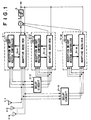
- N is an integer of 2 or more for the number of receiving antennas
- M is an integer of 2 or more
- L is an integer of 1 or more for the number of adaptive receiving unit
- a CDMA adaptive antenna receiving apparatus for No. k user k is an integer of 1 or more
- Signals received at different directional antennas 1-1 to 1-N are introduced into delay circuits 2-2 to 2-M.
- a directivity in a direction, for example, at every equal angle (360/N degrees) is assigned to each of antennas 1-1 to 1-N, respectively.
- Delay circuit 2-1 has a time delay of 0 and thus is omitted in the drawings.
- Delay circuits 2-2 to 2-M adaptively delay the received signals so that receivers 3-1 to 3-M may receive simultaneously the desired signal components incoming at different timings. As the result, the signals incoming at different timings may be supplied to each of receivers 3-1 to 3-M.
- the outputs from receivers 3-1 to 3-M are synthesized at adder 4.
- Decision device 5 may decide a transmission symbol of No. k user based on the output of adder 4. The decided symbol is fed back to receivers 3-1 to 3-M for use in the adaptive update of the reception weight vectors.
- Receivers 3-1 to 3-M comprise adaptive receivers 31-1 to 31-M and reception weight vector controllers 31-1 to 32-M, respectively.
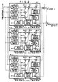
- Adaptive receivers 31-1 to 31-M have the same configuration, so adaptive receiver 31-1 will be explained first with reference to Fig. 2.
- Reception weight vector controller 32-1 may find desired signals incoming from L directions.
- Adaptive receiver 31-1 includes adaptive receiving units 6-1 to 6-L for the L directions as shown in Fig. 2.
- Other adaptive receivers 32-2 to 32-M may also find the number of desired signals by means of reception weight vector controllers 32-2 to 32-M,respectively, and thus may include the same number of adaptive units as well.
- adaptive receiving unit 6-1 As adaptive receiving units 6-1 to 6-L have the same configuration, adaptive receiving unit 6-1 is explained.
- the signal input to adaptive receiving unit 6-1 is despread by despread devices 61-1-1 to 61-1-N.
- Adaptive receiving unit 6-1 accepts at adaptive update device 69-1 thereof a selected reception weight vector 6-1-a from reception weight vector controller 32-1.
- Despread signals are multiplied by components of adaptive reception weight vector at multipliers 62-1-1 to 62-1-N, respectively, and then summed each other at adder 63-1.
- Each component of the adaptive reception weight vector is supplied to one of multipliers 62-1-1 to 62-1-N.
- the summed signal consists of signals which are received at antennas 1-1 to 1-N and weighted, and thus has a specific directivity.
- an antenna beam may be formed at the output of adder 63-1.
- the despread signals are also fed to delay circuit 64-1.
- Communication channel estimating device 67-1 accepts the weight-summed signal and estimates a communication channel distortion that is represented by a complex number.
- Complex conjugate generator 66-1 generates a complex conjugate number of the communication channel distortion.
- the weight-summed signal is multiplied by the complex conjugate number to be detected.
- Communication channel estimating device 67-1 may employ such an estimating process in which a transmission path characteristic (fading characteristic) is measured on a known symbol that is inserted periodically, and another transmission path characteristic of a signal symbol part other than the measured part is interporated. This process is described in "Fading Distortion Compensating Process for Ground Mobile Communication 16QAM", Sanpei, Electronics Information and Communication Society Journal, vol. J75-BII, No. 1, pp. 7-15, 1989.
- An adder 7 sums the demodulation results obtained at adaptive receiving units 6-1 to 6-N.
- the summed signal is a synthesis of the demodulation results of the desired signals incoming from different directions simultaneously.
- Subtracter 8 obtains an error that is a difference between the decided result obtained at decision device 5 and the output from adder 7. The error is employed as a symbol decision error of adaptive receiver 31-1 for adaptive receiving units 6-1 to 6-L in adaptive receiver 31-1 in common.
- adaptive receiving unit 6-1 A further explanation will be made with respect mainly to adaptive receiving unit 6-1.
- the common symbol decision error is multiplied by the output of communication channel estimating device 67-1 and then fed to adaptive update device 69-1.
- Adaptive update device 69-1 updates the selected reception weight vector obtained from reception weight vector controller 32-1 and sends the adaptive-updated adaptive reception weight vector to multipliers 62-1-1 to 62-1-N and reception weight vector controller 32-1.
- the despread signals from despread devices 61-1-1 to 61-1-N are delayed by a time period required to compute an error to be output from a multiplier 68-1, and then fed to adaptive update device 69-1.
- Adaptive update device 69-1 updates the reception weight vector by using these two signals; the error out of multiplier 68-1 and the despread signals output from delay circuit 64-1.
- the least mean square error control may be employed as the adaptive update algorithm.
- Reception weight vectors are updated independently to each other in adaptive receiving units 6-2 to 6-L as well by using the common symbol decision error output from subtracter 8.
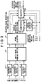
- Reception weight vector controllers 32-1 to 32-M have the same configuration, so reception weight vector controller 32-1 will be explained next with reference to Fig. 3.
- the signals received at antennas 1-1 to 1-N and fed to reception weight vector controller 32-1 are despread individually at despread devices 91-1 to 91-N, respectively.
- the despread signals are introduced into a multi-beam forming device 92.
- Multi-beam forming device 92 previously has a plural set of reception weight vectors for forming directional beams in different directions, and provides a plural of output beams and incoming directions corresponding thereto to beam selector 93.
- Directions of beams in multi-beam forming device 92 may be arranged equidistantly so that an output from any direction can be obtained.
- Beam selector 93 compares the incoming desired signal levels with each other and selects one or more (and L or less) outputs having relatively higher levels.
- the number of the reception weight vectors in multi-beam forming device 92 is generally prepared to be larger than that of outputs with relatively higher levels to be selected.
- Beam selector 93 feeds reception weight vectors for forming each of selected beams to a selector 94 and beam incoming directions thereof to comparator 95.
- Selector 94 accepts the selected beam reception weight vector from beam selector 93 and adaptive reception weight vectors 6-1-b to 6-L-b that are computed at adaptive update devices 69-1 to 69-L of adaptive receiving units 6-1 to 6-L, respectively, in adaptive receiver 31-1.
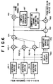
- Incoming direction estimating device 96 accepts adaptive reception weight vectors 6-1-b to 6-L-b from adaptive update devices 69-1 to 69-L of adaptive receiving units 6-1 to 6-L, respectively, in adaptive receiver 31-1 and estimates incoming directions thereof. Incoming direction estimating device 96 will be explained in detail with reference to Fig. 4.
- Incoming direction generator 96-1 generates incoming directions.
- Reception weight vector generator 96-2 converts the incoming directions into reception weight vector.
- a correlation computer 96-3 computes a correlation between the reception weight vector obtained from reception weight generator 96-2 and one of adaptive reception weight vectors 6-1-b to 6-L-b.
- a maximum value detector 96-4 obtains a maximum correlation value based on the result of the correlation computing with respect to a plural of incoming directions.
- Incoming direction output device 96-5 selects an incoming direction corresponding to the maximum correlation value among the incoming directions that are fed from incoming direction generating device 96-1, and feeds it to comparator 95.
- Incoming direction estimating device 96 consists of L groups of circuits in Fig. 4 but may also be realized with only one group of circuits capable of operating in a time-divisional processing.
- Comparator 95 compares the selected beam incoming directions supplied from beam selector 93 with the incoming directions corresponding to the adaptive reception weight vectors supplied from incoming direction estimating device 96, and sends information for selecting any one of the two kinds of incoming directions to selector94.
- Selector 94 selects the selected beam weight vector or the adaptive reception weight vector, and sends the selected one to each of adaptive update devices 69-1 to 69-L of adaptive receiving units 6-1 to 6-L in adaptive receiver 31-1 as each of selected reception weight vectors 6-1-a to 6-L-a.
- Selector 94 may also output specific values sustained therein, as described later, as selected reception weight vectors 6-1-a to 6-L-a.
- Comparator 95 operates to repeat a cycle consisting of L times of identical processes corresponding to L incoming directions, and serves to provide an initial value of the reception weight vector.
- Comparator 95 provides selector 94 with information for indicating which one of selected beam reception weight vector and adaptive reception weight vector should be selected at the time of initialization.
- the information may be determined as follows:
- the incoming direction of the selected beam and the incoming direction corresponding to the adaptive reception weight vector are compared. Then, in the case where an adaptive reception weight vector corresponding to the incoming direction of the selected beam is not present, an adaptive receiving unit having the reception weight vector corresponding to the beam newly selected for the selected direction as an initial value is added. To the contrary, in the case where no selected beam is present in the incoming direction corresponding to adaptive reception weight vector output from a certain adaptive receiving unit, an operation of the concerned adaptive receiving unit is halted.
- the addition of the adaptive receiving unit is realized by re-starting the operation of a halted adaptive receiving unit while providing the reception weight vector corresponding to the newly selected beam to the unit as an initial value of the selected reception weight vector. The addition and halt may be performed by providing a specific selected reception weight vector contained in selector 94 to the unit, or by varying the signal value on the control line not shown in the figures, for example.
- an operation of an adaptive receiving unit which has the adaptive reception weight vector for generating the most accurate output is to be continued, while operations of other adaptive receiving units having other adaptive reception weight vectors are to be halted.
- the signal levels output from adders 63-1 to 63-L within adaptive receiving units 6-1 to 6-L may be referred to so as to detect the adaptive receiving unit having the adaptive reception weight vector for generating the most accurate output.
- adaptive reception weight vectors are not determined.
- incoming directions may not be estimated because no adaptive reception weight vector is fed into incoming direction estimating device 96.
- no adaptive reception weight vector is fed into selector 94. Therefore, the selected beam weight vectors corresponding to incoming directions obtained by beam selector 93 are selected at selector 94 and sent to adaptive update devices 69-1 to 69-L of adaptive receiving units 6-1 to 6-L, respectively, in adaptive receiver 31-1.
- Reception weight vector controller 31-1 provides adaptive update devices 69-1 to 69-L with selected beam reception weight vectors that are reception weight vectors close to the optimum values as initial values for improving the convergence of the adaptive update of reception weight vectors to optimum values.
- incoming direction estimating device 96 estimates incoming directions by using the adaptive reception weight vectors of at the time of the termination of the previous communication as the inputs thereof, and feeds the incoming directions to comparator 95.
- Selector 94 selects either the selected beam weight vector or the adaptive reception weight vector based on the output of comparator 95.
- Selector 94 further sends it to adaptive update devices 69-1 to 69-L of adaptive receiving units 6-1 to 6-L, respectively, in adaptive receiver 31-1. This operation may allow the reception weight vectors to respond to the communication channel variation with ease.
- multi-beam forming device 92 serves as the same as that in the first embodiment, and beam selecting device 93 selects one beam having a relatively higher reception level.
- Comparator 95 compares the selected beam incoming direction with the incoming direction estimated on the basis of adaptive reception weight 6-1-b. comparator 95 instructs selector 94 to select adaptive reception weight 6-1-b in case of both directions being substantially coincident but to select the beam reception weight in the other cases.
- the present invention has no limitation regarding the arranging interval of the receiving antennas, though the directivities of the receiving antennas are exemplified as being equidistant in the above-described embodiments. For example, an arranging interval equal to a half wave-length of the carrier may also be employed.
- the present invention has no limitation regarding the number of receiving antennas.
- the present invention has also no limitation regarding the arrangement of the receiving antennas. For example, a circular arrangement and a linear arrangement may also be employed.
- the present invention has no limitation regarding the directivity of each receiving antenna. For example, an omni-antenna and a sector-antenna may also be used as each receiving antenna.
- the present invention may achieve the separating and synthesizing the plural desired signals incoming from different directions at the same time. This is because that the plural antenna beams can be prepared simultaneously.
- the adaptive reception weight vectors may converge on the optimum value rapidly. This is performed by the reception weight vector controller for obtaining the initial values close to the optimum values of the selected reception weight vectors and the adaptive receivers for updating the reception weight vectors to the optimum values based on the initial values.
- updating the reception weight vectors adaptively in a good response to the communication channel variation may be achieved. This is performed by initializing the operation of the selective receivers in accordance with the new incoming direction of the desired signal component on basis of the incoming direction estimated from the selected beam incoming direction and the adaptive reception weight vectors.
- updating the reception weight vectors adaptively in a good response to the communication channel variation may be achieved even in the case of a temporary disconnection of communication. This is because the adaptive reception weight vectors at the time before the disconnection may be employed after the disconnection.
- the power consumption may be lowered because the adaptive receiving units having the same reception weight vector do not operate. And because the operations of the adaptive receiving units for forming the directivities for the directions which have no selected beam incoming direction may be halted.
Landscapes
- Engineering & Computer Science (AREA)
- Computer Networks & Wireless Communication (AREA)
- Signal Processing (AREA)
- Radio Transmission System (AREA)
- Variable-Direction Aerials And Aerial Arrays (AREA)
- Mobile Radio Communication Systems (AREA)
- Noise Elimination (AREA)
Applications Claiming Priority (2)
| Application Number | Priority Date | Filing Date | Title |
|---|---|---|---|
| JP9462698 | 1998-04-07 | ||
| JP09462698A JP3465739B2 (ja) | 1998-04-07 | 1998-04-07 | Cdma適応アンテナ受信装置及び通信システム |
Publications (2)
| Publication Number | Publication Date |
|---|---|
| EP0949769A1 true EP0949769A1 (de) | 1999-10-13 |
| EP0949769B1 EP0949769B1 (de) | 2004-12-29 |
Family
ID=14115480
Family Applications (1)
| Application Number | Title | Priority Date | Filing Date |
|---|---|---|---|
| EP19990106814 Expired - Lifetime EP0949769B1 (de) | 1998-04-07 | 1999-04-06 | CDMA Empfangsvorrichtung und Kommunikationssystem mit adaptiver Antenne |
Country Status (5)
| Country | Link |
|---|---|
| US (1) | US6714584B1 (de) |
| EP (1) | EP0949769B1 (de) |
| JP (1) | JP3465739B2 (de) |
| CA (1) | CA2267517C (de) |
| DE (1) | DE69922867D1 (de) |
Cited By (17)
| Publication number | Priority date | Publication date | Assignee | Title |
|---|---|---|---|---|
| WO2001067627A1 (en) * | 2000-03-06 | 2001-09-13 | Fujitsu Limited | Cdma receiver and searcher of the cdma receiver |
| DE10026076A1 (de) * | 2000-05-25 | 2001-12-06 | Siemens Ag | Verfahren und Vorrichtung zum Auswerten eines Uplink-Funksignals |
| DE10032427A1 (de) * | 2000-07-04 | 2002-01-24 | Siemens Ag | Verfahren und Vorrichtung zum Auswerten eines Funksignals |
| WO2002017432A1 (fr) * | 2000-08-25 | 2002-02-28 | Sanyo Electric Co., Ltd. | Dispositif a elements adaptatifs, procede et programme associes |
| EP1185003A2 (de) | 2000-08-30 | 2002-03-06 | Nec Corporation | Empfangsvorrichtung mit adaptiver Antenne |
| WO2002021723A1 (en) * | 2000-09-08 | 2002-03-14 | Matsushita Electric Industrial Co., Ltd. | Base station device and arrival direction deducing method |
| EP1265378A2 (de) | 2001-06-06 | 2002-12-11 | Nec Corporation | Adaptive Antennengruppe |
| EP1191709A4 (de) * | 2000-04-26 | 2003-07-16 | Mitsubishi Electric Corp | Spread-spektrum-empfänger |
| EP1231720A3 (de) * | 2001-02-08 | 2003-12-10 | Nec Corporation | Angepasstes Antennenempfangsgerät |
| EP1231722A3 (de) * | 2001-02-08 | 2004-01-07 | Samsung Electronics Co., Ltd. | OFDM-Empfangsvorrichtung und -verfahren zur Strahlformung mit unregelmässiger Strahlbreite auf Basis von Kanaleigenschaften |
| US6792033B1 (en) | 1998-09-03 | 2004-09-14 | Nec Corporation | Array antenna reception apparatus |
| EP1168660A4 (de) * | 2000-01-18 | 2005-02-09 | Matsushita Electric Industrial Co Ltd | Antennengruppenbasissation und verfahren zum antennengruppenempfang |
| EP1482656A3 (de) * | 2003-05-29 | 2005-10-19 | Fujitsu Limited | Adaptive Regler und Verfahren zur Steuerung mehreren Hochfrequenzgeräten |
| EP1207583A3 (de) * | 2000-11-15 | 2006-04-05 | Nec Corporation | Adaptiver Gruppenantennenempfänger |
| EP1322049A4 (de) * | 2000-09-08 | 2009-12-16 | Sanyo Electric Co | Funkvorrichtung |
| EP1175023A4 (de) * | 2000-02-25 | 2010-04-28 | Panasonic Corp | Verfahren und vorrichtung für funkübertragung unter verwendung von antennen-arrays |
| US9106286B2 (en) | 2000-06-13 | 2015-08-11 | Comcast Cable Communications, Llc | Network communication using diversity |
Families Citing this family (24)
| Publication number | Priority date | Publication date | Assignee | Title |
|---|---|---|---|---|
| US6535560B1 (en) * | 1999-06-03 | 2003-03-18 | Ditrans Corporation | Coherent adaptive calibration system and method |
| US20050088338A1 (en) * | 1999-10-11 | 2005-04-28 | Masenten Wesley K. | Digital modular adaptive antenna and method |
| US6823174B1 (en) * | 1999-10-11 | 2004-11-23 | Ditrans Ip, Inc. | Digital modular adaptive antenna and method |
| US6704349B1 (en) * | 2000-01-18 | 2004-03-09 | Ditrans Corporation | Method and apparatus for canceling a transmit signal spectrum in a receiver bandwidth |
| US6862316B2 (en) * | 2000-03-27 | 2005-03-01 | Ntt Docomo, Inc. | Spatial and temporal equalizer and equalization method |
| US20040105382A1 (en) * | 2000-05-25 | 2004-06-03 | Kenichi Miyoshi | Radio reception apparatus |
| EP1187254B1 (de) | 2000-09-01 | 2018-06-27 | Nippon Telegraph And Telephone Corporation | Adaptives Antennensteuerungsverfahren und adaptives Steuerungsverfahren der Antennen- Sende/Empfangscharakteristik |
| FR2813728B1 (fr) * | 2000-09-07 | 2003-03-07 | Mitsubishi Electric Inf Tech | Recepteur cdma adaptatif bi-modulaire |
| CA2394093C (en) * | 2000-10-11 | 2008-09-16 | Samsung Electronics Co., Ltd. | Apparatus and method for controlling transmit antenna array for physical downlink shared channel in a mobile communication system |
| JP3973371B2 (ja) * | 2001-03-21 | 2007-09-12 | 三洋電機株式会社 | 無線基地システムおよび指向性制御方法 |
| US8290098B2 (en) * | 2001-03-30 | 2012-10-16 | Texas Instruments Incorporated | Closed loop multiple transmit, multiple receive antenna wireless communication system |
| JP3888424B2 (ja) | 2001-06-01 | 2007-03-07 | 日本電気株式会社 | 適応アンテナ受信装置 |
| JP2003060540A (ja) * | 2001-08-10 | 2003-02-28 | Pioneer Electronic Corp | 受信装置 |
| KR100833848B1 (ko) * | 2001-12-18 | 2008-06-02 | 엘지전자 주식회사 | 가중치 갱신 방법 |
| AU2003285138A1 (en) | 2002-11-04 | 2004-06-07 | Vivato Inc | Directed wireless communication |
| US7558350B2 (en) | 2003-03-04 | 2009-07-07 | Nec Corporation | Adaptive antenna reception device having excellent initial directional beam reception quality |
| CN100444531C (zh) * | 2003-03-31 | 2008-12-17 | 富士通株式会社 | 接收装置 |
| KR100500661B1 (ko) * | 2003-06-14 | 2005-07-12 | 한국전자통신연구원 | 디지털 tv 수신기의 최적 빔 선택 장치 및 그 방법 |
| KR100933147B1 (ko) * | 2003-08-07 | 2009-12-21 | 삼성전자주식회사 | 적응 안테나 어레이 방식을 사용하는 이동 통신 시스템에서 신호 수신 장치 및 방법 |
| KR100703263B1 (ko) * | 2003-12-02 | 2007-04-03 | 삼성전자주식회사 | 다중 안테나를 사용하는 이동통신 시스템에서 간섭신호제거 장치 및 방법 |
| JP2005295312A (ja) * | 2004-04-01 | 2005-10-20 | Hitachi Ltd | 携帯無線装置 |
| JP4507103B2 (ja) * | 2005-07-15 | 2010-07-21 | 三菱電機株式会社 | Gps用干渉除去装置 |
| KR100799580B1 (ko) * | 2006-09-29 | 2008-01-30 | 한국전자통신연구원 | Mimo 통신시스템에서의 안테나 및 노드 선택 장치 및그 방법 |
| US9638493B2 (en) | 2011-11-26 | 2017-05-02 | Orval E. Bowman | Pointing devices, apparatus, systems and methods for high shock environments |
Citations (3)
| Publication number | Priority date | Publication date | Assignee | Title |
|---|---|---|---|---|
| EP0667686A2 (de) * | 1993-12-16 | 1995-08-16 | Nec Corporation | Direktsequenz CDMA Diversitätsempfänger mit Entspreizungsfiltern |
| EP0896441A2 (de) * | 1997-08-05 | 1999-02-10 | Nec Corporation | CDMA-Empfänger mit Gruppenantenne |
| EP0899894A2 (de) * | 1997-08-30 | 1999-03-03 | Samsung Electronics Co., Ltd. | Intelligenter Antennenempfänger und Signalempfangsverfahren |
Family Cites Families (10)
| Publication number | Priority date | Publication date | Assignee | Title |
|---|---|---|---|---|
| JPS5720001A (en) | 1980-07-11 | 1982-02-02 | Toshiba Corp | Active antenna system |
| JPS5853203A (ja) | 1981-09-25 | 1983-03-29 | Toshiba Corp | アダプテイブアンテナ |
| US4736460A (en) * | 1986-11-10 | 1988-04-05 | Kenneth Rilling | Multipath reduction system |
| JP2684888B2 (ja) * | 1991-08-06 | 1997-12-03 | 国際電信電話株式会社 | アダプティブアレイアンテナ制御方式 |
| JP2572200B2 (ja) | 1994-03-03 | 1997-01-16 | 株式会社エイ・ティ・アール光電波通信研究所 | アレーアンテナの制御方法及び制御装置 |
| CN1092431C (zh) * | 1995-11-29 | 2002-10-09 | Ntt移动通信网株式会社 | 分集接收机及其控制方法 |
| JP3192076B2 (ja) | 1996-01-24 | 2001-07-23 | 日本電気株式会社 | 受信装置 |
| JP3555804B2 (ja) | 1996-05-13 | 2004-08-18 | 株式会社エヌ・ティ・ティ・ドコモ | アダプティブアンテナ装置 |
| JP3526196B2 (ja) * | 1997-01-07 | 2004-05-10 | 株式会社東芝 | アダプティブアンテナ |
| KR100250433B1 (ko) * | 1997-12-26 | 2000-04-01 | 서정욱 | 배열 안테나를 갖는 대역 확산 코드분할 다중접속 시스템을 위한 이차원 복조기의 구조 |
-
1998
- 1998-04-07 JP JP09462698A patent/JP3465739B2/ja not_active Expired - Fee Related
-
1999
- 1999-03-30 CA CA 2267517 patent/CA2267517C/en not_active Expired - Fee Related
- 1999-04-06 EP EP19990106814 patent/EP0949769B1/de not_active Expired - Lifetime
- 1999-04-06 DE DE69922867T patent/DE69922867D1/de not_active Expired - Lifetime
- 1999-04-06 US US09/286,416 patent/US6714584B1/en not_active Expired - Fee Related
Patent Citations (3)
| Publication number | Priority date | Publication date | Assignee | Title |
|---|---|---|---|---|
| EP0667686A2 (de) * | 1993-12-16 | 1995-08-16 | Nec Corporation | Direktsequenz CDMA Diversitätsempfänger mit Entspreizungsfiltern |
| EP0896441A2 (de) * | 1997-08-05 | 1999-02-10 | Nec Corporation | CDMA-Empfänger mit Gruppenantenne |
| EP0899894A2 (de) * | 1997-08-30 | 1999-03-03 | Samsung Electronics Co., Ltd. | Intelligenter Antennenempfänger und Signalempfangsverfahren |
Cited By (40)
| Publication number | Priority date | Publication date | Assignee | Title |
|---|---|---|---|---|
| US6792033B1 (en) | 1998-09-03 | 2004-09-14 | Nec Corporation | Array antenna reception apparatus |
| EP1168660A4 (de) * | 2000-01-18 | 2005-02-09 | Matsushita Electric Industrial Co Ltd | Antennengruppenbasissation und verfahren zum antennengruppenempfang |
| EP1175023A4 (de) * | 2000-02-25 | 2010-04-28 | Panasonic Corp | Verfahren und vorrichtung für funkübertragung unter verwendung von antennen-arrays |
| WO2001067627A1 (en) * | 2000-03-06 | 2001-09-13 | Fujitsu Limited | Cdma receiver and searcher of the cdma receiver |
| US7209512B2 (en) | 2000-03-06 | 2007-04-24 | Fujitsu Limited | CDMA receiver, and searcher in a CDMA receiver |
| EP1191709A4 (de) * | 2000-04-26 | 2003-07-16 | Mitsubishi Electric Corp | Spread-spektrum-empfänger |
| US6882681B2 (en) | 2000-04-26 | 2005-04-19 | Mitsubishi Denki Kabushiki Kaisha | Spread spectrum receiving apparatus |
| DE10026076C2 (de) * | 2000-05-25 | 2002-11-07 | Siemens Ag | Verfahren und Vorrichtung zum Auswerten eines Uplink-Funksignals |
| DE10026076A1 (de) * | 2000-05-25 | 2001-12-06 | Siemens Ag | Verfahren und Vorrichtung zum Auswerten eines Uplink-Funksignals |
| US9391745B2 (en) | 2000-06-13 | 2016-07-12 | Comcast Cable Communications, Llc | Multi-user transmissions |
| US9209871B2 (en) | 2000-06-13 | 2015-12-08 | Comcast Cable Communications, Llc | Network communication using diversity |
| US9515788B2 (en) | 2000-06-13 | 2016-12-06 | Comcast Cable Communications, Llc | Originator and recipient based transmissions in wireless communications |
| USRE45807E1 (en) | 2000-06-13 | 2015-11-17 | Comcast Cable Communications, Llc | Apparatus for transmitting a signal including transmit data to a multiple-input capable node |
| US10257765B2 (en) | 2000-06-13 | 2019-04-09 | Comcast Cable Communications, Llc | Transmission of OFDM symbols |
| US10349332B2 (en) | 2000-06-13 | 2019-07-09 | Comcast Cable Communications, Llc | Network communication using selected resources |
| US9401783B1 (en) | 2000-06-13 | 2016-07-26 | Comcast Cable Communications, Llc | Transmission of data to multiple nodes |
| US9820209B1 (en) | 2000-06-13 | 2017-11-14 | Comcast Cable Communications, Llc | Data routing for OFDM transmissions |
| US9654323B2 (en) | 2000-06-13 | 2017-05-16 | Comcast Cable Communications, Llc | Data routing for OFDM transmission based on observed node capacities |
| USRE45775E1 (en) | 2000-06-13 | 2015-10-20 | Comcast Cable Communications, Llc | Method and system for robust, secure, and high-efficiency voice and packet transmission over ad-hoc, mesh, and MIMO communication networks |
| US9356666B1 (en) | 2000-06-13 | 2016-05-31 | Comcast Cable Communications, Llc | Originator and recipient based transmissions in wireless communications |
| US9106286B2 (en) | 2000-06-13 | 2015-08-11 | Comcast Cable Communications, Llc | Network communication using diversity |
| US9344233B2 (en) | 2000-06-13 | 2016-05-17 | Comcast Cable Communications, Llc | Originator and recipient based transmissions in wireless communications |
| US9722842B2 (en) | 2000-06-13 | 2017-08-01 | Comcast Cable Communications, Llc | Transmission of data using a plurality of radio frequency channels |
| US9197297B2 (en) | 2000-06-13 | 2015-11-24 | Comcast Cable Communications, Llc | Network communication using diversity |
| DE10032427A1 (de) * | 2000-07-04 | 2002-01-24 | Siemens Ag | Verfahren und Vorrichtung zum Auswerten eines Funksignals |
| WO2002017432A1 (fr) * | 2000-08-25 | 2002-02-28 | Sanyo Electric Co., Ltd. | Dispositif a elements adaptatifs, procede et programme associes |
| US7298774B2 (en) | 2000-08-25 | 2007-11-20 | Sanyo Electric Co., Ltd. | Adaptive array device, adaptive array method and program |
| EP1185003A3 (de) * | 2000-08-30 | 2007-12-12 | Nec Corporation | Empfangsvorrichtung mit adaptiver Antenne |
| EP1185003A2 (de) | 2000-08-30 | 2002-03-06 | Nec Corporation | Empfangsvorrichtung mit adaptiver Antenne |
| EP1322049A4 (de) * | 2000-09-08 | 2009-12-16 | Sanyo Electric Co | Funkvorrichtung |
| WO2002021723A1 (en) * | 2000-09-08 | 2002-03-14 | Matsushita Electric Industrial Co., Ltd. | Base station device and arrival direction deducing method |
| US7221698B2 (en) | 2000-11-15 | 2007-05-22 | Nec Corporation | Adaptive array antenna receiving apparatus |
| EP1207583A3 (de) * | 2000-11-15 | 2006-04-05 | Nec Corporation | Adaptiver Gruppenantennenempfänger |
| US7327797B2 (en) | 2001-02-08 | 2008-02-05 | Bong-Wee Yu | Orthogonal frequency division multiplexing (OFDM) receiving device for forming beam with uneven width by channel property, communication device using the same, and method thereof |
| EP1231722A3 (de) * | 2001-02-08 | 2004-01-07 | Samsung Electronics Co., Ltd. | OFDM-Empfangsvorrichtung und -verfahren zur Strahlformung mit unregelmässiger Strahlbreite auf Basis von Kanaleigenschaften |
| EP1231720A3 (de) * | 2001-02-08 | 2003-12-10 | Nec Corporation | Angepasstes Antennenempfangsgerät |
| CN100459470C (zh) * | 2001-06-06 | 2009-02-04 | 日本电气株式会社 | 采用阵列天线接收信号的自适应天线接收装置 |
| EP1265378A3 (de) * | 2001-06-06 | 2004-08-25 | Nec Corporation | Adaptive Antennengruppe |
| EP1265378A2 (de) | 2001-06-06 | 2002-12-11 | Nec Corporation | Adaptive Antennengruppe |
| EP1482656A3 (de) * | 2003-05-29 | 2005-10-19 | Fujitsu Limited | Adaptive Regler und Verfahren zur Steuerung mehreren Hochfrequenzgeräten |
Also Published As
| Publication number | Publication date |
|---|---|
| DE69922867D1 (de) | 2005-02-03 |
| JP3465739B2 (ja) | 2003-11-10 |
| EP0949769B1 (de) | 2004-12-29 |
| CA2267517C (en) | 2002-12-10 |
| CA2267517A1 (en) | 1999-10-07 |
| US6714584B1 (en) | 2004-03-30 |
| JPH11298345A (ja) | 1999-10-29 |
Similar Documents
| Publication | Publication Date | Title |
|---|---|---|
| EP0949769B1 (de) | CDMA Empfangsvorrichtung und Kommunikationssystem mit adaptiver Antenne | |
| JP3888424B2 (ja) | 適応アンテナ受信装置 | |
| KR100447841B1 (ko) | 웨이트가 적응적으로 갱신되는 적응 안테나 수신 장치 | |
| US7031368B1 (en) | Adaptive transmitter/receiver | |
| JP3580495B2 (ja) | 適応アンテナ受信装置 | |
| US6657590B2 (en) | Adaptive antenna reception apparatus using reception signals by arrays antennas | |
| GB2349045A (en) | Base station transmission beam pattern forming; interference reduction | |
| EP1170879A1 (de) | Funkempfängergerät und funkempfängerverfahren | |
| US20070189362A1 (en) | Method and system for channel estimation, related receiver and computer program product | |
| US7142888B2 (en) | Radio communication method, base station and mobile station | |
| US20020097783A1 (en) | Adaptive array antenna receiving apparatus | |
| EP1164735B1 (de) | Verfahren und vorrichtung zur beseitigung von störsignalen | |
| EP1257071B1 (de) | Adaptiver Gruppenantennenempfänger und -Verfahren zur Verringerung der Konvergenzzeit der Gewichtungen der Antennen | |
| KR20050107780A (ko) | 초기단계부터 지향성 빔의 우수한 수신품질을 갖는 적응형안테나 수신 장치 | |
| EP1583258B1 (de) | Funkkommunikationsvorrichtung mit Antennenfeld |
Legal Events
| Date | Code | Title | Description |
|---|---|---|---|
| PUAI | Public reference made under article 153(3) epc to a published international application that has entered the european phase |
Free format text: ORIGINAL CODE: 0009012 |
|
| 17P | Request for examination filed |
Effective date: 19990712 |
|
| AK | Designated contracting states |
Kind code of ref document: A1 Designated state(s): DE FI FR GB IT SE |
|
| AX | Request for extension of the european patent |
Free format text: AL;LT;LV;MK;RO;SI |
|
| AKX | Designation fees paid |
Free format text: DE FI FR GB IT SE |
|
| 17Q | First examination report despatched |
Effective date: 20010426 |
|
| GRAP | Despatch of communication of intention to grant a patent |
Free format text: ORIGINAL CODE: EPIDOSNIGR1 |
|
| GRAS | Grant fee paid |
Free format text: ORIGINAL CODE: EPIDOSNIGR3 |
|
| GRAA | (expected) grant |
Free format text: ORIGINAL CODE: 0009210 |
|
| AK | Designated contracting states |
Kind code of ref document: B1 Designated state(s): DE FI FR GB IT SE |
|
| PG25 | Lapsed in a contracting state [announced via postgrant information from national office to epo] |
Ref country code: IT Free format text: LAPSE BECAUSE OF FAILURE TO SUBMIT A TRANSLATION OF THE DESCRIPTION OR TO PAY THE FEE WITHIN THE PRESCRIBED TIME-LIMIT;WARNING: LAPSES OF ITALIAN PATENTS WITH EFFECTIVE DATE BEFORE 2007 MAY HAVE OCCURRED AT ANY TIME BEFORE 2007. THE CORRECT EFFECTIVE DATE MAY BE DIFFERENT FROM THE ONE RECORDED. Effective date: 20041229 Ref country code: FR Free format text: LAPSE BECAUSE OF FAILURE TO SUBMIT A TRANSLATION OF THE DESCRIPTION OR TO PAY THE FEE WITHIN THE PRESCRIBED TIME-LIMIT Effective date: 20041229 Ref country code: FI Free format text: LAPSE BECAUSE OF FAILURE TO SUBMIT A TRANSLATION OF THE DESCRIPTION OR TO PAY THE FEE WITHIN THE PRESCRIBED TIME-LIMIT Effective date: 20041229 |
|
| REG | Reference to a national code |
Ref country code: GB Ref legal event code: FG4D |
|
| REF | Corresponds to: |
Ref document number: 69922867 Country of ref document: DE Date of ref document: 20050203 Kind code of ref document: P |
|
| PG25 | Lapsed in a contracting state [announced via postgrant information from national office to epo] |
Ref country code: SE Free format text: LAPSE BECAUSE OF FAILURE TO SUBMIT A TRANSLATION OF THE DESCRIPTION OR TO PAY THE FEE WITHIN THE PRESCRIBED TIME-LIMIT Effective date: 20050329 |
|
| PG25 | Lapsed in a contracting state [announced via postgrant information from national office to epo] |
Ref country code: DE Free format text: LAPSE BECAUSE OF FAILURE TO SUBMIT A TRANSLATION OF THE DESCRIPTION OR TO PAY THE FEE WITHIN THE PRESCRIBED TIME-LIMIT Effective date: 20050330 |
|
| PLBE | No opposition filed within time limit |
Free format text: ORIGINAL CODE: 0009261 |
|
| STAA | Information on the status of an ep patent application or granted ep patent |
Free format text: STATUS: NO OPPOSITION FILED WITHIN TIME LIMIT |
|
| 26N | No opposition filed |
Effective date: 20050930 |
|
| EN | Fr: translation not filed | ||
| PGFP | Annual fee paid to national office [announced via postgrant information from national office to epo] |
Ref country code: GB Payment date: 20130403 Year of fee payment: 15 |
|
| GBPC | Gb: european patent ceased through non-payment of renewal fee |
Effective date: 20140406 |
|
| PG25 | Lapsed in a contracting state [announced via postgrant information from national office to epo] |
Ref country code: GB Free format text: LAPSE BECAUSE OF NON-PAYMENT OF DUE FEES Effective date: 20140406 |