EP0949810B1 - Dispositif d'affaiblissement local de l'intensité lumineuse dans le champ de vue d'un appareil d'observation photosensible - Google Patents
Dispositif d'affaiblissement local de l'intensité lumineuse dans le champ de vue d'un appareil d'observation photosensible Download PDFInfo
- Publication number
- EP0949810B1 EP0949810B1 EP99104510A EP99104510A EP0949810B1 EP 0949810 B1 EP0949810 B1 EP 0949810B1 EP 99104510 A EP99104510 A EP 99104510A EP 99104510 A EP99104510 A EP 99104510A EP 0949810 B1 EP0949810 B1 EP 0949810B1
- Authority
- EP
- European Patent Office
- Prior art keywords
- light
- color
- objective
- ccd
- observation
- Prior art date
- Legal status (The legal status is an assumption and is not a legal conclusion. Google has not performed a legal analysis and makes no representation as to the accuracy of the status listed.)
- Expired - Lifetime
Links
- 239000004973 liquid crystal related substance Substances 0.000 claims abstract description 35
- 239000005262 ferroelectric liquid crystals (FLCs) Substances 0.000 claims abstract description 12
- 230000003287 optical effect Effects 0.000 claims description 10
- 239000004990 Smectic liquid crystal Substances 0.000 claims description 4
- 238000012937 correction Methods 0.000 claims description 4
- 238000010521 absorption reaction Methods 0.000 claims description 3
- 230000010287 polarization Effects 0.000 abstract 1
- 239000004988 Nematic liquid crystal Substances 0.000 description 4
- 230000000694 effects Effects 0.000 description 3
- 230000004313 glare Effects 0.000 description 3
- 239000011521 glass Substances 0.000 description 3
- 238000000034 method Methods 0.000 description 3
- 230000002238 attenuated effect Effects 0.000 description 2
- 230000005540 biological transmission Effects 0.000 description 2
- 238000004891 communication Methods 0.000 description 2
- 210000002858 crystal cell Anatomy 0.000 description 2
- 238000005286 illumination Methods 0.000 description 2
- 238000003384 imaging method Methods 0.000 description 2
- 239000013307 optical fiber Substances 0.000 description 2
- 230000003595 spectral effect Effects 0.000 description 2
- 238000012546 transfer Methods 0.000 description 2
- 230000007704 transition Effects 0.000 description 2
- 238000011144 upstream manufacturing Methods 0.000 description 2
- 238000013459 approach Methods 0.000 description 1
- 230000000712 assembly Effects 0.000 description 1
- 238000000429 assembly Methods 0.000 description 1
- 238000005516 engineering process Methods 0.000 description 1
- 230000003203 everyday effect Effects 0.000 description 1
- 229910052736 halogen Inorganic materials 0.000 description 1
- 150000002367 halogens Chemical class 0.000 description 1
- 230000002452 interceptive effect Effects 0.000 description 1
- 238000012538 light obscuration Methods 0.000 description 1
- 239000005336 safety glass Substances 0.000 description 1
- 230000035945 sensitivity Effects 0.000 description 1
- 229910052709 silver Inorganic materials 0.000 description 1
- 239000004332 silver Substances 0.000 description 1
- -1 silver halides Chemical class 0.000 description 1
Images

Classifications
-
- H—ELECTRICITY
- H04—ELECTRIC COMMUNICATION TECHNIQUE
- H04N—PICTORIAL COMMUNICATION, e.g. TELEVISION
- H04N23/00—Cameras or camera modules comprising electronic image sensors; Control thereof
- H04N23/50—Constructional details
- H04N23/55—Optical parts specially adapted for electronic image sensors; Mounting thereof
-
- H—ELECTRICITY
- H04—ELECTRIC COMMUNICATION TECHNIQUE
- H04N—PICTORIAL COMMUNICATION, e.g. TELEVISION
- H04N23/00—Cameras or camera modules comprising electronic image sensors; Control thereof
- H04N23/70—Circuitry for compensating brightness variation in the scene
- H04N23/75—Circuitry for compensating brightness variation in the scene by influencing optical camera components
Definitions
- the present invention relates to a device for local attenuation of the light intensity in the field of view of a photosensitive observation and / or recording device according to the preambles of claims 1 and 2, which can be used in particular as anti-glare device for video cameras in videophones or appropriately equipped PC's.
- the end devices used in this case comprise, in addition to a loudspeaker and a microphone, a video camera for recording the persons communicating with one another and a screen for displaying them. They are generally in private rooms or offices, which are used in a variety of ways and have a time-varying different lighting.
- Video cameras used here are each directed simultaneously to the telephoning person and their background with a possibly highly variable lighting, may also very bright light sources such as the sun or may include a halogen lamp.
- you will be controlled so that the image of the person using the phone is optimally recorded and transmitted to the screen of each interlocutor.
- the dynamic range of the video cameras is then not big enough to visually focus on the bright backgrounds or light sources. This results in glare, which is the quality of the image of the phone person to deteriorate.
- an automatic sensitivity reduction proves to be unsuitable because then the image of the person calling is displayed too dark.
- non-linear electro-optical devices which are locally transparent in low to medium illumination and locally opaque in strong or very strong lighting, so that bright light sources are attenuated stronger than dark. Local light sources in an image are dimmed without darkening the rest of the image.
- These devices are optically addressable spatial light modulators based on liquid crystal, such as those of MG Tomilin, AP Onokkov and B.Yu. Polushkin in Mol. Cryst. Lq. Crys., 222, 119 (1992 ) are described by means of safety glasses.
- the twisting effect in nematic liquid crystals is exploited here as the medium acting on the light.
- the fundamental drawback of using nematic liquid crystals is the relatively slow switching time, which is in the range of about 10 "2 s, which results in blurring or blurring of the suppressed image during the image movement of bright objects in the used light modulators or blinding the light Eye or an inserted video camera.
- the JP 62 027 717 shows an optical arrangement with a CCD image sensor.
- the signal values of the individual pixels are used to control an LCD filter, thus achieving partial attenuation.
- the US 3,944,817 shows a device for adjusting the brightness.
- a filter with used nematic liquid crystals In particular, a filter with used nematic liquid crystals.
- the JP 6 148 593 relates to a device for adjusting the transmission.
- this liquid crystal modulator is described in the embodiments only with reference to spectacles, in which the resulting on the photoconductive layer images are first imaged in the simplest case by means of a lens so that they are observable via a lens acting as a magnifying lens with the eye, which is chosen and arranged so that a virtual enlarged upright image of the second intermediate image is formed.
- the liquid crystal modulator described is optically switched off by means of a switchable shutter or compensator, if he does not have the desired properties blendungsverindernden in certain conditions of applied voltage cycles.
- the object of the present invention is to provide an improved device for locally attenuating the light intensity in the field of view of a light-sensitive observation and / or recording device based on such a ferroelectric liquid crystal modulator, which is particularly suitable as anti-glare device for video cameras in video telephones or suitably equipped PCs.
- Another solution is to dispense with the intermediate image according to claim 1 and to image the objects located in the field of view by means of a lens consisting of one or more lenses directly on the photosensitive observation and / or recording device, which accordingly essentially in the image plane of Lens is arranged.
- the position-resolving ferroelectric liquid crystal modulator is in this case arranged in close proximity in front of the observation and / or recording device in the beam path of the lens, whereby it is again located between two polarizers. Between the spatially resolving liquid crystal modulator and the observation and / or recording device, an optical fiber plate can be arranged for better image transmission. A corresponding device can be found in claim 2.
- the objects are naturally displayed slightly out of focus on the photoconductive layer of the liquid crystal modulator, so that bright disturbing light sources are advantageously not only darkened but also displayed washed out.
- the absence of the intermediate image also allows a much smaller overall length and a lower weight, since the second lens is superfluous. Since this is usually a high quality expensive lens, this is Embodiment of the invention also associated with a significant cost savings.
- both embodiments preferably comprise a color filter, by which the light is changed in its spectral proportions, that the photosensitive observation and / or recording device, which is preferably a CCD camera acts, a true color image of the person calling or any other in the field of view object provides. So that preferably between the first lens and the photoconductive layer disposed color filter acts as a color correction filter for the components of the camera and the color distortion resulting from the color temperature of the light sources and must be adjusted accordingly.
- a mosaic color filter is preferably arranged directly in front of the light-sensitive observation and / or recording device.
- the described devices also preferably comprise an optical shutter or compensator for interrupting the beam path when the liquid crystal modulator does not have the desired antiglare properties in order to prevent possible damage to the photosensitive viewing and / or recording device due to excessive light intensities.
- the optical shutter can hiebei be designed as a fast ferroelectric liquid crystal switch, as he wert detailnten example in the above German Patent Application 196 16 323.4 to Beresnev et al , is described. However, it may also be formed as another electro-optical or electromechanical shutter or switch, as known to those skilled in the art. An example as a switchable Retard istsplatte formed electro-optical shutter is disposed between two polarizers to achieve a light extinction.
- the closure according to the invention can be arranged both between the front lens and the liquid crystal modulator and between the liquid crystal modulator and the photosensitive observation and / or recording device.
- Fig. 1 shows a schematic representation of a prior art spectacles for locally attenuating high light intensities by means of a spatially resolving ferroelectric liquid crystal modulator (PC, LC) comprising a semi-transparent photoconductive layer (PC) and a downstream liquid crystal film (LC ) with helical smectic liquid crystals and is arranged between two polarizers (P1, P2).
- PC spatially resolving ferroelectric liquid crystal modulator
- LC liquid crystal film
- P1, P2 two polarizers
- This image is converted by the photoconductive layer (PC) into a voltage pattern which transfers to the liquid crystal or liquid crystal cell and reoriented so that it becomes locally transparent in combination with the polarizers P1 and P2 for low light intensities and localized for high light intensities darkened.
- PC photoconductive layer
- This effect is due to the fact that the light from weakly illuminated objects such as the house or the person can substantially freely pass through the crossed polarizers P1 and P2 with a twisted nematic liquid crystal layer.
- the twisted-homeotropic transition occurs here only at the location of the liquid crystal modulator at which the conductivity of the photoconductor PC increases due to the strong illumination by the sun, so that the light does not pass through the polarizer P2 at this point and the brightness of the heavily exposed Object, ie the sun, is greatly attenuated in the resulting image without the image itself being darkened here.
- This effect is pronounced of the solarization in photography, where, for example, the sun is shown in the image of a winter landscape dark. In both cases, it is a nonlinear optical process that takes place once in ferroelectric liquid crystals and once in silver halides.
- the image of the object field on the photoconductive layer is now shown again in the simplest case by means of a downstream lens.
- This second intermediate image is then observed by means of another downstream lens of the eye, which is selected and arranged so that an observable virtual, enlarged upright image of the object field is produced.
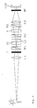
- the objects in the field of view such as e.g. the sun and a person or a house, as in the known device just described also first by means of a first lens L1 from one or more lenses on the substantially in the image plane of the lens L1 located photoconductive layer PC of a liquid crystal modulator of the prior Technique known type described above, which in turn is arranged between two polarizers P1 and P2.
- This intermediate image of the object field is now according to the invention waiving the required in the prior art second intermediate image by means of a downstream second objective L2 directly or via an optical fiber plate (light guide plate) on an observation and / or recording device CCD, in which it is in the present Case is a CCD color video camera.
- the images of the person and the sun on the photoconductive layer PC of the liquid crystal modulator PC, LC are converted into voltage patterns which are transmitted to the downstream liquid crystal cell and reorient the liquid crystal film so as to be in communication with the polarizers P1 and P2 becomes locally transparent to low light intensities while locally darkening high light intensities.
- the color correction filter F thus compensates for the color distortion, the color temperature of the light sources in the object field and the color absorption of the liquid crystal modulator, the polarizers P1 and P2 and the other optical assemblies. He must therefore be matched to the components of the camera.
- a mosaic color filter MF is arranged.
- a switch or a closure V of the type mentioned is for example from the above German Patent Application 196 16 323.4 by L. Beresnev et al , known.
- the shutter V can also be formed as another electro-optical or electromechanical shutter or switch, as are known in the prior art.
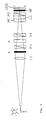
- the closure V can also be at another point of the optical system, such as to be disposed between the first lens L1 and the liquid crystal modulator PC, LC, so as in the illustrated in FIG. 3 embodiment of the invention is the case.
- the intermediate image shown in FIGS. 1 and 2 on the photoconductive layer PC of the liquid crystal modulator PC, LC is not absolutely necessary in video cameras, since with them in contrast to the eye except for a few Micrometer may approach the photosensitive plane of the video camera, ie the CCD camera chip, although this intermediate image may also be advantageous for video cameras for the purpose of magnification.
- FIG. 3 A corresponding embodiment of the invention without intermediate image is shown in Fig. 3, in which the entire package of the liquid crystal modulator PC, LC, the downstream polarizer P2 and the mosaic filter MF is placed in close proximity in front of the photosensitive layer CCD, while in turn between two Polarizers P3 and P2 arranged shutter V between the imaging lens L1 and the photoconductive layer PC of the liquid crystal modulator PC, LC.
- the image of the objects located in the field of view takes place directly on the CCD layer arranged substantially in the image plane of the objective L1 without an intermediate image on the photoconductive layer PC of the liquid crystal modulator, as in the embodiment according to the invention shown in FIG PC, LC or even a further intermediate image as would be necessary in the prior art.
- the image of the sun on the photoconductive layer PC is then not quite sharp, but this is irrelevant, since it is suppressed anyway.
- This arrangement according to the invention thus even has the advantage that light sources of disturbing light and backgrounds are not only darkened but also washed out.
Landscapes
- Engineering & Computer Science (AREA)
- Multimedia (AREA)
- Signal Processing (AREA)
- Liquid Crystal (AREA)
- Photometry And Measurement Of Optical Pulse Characteristics (AREA)
Claims (8)
- Dispositif d'affaiblissement local de l'intensité lumineuse dans le champ de vue d'un système d'observation et/ou d'enregistrement (CCD) photosensible comportant un premier objectif (L1) constitué d'une ou de plusieurs lentilles et un modulateur à cristaux liquides (PC, LC) ferroélectrique à résolution locale disposé entre deux polarisateurs (P1, P2) comprenant une couche photoconductrice (PC) et, en aval de celle-ci, une cellule à cristaux liquide (LC) de type smectique hélicoïdal qui est en contact avec ladite couche, et disposé de manière telle que la couche photoconductrice (PC) se trouve dans le plan de l'image du premier objectif (L1), le champ d'image du premier objectif (L1) étant projeté, par un second objectif (L2) constitué d'une ou de plusieurs lentilles, sur le système d'observation et/ou d'enregistrement (CCD),
caractérisé par
un filtre correcteur de couleur (F) destiné à compenser la contamination de la couleur due à la température de couleur des sources lumineuses dans le champ de l'objet et à l'absorption de couleur par les composants optiques. - Dispositif d'affaiblissement local de l'intensité lumineuse dans le champ de vue d'un système d'observation et/ou d'enregistrement (CCD) photosensible comportant un objectif (L1) constitué d'une ou de plusieurs lentilles et un modulateur à cristaux liquides (PC, LC) ferroélectrique à résolution locale disposé entre deux polarisateurs (P1, P2) dans le trajet des rayons de l'objectif et comprenant une couche photoconductrice (PC) et, en aval de celle-ci, une cellule à cristaux liquides (LC) de type smectique hélicoïdal qui est en contact avec ladite couche, le système d'observation et/ou d'enregistrement (CCD) doté, en amont, du modulateur à cristaux liquides (PC, LC) étant disposé dans le plan de l'image de l'objectif (L1),
caractérisé par un filtre correcteur de couleur (F) destiné à compenser la contamination de la couleur due à la température de couleur des sources lumineuses dans le champ de l'objet et à l'absorption de couleur par les composants optiques. - Dispositif selon la revendication 2,
caractérisé par une plaque de fibres optiques disposée entre le modulateur à cristaux liquides (PC, LC) et le système d'observation et/ou d'enregistrement (CCD). - Dispositif selon l'une des revendications 1 à 3, caractérisé en ce qu'un filtre de couleur mosaïque (MF) est prévu en amont du système d'observation et d'enregistrement (CCD) photosensible.
- Dispositif selon l'une des revendications 1 à 4,
caractérisé par
un obturateur optique (V) destiné à interrompre le trajet des rayons lorsque le modulateur à cristaux liquides (PC, LC) ne présente pas les caractéristiques réductrices d'éblouissement souhaitées. - Dispositif selon la revendication 5,
caractérisé en ce que
l'obturateur (V) est réalisé sous la forme d'un interrupteur rapide à cristaux liquides ferroélectrique ou d'un autre type d'interrupteur électro-optique ou électromécanique. - Dispositif selon la revendication 5 ou 6, caractérisé en ce que l'obturateur (V) est réalisé sous la forme d'une plaque de retardement commutable.
- Dispositif selon l'une des revendications 5 à 7, caractérisé en ce que
l'obturateur (V) est disposé entre deux polarisateurs (P3, P1; P2, P3).
Applications Claiming Priority (2)
| Application Number | Priority Date | Filing Date | Title |
|---|---|---|---|
| DE19815337 | 1998-04-06 | ||
| DE19815337A DE19815337C2 (de) | 1998-04-06 | 1998-04-06 | Vorrichtung zur lokalen Abschwächung der Lichtintensität im Sehfeld einer lichtempfindlichen Beobachtungseinrichtung |
Publications (2)
| Publication Number | Publication Date |
|---|---|
| EP0949810A1 EP0949810A1 (fr) | 1999-10-13 |
| EP0949810B1 true EP0949810B1 (fr) | 2007-11-07 |
Family
ID=7863732
Family Applications (1)
| Application Number | Title | Priority Date | Filing Date |
|---|---|---|---|
| EP99104510A Expired - Lifetime EP0949810B1 (fr) | 1998-04-06 | 1999-03-06 | Dispositif d'affaiblissement local de l'intensité lumineuse dans le champ de vue d'un appareil d'observation photosensible |
Country Status (5)
| Country | Link |
|---|---|
| US (1) | US6636278B1 (fr) |
| EP (1) | EP0949810B1 (fr) |
| AT (1) | ATE377907T1 (fr) |
| CA (1) | CA2267843A1 (fr) |
| DE (2) | DE19815337C2 (fr) |
Families Citing this family (9)
| Publication number | Priority date | Publication date | Assignee | Title |
|---|---|---|---|---|
| US7173662B1 (en) * | 2001-04-30 | 2007-02-06 | Massachusetts Institute Of Technology | Foveating imaging system and method employing a spatial light modulator to selectively modulate an input image |
| DE10155622A1 (de) * | 2001-11-13 | 2003-05-28 | Siemens Ag | Lichterfassungsvorrichtung mit Belichtungssteuerung |
| US20060215076A1 (en) * | 2005-03-22 | 2006-09-28 | Karim John H | Selective light transmitting and receiving system and method |
| US7755720B2 (en) * | 2005-05-10 | 2010-07-13 | Live Technologies, Ltd | Electro-optical filter |
| DE102005032111A1 (de) * | 2005-07-07 | 2007-01-11 | Jos. Schneider Optische Werke Gmbh | Homogenisieren eines horizontalen Verlaufs einer relativen Helligkeit eines Bildes |
| US7729607B2 (en) * | 2006-05-31 | 2010-06-01 | Technologies4All, Inc. | Camera glare reduction system and method |
| KR100887184B1 (ko) * | 2007-05-09 | 2009-03-10 | 한국과학기술원 | 부분 경면 물체의 형상측정 장치 및 그 방법 |
| JP2015026937A (ja) * | 2013-07-25 | 2015-02-05 | ソニー株式会社 | 撮像装置および撮像方法、並びにプログラム |
| US20150156382A1 (en) * | 2013-12-03 | 2015-06-04 | Chung-Shan Institute Of Science And Technology, Armaments Bureau, M.N.D | Multi-channel glare-suppression device of a digital image system |
Family Cites Families (32)
| Publication number | Priority date | Publication date | Assignee | Title |
|---|---|---|---|---|
| US3661442A (en) | 1969-03-25 | 1972-05-09 | Hitachi Ltd | Electrically operated optical shutter |
| GB1425920A (en) * | 1972-11-09 | 1976-02-25 | Nat Res Dev | Optical intensity adjustment devices |
| US4272164A (en) * | 1979-06-22 | 1981-06-09 | The United States Of America As Represented By The Secretary Of The Army | Bright source attenuating device for an image intensifier |
| JPS58134578A (ja) | 1982-02-05 | 1983-08-10 | Nippon Kogaku Kk <Nikon> | テレビジヨンカメラ用フイルタ装置 |
| US4462661A (en) | 1982-02-23 | 1984-07-31 | Instrument Flight Research | Laser protection goggles |
| HUT36381A (en) | 1982-10-04 | 1985-09-30 | Zeiss Jena Veb Carl | Anti-dazzle spectacles |
| DE3437704A1 (de) | 1984-01-02 | 1985-07-11 | Jenoptik Jena Gmbh, Ddr 6900 Jena | Empfaengereinheit fuer eine blendschutzbrille |
| JPS6227717A (ja) * | 1985-07-29 | 1987-02-05 | Nissan Motor Co Ltd | 撮像装置 |
| FR2611389B1 (fr) | 1987-02-27 | 1989-04-28 | Thomson Csf | Dispositif imageur matriciel a cristaux liquides a resolution doublee par birefringence |
| DE3721751A1 (de) | 1987-07-01 | 1989-01-12 | Eps Elektronik | Optoelektronisches filter vorzugsweise fuer videokameras |
| FR2626385B1 (fr) | 1988-01-22 | 1991-10-11 | Thomson Csf | Obturateur selectif de lumiere, procede de realisation et son application a un detecteur d'image |
| JP2738724B2 (ja) | 1988-11-25 | 1998-04-08 | 松下電器産業株式会社 | 空間光変調素子及び神経ネットワーク回路 |
| FR2655163A1 (fr) | 1989-11-30 | 1991-05-31 | Scanera Ste Civile Rech | Dispositif de visualisation en faibles eclairements a couches de materiaux photo-electriques et electro-optiques. |
| US5126866A (en) * | 1989-08-11 | 1992-06-30 | Sharp Kabushiki Kaisha | Liquid crystal display with a plurality of phase difference plates the slow axes of which form an angle of 20 to 40 degrees |
| FR2661755B1 (fr) | 1990-05-02 | 1992-07-03 | Thomson Csf | Modulateur spatial de lumiere a base de polymere photoconducteur. |
| US5073010A (en) | 1990-05-11 | 1991-12-17 | University Of Colorado Foundation, Inc. | Optically addressable spatial light modulator having a distorted helix ferroelectric liquid crystal member |
| JP3010392B2 (ja) | 1991-07-08 | 2000-02-21 | セイコーインスツルメンツ株式会社 | 空間光変調器とその駆動方法 |
| US5418546A (en) * | 1991-08-20 | 1995-05-23 | Mitsubishi Denki Kabushiki Kaisha | Visual display system and exposure control apparatus |
| US5212555A (en) * | 1991-12-17 | 1993-05-18 | Texas Instruments Incorporated | Image capture with spatial light modulator and single-cell photosensor |
| US5384649A (en) * | 1991-12-26 | 1995-01-24 | Matsushita Electric Industrial Co., Ltd. | Liquid crystal spatial light modulator with electrically isolated reflecting films connected to electrically isolated pixel portions of photo conductor |
| JP3241432B2 (ja) * | 1992-05-22 | 2001-12-25 | パイオニア株式会社 | 温度変化検出機能を有する光導電型液晶ライトバルブ表示装置 |
| JPH0619106A (ja) * | 1992-07-01 | 1994-01-28 | Toppan Printing Co Ltd | 画像露光方法及び画像露光装置 |
| JPH06148593A (ja) * | 1992-11-11 | 1994-05-27 | Canon Inc | 光量調整装置を有した光学系 |
| US5353080A (en) | 1992-11-02 | 1994-10-04 | Christman Ernest H | Exposure-equalizing system for photographic images |
| DE4305807A1 (de) | 1993-02-25 | 1994-10-13 | Thomson Brandt Gmbh | Kamera mit einer steuerbaren Blende |
| CH687809A5 (de) | 1993-05-14 | 1997-02-28 | Xelux Holding Ag | Blendschutzvorrichtung. |
| JP2738906B2 (ja) * | 1993-11-25 | 1998-04-08 | 浜松ホトニクス株式会社 | 照合装置 |
| CH686214A5 (de) | 1994-04-22 | 1996-02-15 | Xelux Holding Ag | Blendschutzvorrichtung. |
| DE19616323A1 (de) * | 1996-04-24 | 1997-10-30 | Deutsche Telekom Ag | Vorrichtung zur lokalen Abschwächung der Lichtintensität |
| DE19623835C2 (de) * | 1996-06-14 | 1999-09-23 | Agfa Gevaert Ag | Verfahren und Vorrichtung zum Belichten von fotografischem Aufzeichnungsmaterial sowie fotografisches Kopiergerät |
| GB2327797A (en) * | 1997-07-31 | 1999-02-03 | Sharp Kk | Spatial light modulator and display |
| US6204901B1 (en) * | 1997-07-31 | 2001-03-20 | Duke University | Liquid crystal color shutters that include reflective polarizers that pass color components of light of a first polarization and that reflect a majority of color components of light of a second polarization |
-
1998
- 1998-04-06 DE DE19815337A patent/DE19815337C2/de not_active Expired - Fee Related
-
1999
- 1999-03-06 DE DE59914543T patent/DE59914543D1/de not_active Expired - Lifetime
- 1999-03-06 EP EP99104510A patent/EP0949810B1/fr not_active Expired - Lifetime
- 1999-03-06 AT AT99104510T patent/ATE377907T1/de not_active IP Right Cessation
- 1999-04-01 CA CA002267843A patent/CA2267843A1/fr not_active Abandoned
- 1999-04-06 US US09/286,882 patent/US6636278B1/en not_active Expired - Fee Related
Also Published As
| Publication number | Publication date |
|---|---|
| DE19815337C2 (de) | 2001-07-05 |
| ATE377907T1 (de) | 2007-11-15 |
| EP0949810A1 (fr) | 1999-10-13 |
| DE59914543D1 (de) | 2007-12-20 |
| US6636278B1 (en) | 2003-10-21 |
| DE19815337A1 (de) | 1999-10-07 |
| CA2267843A1 (fr) | 1999-10-06 |
Similar Documents
| Publication | Publication Date | Title |
|---|---|---|
| EP0662274B1 (fr) | Systeme de projection d'images video en couleurs et elements optiques de transformation correspondants | |
| DE69019712T2 (de) | Augenschutzbrille mit Flüssigkristall-Lichtventil. | |
| DE69834234T2 (de) | Zusammengesetzte Anzeigevorrichtung | |
| AT399232B (de) | Mikroskop mit bildhelligkeitsabgleich | |
| DE68909641T2 (de) | Projektionsdarstellungsgerät. | |
| DE69027196T2 (de) | Flüssigkristallanzeige mit faseroptischer Frontplatte | |
| EP0949810B1 (fr) | Dispositif d'affaiblissement local de l'intensité lumineuse dans le champ de vue d'un appareil d'observation photosensible | |
| EP1217413A2 (fr) | Dispositif optique d'observation avec signal optique superposé | |
| DE3729512A1 (de) | Projektionseinrichtung | |
| DE4417762C1 (de) | Vorrichtung und Verfahren zum Projizieren und Empfangen von Bildinformation mittels eines Bildschirms | |
| DE3708959C2 (de) | Schweissüberwachungsvorrichtung | |
| DE2645010A1 (de) | Farbfernsehkamera | |
| DE69123628T2 (de) | Bildanzeige- und -aufnahmegerät | |
| DE69331647T2 (de) | Lichtventilvorrichtung und Anzeigesystem, das diese benutzt | |
| DE102016004842A1 (de) | Bildschirm und Verfahren für einen freien und einen eingeschränkten Sichtmodus | |
| EP0534150A1 (fr) | Limitation de l'hyperluminosité pour un appareil de vision nocturne | |
| DE888562C (de) | Einrichtung zur Wiedergabe von Fernsehbildern | |
| DE102018102468A1 (de) | Okular zur virtuellen Abbildung eines Bildes sowie Abbildungsvorrichtung mit einem solchen Okular | |
| WO1998056186A1 (fr) | Dispositif pour moduler l'intensite d'un faisceau lumineux, procede permettant de produire ledit dispositif, procede pour moduler l'intensite d'un faisceau lumineux et utilisation dudit dispositif | |
| DE3312362C1 (de) | Gerät mit einem in der Helligkeit regelbaren Bildschirm und/oder Anzeigdisplay | |
| DE69415953T2 (de) | Bildprojektion mit optisch angesteuertem Lichtmodulator | |
| DE69017188T2 (de) | Projektionsanzeigevorrichtung. | |
| DE69733867T2 (de) | Am kopf befestigte anzeigevorrichtung | |
| DE102006030273A1 (de) | Abbilden optischer Bilder auf einen Bildsensor mittels einer faseroptischen Platte bzw. eines Faserkeils | |
| DE2240332A1 (de) | Kamera, insbesondere fernsehkamera |
Legal Events
| Date | Code | Title | Description |
|---|---|---|---|
| PUAI | Public reference made under article 153(3) epc to a published international application that has entered the european phase |
Free format text: ORIGINAL CODE: 0009012 |
|
| AK | Designated contracting states |
Kind code of ref document: A1 Designated state(s): AT BE CH CY DE DK ES FI FR GB GR IE IT LI LU MC NL PT SE |
|
| AX | Request for extension of the european patent |
Free format text: AL;LT;LV;MK;RO;SI |
|
| 17P | Request for examination filed |
Effective date: 20000413 |
|
| AKX | Designation fees paid |
Free format text: AT BE CH CY DE DK ES FI FR GB GR IE IT LI LU MC NL PT SE |
|
| GRAP | Despatch of communication of intention to grant a patent |
Free format text: ORIGINAL CODE: EPIDOSNIGR1 |
|
| GRAS | Grant fee paid |
Free format text: ORIGINAL CODE: EPIDOSNIGR3 |
|
| GRAA | (expected) grant |
Free format text: ORIGINAL CODE: 0009210 |
|
| AK | Designated contracting states |
Kind code of ref document: B1 Designated state(s): AT BE CH CY DE DK ES FI FR GB GR IE IT LI LU MC NL PT SE |
|
| REG | Reference to a national code |
Ref country code: GB Ref legal event code: FG4D Free format text: NOT ENGLISH |
|
| REG | Reference to a national code |
Ref country code: IE Ref legal event code: FG4D Free format text: LANGUAGE OF EP DOCUMENT: GERMAN |
|
| REG | Reference to a national code |
Ref country code: CH Ref legal event code: EP |
|
| REF | Corresponds to: |
Ref document number: 59914543 Country of ref document: DE Date of ref document: 20071220 Kind code of ref document: P |
|
| GBT | Gb: translation of ep patent filed (gb section 77(6)(a)/1977) |
Effective date: 20080130 |
|
| PG25 | Lapsed in a contracting state [announced via postgrant information from national office to epo] |
Ref country code: SE Free format text: LAPSE BECAUSE OF FAILURE TO SUBMIT A TRANSLATION OF THE DESCRIPTION OR TO PAY THE FEE WITHIN THE PRESCRIBED TIME-LIMIT Effective date: 20080207 Ref country code: NL Free format text: LAPSE BECAUSE OF FAILURE TO SUBMIT A TRANSLATION OF THE DESCRIPTION OR TO PAY THE FEE WITHIN THE PRESCRIBED TIME-LIMIT Effective date: 20071107 Ref country code: ES Free format text: LAPSE BECAUSE OF FAILURE TO SUBMIT A TRANSLATION OF THE DESCRIPTION OR TO PAY THE FEE WITHIN THE PRESCRIBED TIME-LIMIT Effective date: 20080218 |
|
| NLV1 | Nl: lapsed or annulled due to failure to fulfill the requirements of art. 29p and 29m of the patents act | ||
| ET | Fr: translation filed | ||
| PG25 | Lapsed in a contracting state [announced via postgrant information from national office to epo] |
Ref country code: DK Free format text: LAPSE BECAUSE OF FAILURE TO SUBMIT A TRANSLATION OF THE DESCRIPTION OR TO PAY THE FEE WITHIN THE PRESCRIBED TIME-LIMIT Effective date: 20071107 |
|
| PLBE | No opposition filed within time limit |
Free format text: ORIGINAL CODE: 0009261 |
|
| STAA | Information on the status of an ep patent application or granted ep patent |
Free format text: STATUS: NO OPPOSITION FILED WITHIN TIME LIMIT |
|
| BERE | Be: lapsed |
Owner name: DEUTSCHE TELEKOM A.G. Effective date: 20080331 |
|
| PG25 | Lapsed in a contracting state [announced via postgrant information from national office to epo] |
Ref country code: PT Free format text: LAPSE BECAUSE OF FAILURE TO SUBMIT A TRANSLATION OF THE DESCRIPTION OR TO PAY THE FEE WITHIN THE PRESCRIBED TIME-LIMIT Effective date: 20080407 |
|
| REG | Reference to a national code |
Ref country code: IE Ref legal event code: FD4D |
|
| 26N | No opposition filed |
Effective date: 20080808 |
|
| PG25 | Lapsed in a contracting state [announced via postgrant information from national office to epo] |
Ref country code: MC Free format text: LAPSE BECAUSE OF NON-PAYMENT OF DUE FEES Effective date: 20080331 Ref country code: IE Free format text: LAPSE BECAUSE OF FAILURE TO SUBMIT A TRANSLATION OF THE DESCRIPTION OR TO PAY THE FEE WITHIN THE PRESCRIBED TIME-LIMIT Effective date: 20071107 |
|
| REG | Reference to a national code |
Ref country code: CH Ref legal event code: PL |
|
| PG25 | Lapsed in a contracting state [announced via postgrant information from national office to epo] |
Ref country code: LI Free format text: LAPSE BECAUSE OF NON-PAYMENT OF DUE FEES Effective date: 20080331 Ref country code: GR Free format text: LAPSE BECAUSE OF FAILURE TO SUBMIT A TRANSLATION OF THE DESCRIPTION OR TO PAY THE FEE WITHIN THE PRESCRIBED TIME-LIMIT Effective date: 20080208 Ref country code: CH Free format text: LAPSE BECAUSE OF NON-PAYMENT OF DUE FEES Effective date: 20080331 |
|
| PG25 | Lapsed in a contracting state [announced via postgrant information from national office to epo] |
Ref country code: FI Free format text: LAPSE BECAUSE OF FAILURE TO SUBMIT A TRANSLATION OF THE DESCRIPTION OR TO PAY THE FEE WITHIN THE PRESCRIBED TIME-LIMIT Effective date: 20071107 Ref country code: BE Free format text: LAPSE BECAUSE OF NON-PAYMENT OF DUE FEES Effective date: 20080331 |
|
| PG25 | Lapsed in a contracting state [announced via postgrant information from national office to epo] |
Ref country code: CY Free format text: LAPSE BECAUSE OF FAILURE TO SUBMIT A TRANSLATION OF THE DESCRIPTION OR TO PAY THE FEE WITHIN THE PRESCRIBED TIME-LIMIT Effective date: 20071107 |
|
| PG25 | Lapsed in a contracting state [announced via postgrant information from national office to epo] |
Ref country code: AT Free format text: LAPSE BECAUSE OF NON-PAYMENT OF DUE FEES Effective date: 20080306 |
|
| PG25 | Lapsed in a contracting state [announced via postgrant information from national office to epo] |
Ref country code: LU Free format text: LAPSE BECAUSE OF NON-PAYMENT OF DUE FEES Effective date: 20080306 |
|
| PG25 | Lapsed in a contracting state [announced via postgrant information from national office to epo] |
Ref country code: IT Free format text: LAPSE BECAUSE OF NON-PAYMENT OF DUE FEES Effective date: 20080331 |
|
| PGFP | Annual fee paid to national office [announced via postgrant information from national office to epo] |
Ref country code: GB Payment date: 20130318 Year of fee payment: 15 Ref country code: DE Payment date: 20130320 Year of fee payment: 15 Ref country code: FR Payment date: 20130329 Year of fee payment: 15 |
|
| REG | Reference to a national code |
Ref country code: DE Ref legal event code: R119 Ref document number: 59914543 Country of ref document: DE |
|
| GBPC | Gb: european patent ceased through non-payment of renewal fee |
Effective date: 20140306 |
|
| REG | Reference to a national code |
Ref country code: FR Ref legal event code: ST Effective date: 20141128 |
|
| REG | Reference to a national code |
Ref country code: DE Ref legal event code: R119 Ref document number: 59914543 Country of ref document: DE Effective date: 20141001 |
|
| PG25 | Lapsed in a contracting state [announced via postgrant information from national office to epo] |
Ref country code: FR Free format text: LAPSE BECAUSE OF NON-PAYMENT OF DUE FEES Effective date: 20140331 Ref country code: DE Free format text: LAPSE BECAUSE OF NON-PAYMENT OF DUE FEES Effective date: 20141001 Ref country code: GB Free format text: LAPSE BECAUSE OF NON-PAYMENT OF DUE FEES Effective date: 20140306 |