EP0950378A1 - Appareil pour l'épilation électrolitique - Google Patents
Appareil pour l'épilation électrolitique Download PDFInfo
- Publication number
- EP0950378A1 EP0950378A1 EP99107170A EP99107170A EP0950378A1 EP 0950378 A1 EP0950378 A1 EP 0950378A1 EP 99107170 A EP99107170 A EP 99107170A EP 99107170 A EP99107170 A EP 99107170A EP 0950378 A1 EP0950378 A1 EP 0950378A1
- Authority
- EP
- European Patent Office
- Prior art keywords
- needle
- assembly
- head assembly
- plug
- needle head
- Prior art date
- Legal status (The legal status is an assumption and is not a legal conclusion. Google has not performed a legal analysis and makes no representation as to the accuracy of the status listed.)
- Withdrawn
Links
- 238000005868 electrolysis reaction Methods 0.000 title claims abstract description 22
- 210000004209 hair Anatomy 0.000 title claims abstract description 13
- 230000001681 protective effect Effects 0.000 claims abstract description 44
- 210000004207 dermis Anatomy 0.000 claims abstract description 10
- 210000004919 hair shaft Anatomy 0.000 claims abstract description 9
- 208000002193 Pain Diseases 0.000 claims abstract description 8
- 210000003780 hair follicle Anatomy 0.000 claims abstract description 6
- 208000019300 CLIPPERS Diseases 0.000 claims description 17
- 208000021930 chronic lymphocytic inflammation with pontine perivascular enhancement responsive to steroids Diseases 0.000 claims description 17
- 239000000463 material Substances 0.000 claims description 5
- 241000602850 Cinclidae Species 0.000 claims description 2
- 201000010099 disease Diseases 0.000 description 4
- 208000037265 diseases, disorders, signs and symptoms Diseases 0.000 description 4
- 239000008280 blood Substances 0.000 description 3
- 210000004369 blood Anatomy 0.000 description 3
- 239000011521 glass Substances 0.000 description 3
- 208000027418 Wounds and injury Diseases 0.000 description 2
- 230000006378 damage Effects 0.000 description 2
- 208000014674 injury Diseases 0.000 description 2
- 238000003780 insertion Methods 0.000 description 2
- 230000037431 insertion Effects 0.000 description 2
- 210000003491 skin Anatomy 0.000 description 2
- 208000030507 AIDS Diseases 0.000 description 1
- 229910000831 Steel Inorganic materials 0.000 description 1
- 239000011324 bead Substances 0.000 description 1
- 230000005540 biological transmission Effects 0.000 description 1
- 238000010276 construction Methods 0.000 description 1
- 208000006454 hepatitis Diseases 0.000 description 1
- 231100000283 hepatitis Toxicity 0.000 description 1
- 238000009434 installation Methods 0.000 description 1
- 239000002184 metal Substances 0.000 description 1
- 238000000034 method Methods 0.000 description 1
- 230000002441 reversible effect Effects 0.000 description 1
- 239000010959 steel Substances 0.000 description 1
Images



Classifications
-
- A—HUMAN NECESSITIES
- A61—MEDICAL OR VETERINARY SCIENCE; HYGIENE
- A61B—DIAGNOSIS; SURGERY; IDENTIFICATION
- A61B18/00—Surgical instruments, devices or methods for transferring non-mechanical forms of energy to or from the body
- A61B18/04—Surgical instruments, devices or methods for transferring non-mechanical forms of energy to or from the body by heating
- A61B18/12—Surgical instruments, devices or methods for transferring non-mechanical forms of energy to or from the body by heating by passing a current through the tissue to be heated, e.g. high-frequency current
- A61B18/14—Probes or electrodes therefor
-
- A—HUMAN NECESSITIES
- A61—MEDICAL OR VETERINARY SCIENCE; HYGIENE
- A61B—DIAGNOSIS; SURGERY; IDENTIFICATION
- A61B18/00—Surgical instruments, devices or methods for transferring non-mechanical forms of energy to or from the body
- A61B2018/00315—Surgical instruments, devices or methods for transferring non-mechanical forms of energy to or from the body for treatment of particular body parts
- A61B2018/00452—Skin
-
- A—HUMAN NECESSITIES
- A61—MEDICAL OR VETERINARY SCIENCE; HYGIENE
- A61B—DIAGNOSIS; SURGERY; IDENTIFICATION
- A61B18/00—Surgical instruments, devices or methods for transferring non-mechanical forms of energy to or from the body
- A61B2018/00315—Surgical instruments, devices or methods for transferring non-mechanical forms of energy to or from the body for treatment of particular body parts
- A61B2018/00452—Skin
- A61B2018/00476—Hair follicles
Definitions
- the present invention relates to the combination of an handle, a needle head assembly and a protective cover for use in an hair removal electrolysis apparatus.
- Free needles are free and delicate components to be manipulated with tweezers.
- Most handles adapted to free needles comprise a separate molded tip used to tighten radial slot of the plug of the handle on the needle itself.
- the molded tip can be a reusable one which must be sterilised between each use, or a disposable one.
- Refined free needles use axial spring forces to enhance the electrical contact between the needle and the plug.
- these refined needles are dangerous because the tip may accidentally detached and the needle is propelled by the spring, eventually causing injury to the operator.
- the third type of handle and needles system such as described in US 4,785,808 (Cary), has a fine metallic wire, molded-in inside a threaded plastic head and a cap to protect the needle.
- This system uses no steel shaft and it does not provide a great electric contact between the needle and the handle. It also does not connect the needle shaft to the handle tightly and securely.
- the electrolysis process may entail contact with the patient and/or operator blood during insertion of the needle alongside the hairshaft in the dermis of the patient, or inadvertent hinging when the operator removes the hair from the dermis with tweezers or fixes the magnifying glass or other manipulation of the type or inadvertent movement of the patient.
- a sterile needle head assembly which can be quickly and safely installed on the handle without having to remove the protective cover which then acts as a handling means, or quickly and safely removed from the handle without having to remove the protective cover which then acts as a safety means for stockage.
- a first object of the present invention is to provide an apparatus of very specific construction, which satisfies the above mentioned needs in the hair removal electrolysis field.
- the first object of the invention is to provide an apparatus wherein the needle head assembly can be quickly and safely inserted or removed from the handle, by hand, without need of tweezers, while being covered by the protective cover.
- Another object of the invention is to provide an apparatus of the above type wherein a good electrical contact is achieved between the needle and the electrical supply forming part of the electrolysis apparatus.
- the handle comprises a sleeve, a plug and a wire.
- the sleeve is elongated and electrically insulated and it has a main axis and two opposite ends.
- the plug is electrically conductive and is coaxial with the sleeve. It projects from one of the opposite ends of the sleeve and has an axial hole.
- the wire is electrically conductive and extends from the plug through the sleeve. It projects out from the other end of the sleeve for connection to an electric supply forming part of an electrolysis apparatus.
- the needle head assembly comprises a head cap and a needle assembly.
- the head cap has an open cavity sized and is shaped to receive the plug. As a result, the head cap can externally fit onto the plug of the handle, or alternatively, on the handle itself.
- the needle assembly is fixed to the head cap. It comprises a connecting pin extending within the cavity of the head cap so as to snugly fit into the hole of the plug and thus to be electrically connected to the electric supply.
- the needle assembly also comprises a needle axially projecting from the connecting pin outwards the head cap.
- the needle is sized to be inserted into the hair follicle of a patient along side a hair shaft in the dermis, so that electrical current can be dispensed through the needle below the surface of the skin, alongside a hair shaft, in the dermis, right up to the hair bulb.
- the protective cover is sized and shaped to snugly fit onto the head cap in order to cover the needle projecting axially out of the head cap and thus to avoid inadvertent breaking of the needle during stockage or accidental stinging during handling.
- first and second attachment means are provided on the head cap and the handle, respectively. These attachment means are operatively connectable to each other, in order to detachably connect from each other.
- the attachment means may be of any type provided that they allow detachable connection of the head cap onto the handle by means of the protective cover. These attachment means may be, for example, a screw type mount, a bayonet type mount or a clip-on type mount.
- the plug on the handle has an axial slot extending through its axial hole. This slot facilitates insertion of the connecting pin of the needle head assembly into the plug and provides a better electrical contact between the pin and the plug.
- the needle head assembly and protective cover are of the disposable type.
- the invention provides the combination of a handle, a needle head assembly and a protective cover which makes it unlikely not to say impossible to have a transmission of disease via the human blood.
- the invention also lies in the needle head assembly as such, which is of a disposable type and can fit on already existing handles.
- This needle head assembly comprises a head cap and a needle assembly.
- the head cap has an open cavity sized and is shaped to receive the plug of the handle, whereby said head cap can externally fit onto the handle, preferably onto the plug of the handle.
- the needle assembly is fixed to the head cap. It comprises a connecting pin extending within the cavity of the head cap so as to snugly fit into the hole of the plug and thus to be electrically connected to the electric supply. It also comprises a needle axially projecting the connecting pin outwards the head cap.
- the needle is sized to be inserted into the hair follicle of a patient along side a hair shaft in the dermis.
- the needle projecting axially out of the head cap can be protected by the protective cover sized and shaped to snugly fit onto the head cap and thus to avoid inadvertent breaking of the needle during stockage or accidental stinging during handling.
- the invention lies in the combination of a handle, a sterile needle head assembly and a needle protective cover, which is devised to allow the installation of the needle head assembly onto the handle by hand, without need of tweezers, and without having to remove the protective covering, thereby reducing the risk of damaging the needle or getting sting by it.
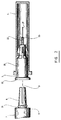
- the combination 1 according to a first preferred embodiment of the invention is shown in Fig. 1. It comprises a handle 2 having an elongated electrically insulated sleeve 5 with a smooth outer surface, an electrically conductive plug 6 and an electrically conductive wire 7.
- the insulated sleeve 5 has a main axis 9 and two opposite ends 10 and 11.
- the electrically conductive plug 6 is coaxial with the main axis 9 of the sleeve 5 and has an axial hole 13 and a radial slot 14 (see Fig. 3a). It is rigidly attached to the end 11 of the sleeve and has a base portion 31 adjacent to this one end 11.
- the electrically conductive wire 7 extends from the plug 6 through the sleeve 5 and projects out from the opposite end 10 of the sleeve 5 for connection to an electric supply 15 forming part of a hair removal electrolysis apparatus 17.
- the surface of the handle needs not be smooth. As a matter of fact, it may comprise protruding or recessed surfaces to enhance comfort when the handle is held for long periods of time.
- the electrically conductive wire 7 needs not to project out of the end 10 of the sleeve 5 but may rather extend from one side 18 of the handle.
- This bend of the wire 7 on the handle 2 allows much enhanced comfort during handle manipulation in a working position behind any type of magnifying glass commonly used in this field.
- the magnifying glass can be held a few inches closer to the patient treated area, when compared to a straight wire connection.
- the combination 1 also comprises a needle head assembly 3 comprising a head cap 20 which is made of plastic material, and a needle assembly 22 which is made of a conductive metal.
- the head cap 20 has an open cavity 23 that is sized and shaped to receive the plug 6.
- the needle assembly 22 is fixed to the head cap 20 and comprises a connecting pin 25 and a needle 27.
- the connecting pin 25 extends in the open cavity 23 of the head cap 20 and snugly fits in the hole 13 of the plug 6.
- the radial slot 14 enables to insert the connecting pin 25 easily in the plug 6 and to maintain a good electrical contact between the pin 25 and the plug 6.
- the connecting pin 25 is then electrically connected to the electric supply 15 of the hair removal electrolysis apparatus 17.
- the needle 27 projects axially from the connecting pin 25 outwards the head cap 20 and is sized to be inserted into the hair follicle of a patient along side a hair shaft in the dermis. Electrical current can be dispensed through the needle below the surface of the skin, alongside a hair shaft, in the dermis, until the hair bulb.
- the size and dimensions of the needle head assembly are preserved in order to make it useable with commonly used handles.
- the combination 1 further comprises a protective cover 4 which is made of plastic material and is sized and shaped to snugly fit onto the head cap 20 in order to cover the needle 27 which projects axially out of the head cap 20.
- the purpose of the protective cover 4 is essentially to avoid inadvertent breaking of the needle 27 during stockage or accidental stinging during handling.
- the protective cover 4 is fit on the needle head assembly by friction means.
- the diameter of the open cavity of the protective cover is just a little bit larger than the diameter of the needle head assembly 3.
- the head cap 20 and the protective cover 4 are preferably made of plastic material and the needle head assembly 3 and the protective cover 4 are both of the disposable type.
- the above combination of the handle 2, the needle head assembly 3 and the protective cover 4 is improved in that attachment means are provided to detachably connect the needle head assembly to the handle.
- a first attachment means is provided on the head cap 20 of the needle head assembly 3 and a second attachment means is provided on the plug 6 of the handle 2, or, alternatively, on the handle 2 itself.
- These attachment means are operatively connectable to each other in order to detachably connect the head cap 20 to the handle 2.
- the open cavity 23 of the head cap 20 has an internal rim portion 30 on which the first attachment means is mounted.
- the second attachment means is externally mounted on the base portion 31 of the plug 6.
- the first and second attachment means consist of a screw type mount, viz, a set of cooperating threads.
- the needle head assembly 3 can be detachably connected to the plug 6 by screwing.
- the first and second attachment means consist of a bayonet type mount. More particularly, the first and second attachments comprise one or more locking pin 33 projecting radially outwardly from the base 31 of the plug 6 and a socket 34 mounted on the needle head assembly 3. Alternatively, the pin(s) could be mounted on the needle head assembly 3 so as to project radially inwardly within the open cavity 23 of the head cap and the socket 34 could be mounted on the plug 6.
- the needle head assembly 3 is connected on the plug 6 of the handle with a snap-on type mount like the one used in pens.
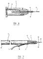
- the open cavity 23 of the head cap 20 comprises a circular recess 40 which is devised and shaped to "receive" a corresponding circular bulge 41 (see Fig. 7) projecting from the base 31 of the plug 6.
- the "snap-on" strength is selected so that the connection between the recess 40 and bulge 41 is stronger than the friction between the external surface of the head cap of the needle head assembly and the internal surface of the protective cover so that when the operator removes the needle head assembly from the handle, the protective cover stays on the needle head assembly unless he or she pinches the protective cover so hard that the friction between it and the head cap becomes stronger than the snap-on strength.
- the open cavity 23 of the head cap 20 has an external rim portion 30 on which the first attachment means is mounted.
- the second attachment means is externally mounted on the handle 2.
- the first and second attachment means consist of clip-on type mount.
- the needle head assembly 3 is attached to the handle 2 itself by clipping.
- the clip-on type mount comprises two pegs 37 and two clippers 38.
- the pegs 37 are mounted on the external rim portion 30 of the head cap 20 and the dippers 38 are mounted on the external rim portion 31 of the handle 2.
- Fig. 5a shows a cross section of the pegs 37.
- the pegs 37 could be mounted on the external rim portion 31 of the handle 2 and the clippers 38 on the external rim portion 30 of the head cap 20.
- the head cap 20 of the needle head assembly 3 has an external rim portion 80 on which is mounted the first attachment means.
- the second attachment means 81 is mounted on the end 11 of the sleeve 5 of the handle 2.
- the first and second attachment means consist of a screw type mount, wherein the needle head assembly 3 is attached to the plug 6 by screwing.
- the second attachment means can be either on the plug of the handle or the handle itself.
- the attachment means described as the first attachment means (on the needle head assembly) could be "inverted" with the second attachment means (on the handle) or vice-versa.
- the needle head assembly is sold with the protective cover already fit on so as to protect the needle from breaking and the operator from stinging.
- the operator can then hold the protective cover and connect the needle head assembly on the handle by means of the attachment means.
- the operator pulls out the protective cover and can start working.
- the operator can put back the protective cover on the needle by pushing it on the head cap and then use this cover as a tool to remove the needle head assembly from the handle, without stinging himself/ herself
- the needed head assembly can be disposed off together with the protection cover which still "embed” the needle and thus acts as a perfecty device.
Landscapes
- Health & Medical Sciences (AREA)
- Surgery (AREA)
- Engineering & Computer Science (AREA)
- Life Sciences & Earth Sciences (AREA)
- Biomedical Technology (AREA)
- Otolaryngology (AREA)
- Nuclear Medicine, Radiotherapy & Molecular Imaging (AREA)
- Plasma & Fusion (AREA)
- Physics & Mathematics (AREA)
- Heart & Thoracic Surgery (AREA)
- Medical Informatics (AREA)
- Molecular Biology (AREA)
- Animal Behavior & Ethology (AREA)
- General Health & Medical Sciences (AREA)
- Public Health (AREA)
- Veterinary Medicine (AREA)
- Measurement Of The Respiration, Hearing Ability, Form, And Blood Characteristics Of Living Organisms (AREA)
Applications Claiming Priority (2)
| Application Number | Priority Date | Filing Date | Title |
|---|---|---|---|
| CA2231383 | 1998-04-16 | ||
| CA 2231383 CA2231383A1 (fr) | 1998-04-16 | 1998-04-16 | Combinaison manche, assemblage de tete d'aiguille et capuchon d'aiguille pour emploi dans un appareil d'epilation par electrolyse |
Publications (1)
| Publication Number | Publication Date |
|---|---|
| EP0950378A1 true EP0950378A1 (fr) | 1999-10-20 |
Family
ID=4162183
Family Applications (1)
| Application Number | Title | Priority Date | Filing Date |
|---|---|---|---|
| EP99107170A Withdrawn EP0950378A1 (fr) | 1998-04-16 | 1999-04-13 | Appareil pour l'épilation électrolitique |
Country Status (2)
| Country | Link |
|---|---|
| EP (1) | EP0950378A1 (fr) |
| CA (1) | CA2231383A1 (fr) |
Cited By (33)
| Publication number | Priority date | Publication date | Assignee | Title |
|---|---|---|---|---|
| EP2100567A1 (fr) * | 2008-03-11 | 2009-09-16 | Tyco Healthcare Group, LP | Effecteur d'extrémité à découpe bipolaire |
| US7951150B2 (en) | 2005-01-14 | 2011-05-31 | Covidien Ag | Vessel sealer and divider with rotating sealer and cutter |
| US8034052B2 (en) | 2006-05-05 | 2011-10-11 | Covidien Ag | Apparatus and method for electrode thermosurgery |
| US8147489B2 (en) | 2005-01-14 | 2012-04-03 | Covidien Ag | Open vessel sealing instrument |
| US8197633B2 (en) | 2005-09-30 | 2012-06-12 | Covidien Ag | Method for manufacturing an end effector assembly |
| US8257352B2 (en) | 2003-11-17 | 2012-09-04 | Covidien Ag | Bipolar forceps having monopolar extension |
| US8348948B2 (en) | 2004-03-02 | 2013-01-08 | Covidien Ag | Vessel sealing system using capacitive RF dielectric heating |
| US8361072B2 (en) | 2005-09-30 | 2013-01-29 | Covidien Ag | Insulating boot for electrosurgical forceps |
| US8394095B2 (en) | 2005-09-30 | 2013-03-12 | Covidien Ag | Insulating boot for electrosurgical forceps |
| US8394096B2 (en) | 2003-11-19 | 2013-03-12 | Covidien Ag | Open vessel sealing instrument with cutting mechanism |
| US8454602B2 (en) | 2009-05-07 | 2013-06-04 | Covidien Lp | Apparatus, system, and method for performing an electrosurgical procedure |
| US8523898B2 (en) | 2009-07-08 | 2013-09-03 | Covidien Lp | Endoscopic electrosurgical jaws with offset knife |
| WO2013134908A1 (fr) * | 2012-03-11 | 2013-09-19 | Li Nong | Aiguille de thermocoagulation |
| US8551091B2 (en) | 2002-10-04 | 2013-10-08 | Covidien Ag | Vessel sealing instrument with electrical cutting mechanism |
| US8568444B2 (en) | 2008-10-03 | 2013-10-29 | Covidien Lp | Method of transferring rotational motion in an articulating surgical instrument |
| US8591506B2 (en) | 1998-10-23 | 2013-11-26 | Covidien Ag | Vessel sealing system |
| US8641713B2 (en) | 2005-09-30 | 2014-02-04 | Covidien Ag | Flexible endoscopic catheter with ligasure |
| US8668689B2 (en) | 2005-09-30 | 2014-03-11 | Covidien Ag | In-line vessel sealer and divider |
| US8679114B2 (en) | 2003-05-01 | 2014-03-25 | Covidien Ag | Incorporating rapid cooling in tissue fusion heating processes |
| US8740901B2 (en) | 2002-10-04 | 2014-06-03 | Covidien Ag | Vessel sealing instrument with electrical cutting mechanism |
| US8852228B2 (en) | 2009-01-13 | 2014-10-07 | Covidien Lp | Apparatus, system, and method for performing an electrosurgical procedure |
| US8898888B2 (en) | 2009-09-28 | 2014-12-02 | Covidien Lp | System for manufacturing electrosurgical seal plates |
| US8945125B2 (en) | 2002-11-14 | 2015-02-03 | Covidien Ag | Compressible jaw configuration with bipolar RF output electrodes for soft tissue fusion |
| US9028493B2 (en) | 2009-09-18 | 2015-05-12 | Covidien Lp | In vivo attachable and detachable end effector assembly and laparoscopic surgical instrument and methods therefor |
| US9113898B2 (en) | 2008-10-09 | 2015-08-25 | Covidien Lp | Apparatus, system, and method for performing an electrosurgical procedure |
| US9113940B2 (en) | 2011-01-14 | 2015-08-25 | Covidien Lp | Trigger lockout and kickback mechanism for surgical instruments |
| US9149323B2 (en) | 2003-05-01 | 2015-10-06 | Covidien Ag | Method of fusing biomaterials with radiofrequency energy |
| US9848938B2 (en) | 2003-11-13 | 2017-12-26 | Covidien Ag | Compressible jaw configuration with bipolar RF output electrodes for soft tissue fusion |
| US10154848B2 (en) | 2011-07-11 | 2018-12-18 | Covidien Lp | Stand alone energy-based tissue clips |
| US10213250B2 (en) | 2015-11-05 | 2019-02-26 | Covidien Lp | Deployment and safety mechanisms for surgical instruments |
| US10303641B2 (en) | 2014-05-07 | 2019-05-28 | Covidien Lp | Authentication and information system for reusable surgical instruments |
| JP2020032389A (ja) * | 2018-08-31 | 2020-03-05 | Ntn株式会社 | 塗布針部材、塗布針部材アセンブリ、塗布部材および塗布装置 |
| US11844562B2 (en) | 2020-03-23 | 2023-12-19 | Covidien Lp | Electrosurgical forceps for grasping, treating, and/or dividing tissue |
Families Citing this family (1)
| Publication number | Priority date | Publication date | Assignee | Title |
|---|---|---|---|---|
| WO2002054967A1 (fr) | 2001-01-15 | 2002-07-18 | Silhouet-Tone Ltée | Ensemble sonde, dispositif et systeme d'epilation rf |
Citations (4)
| Publication number | Priority date | Publication date | Assignee | Title |
|---|---|---|---|---|
| US2994324A (en) * | 1959-03-04 | 1961-08-01 | Lemos Albano | Electrolysis epilator |
| US3035580A (en) * | 1960-12-27 | 1962-05-22 | Guiorguiev Methodi | Surgical needle |
| US3152590A (en) * | 1961-04-27 | 1964-10-13 | Zurdo Manuel Rodriguez | Instrument for the depilation of superfluous hair |
| US4785808A (en) | 1987-11-09 | 1988-11-22 | Cary Iii Harry W | Disposable electrolysis needle |
-
1998
- 1998-04-16 CA CA 2231383 patent/CA2231383A1/fr not_active Abandoned
-
1999
- 1999-04-13 EP EP99107170A patent/EP0950378A1/fr not_active Withdrawn
Patent Citations (4)
| Publication number | Priority date | Publication date | Assignee | Title |
|---|---|---|---|---|
| US2994324A (en) * | 1959-03-04 | 1961-08-01 | Lemos Albano | Electrolysis epilator |
| US3035580A (en) * | 1960-12-27 | 1962-05-22 | Guiorguiev Methodi | Surgical needle |
| US3152590A (en) * | 1961-04-27 | 1964-10-13 | Zurdo Manuel Rodriguez | Instrument for the depilation of superfluous hair |
| US4785808A (en) | 1987-11-09 | 1988-11-22 | Cary Iii Harry W | Disposable electrolysis needle |
Cited By (63)
| Publication number | Priority date | Publication date | Assignee | Title |
|---|---|---|---|---|
| US9375270B2 (en) | 1998-10-23 | 2016-06-28 | Covidien Ag | Vessel sealing system |
| US9375271B2 (en) | 1998-10-23 | 2016-06-28 | Covidien Ag | Vessel sealing system |
| US8591506B2 (en) | 1998-10-23 | 2013-11-26 | Covidien Ag | Vessel sealing system |
| US9463067B2 (en) | 1998-10-23 | 2016-10-11 | Covidien Ag | Vessel sealing system |
| US10987160B2 (en) | 2002-10-04 | 2021-04-27 | Covidien Ag | Vessel sealing instrument with cutting mechanism |
| US8551091B2 (en) | 2002-10-04 | 2013-10-08 | Covidien Ag | Vessel sealing instrument with electrical cutting mechanism |
| US9585716B2 (en) | 2002-10-04 | 2017-03-07 | Covidien Ag | Vessel sealing instrument with electrical cutting mechanism |
| US8740901B2 (en) | 2002-10-04 | 2014-06-03 | Covidien Ag | Vessel sealing instrument with electrical cutting mechanism |
| US10537384B2 (en) | 2002-10-04 | 2020-01-21 | Covidien Lp | Vessel sealing instrument with electrical cutting mechanism |
| US8945125B2 (en) | 2002-11-14 | 2015-02-03 | Covidien Ag | Compressible jaw configuration with bipolar RF output electrodes for soft tissue fusion |
| US9149323B2 (en) | 2003-05-01 | 2015-10-06 | Covidien Ag | Method of fusing biomaterials with radiofrequency energy |
| US8679114B2 (en) | 2003-05-01 | 2014-03-25 | Covidien Ag | Incorporating rapid cooling in tissue fusion heating processes |
| US9848938B2 (en) | 2003-11-13 | 2017-12-26 | Covidien Ag | Compressible jaw configuration with bipolar RF output electrodes for soft tissue fusion |
| US8597296B2 (en) | 2003-11-17 | 2013-12-03 | Covidien Ag | Bipolar forceps having monopolar extension |
| US10441350B2 (en) | 2003-11-17 | 2019-10-15 | Covidien Ag | Bipolar forceps having monopolar extension |
| US8257352B2 (en) | 2003-11-17 | 2012-09-04 | Covidien Ag | Bipolar forceps having monopolar extension |
| US8394096B2 (en) | 2003-11-19 | 2013-03-12 | Covidien Ag | Open vessel sealing instrument with cutting mechanism |
| US8348948B2 (en) | 2004-03-02 | 2013-01-08 | Covidien Ag | Vessel sealing system using capacitive RF dielectric heating |
| US7951150B2 (en) | 2005-01-14 | 2011-05-31 | Covidien Ag | Vessel sealer and divider with rotating sealer and cutter |
| US8147489B2 (en) | 2005-01-14 | 2012-04-03 | Covidien Ag | Open vessel sealing instrument |
| US8394095B2 (en) | 2005-09-30 | 2013-03-12 | Covidien Ag | Insulating boot for electrosurgical forceps |
| US9549775B2 (en) | 2005-09-30 | 2017-01-24 | Covidien Ag | In-line vessel sealer and divider |
| US8361072B2 (en) | 2005-09-30 | 2013-01-29 | Covidien Ag | Insulating boot for electrosurgical forceps |
| US8641713B2 (en) | 2005-09-30 | 2014-02-04 | Covidien Ag | Flexible endoscopic catheter with ligasure |
| US8668689B2 (en) | 2005-09-30 | 2014-03-11 | Covidien Ag | In-line vessel sealer and divider |
| US8197633B2 (en) | 2005-09-30 | 2012-06-12 | Covidien Ag | Method for manufacturing an end effector assembly |
| US9579145B2 (en) | 2005-09-30 | 2017-02-28 | Covidien Ag | Flexible endoscopic catheter with ligasure |
| US8034052B2 (en) | 2006-05-05 | 2011-10-11 | Covidien Ag | Apparatus and method for electrode thermosurgery |
| US9192427B2 (en) | 2008-03-11 | 2015-11-24 | Covidien Lp | Bipolar cutting end effector |
| EP2100567A1 (fr) * | 2008-03-11 | 2009-09-16 | Tyco Healthcare Group, LP | Effecteur d'extrémité à découpe bipolaire |
| US8568444B2 (en) | 2008-10-03 | 2013-10-29 | Covidien Lp | Method of transferring rotational motion in an articulating surgical instrument |
| US9113898B2 (en) | 2008-10-09 | 2015-08-25 | Covidien Lp | Apparatus, system, and method for performing an electrosurgical procedure |
| US8852228B2 (en) | 2009-01-13 | 2014-10-07 | Covidien Lp | Apparatus, system, and method for performing an electrosurgical procedure |
| US9655674B2 (en) | 2009-01-13 | 2017-05-23 | Covidien Lp | Apparatus, system and method for performing an electrosurgical procedure |
| US9345535B2 (en) | 2009-05-07 | 2016-05-24 | Covidien Lp | Apparatus, system and method for performing an electrosurgical procedure |
| US8858554B2 (en) | 2009-05-07 | 2014-10-14 | Covidien Lp | Apparatus, system, and method for performing an electrosurgical procedure |
| US8454602B2 (en) | 2009-05-07 | 2013-06-04 | Covidien Lp | Apparatus, system, and method for performing an electrosurgical procedure |
| US10085794B2 (en) | 2009-05-07 | 2018-10-02 | Covidien Lp | Apparatus, system and method for performing an electrosurgical procedure |
| US8523898B2 (en) | 2009-07-08 | 2013-09-03 | Covidien Lp | Endoscopic electrosurgical jaws with offset knife |
| US9931131B2 (en) | 2009-09-18 | 2018-04-03 | Covidien Lp | In vivo attachable and detachable end effector assembly and laparoscopic surgical instrument and methods therefor |
| US9028493B2 (en) | 2009-09-18 | 2015-05-12 | Covidien Lp | In vivo attachable and detachable end effector assembly and laparoscopic surgical instrument and methods therefor |
| US8898888B2 (en) | 2009-09-28 | 2014-12-02 | Covidien Lp | System for manufacturing electrosurgical seal plates |
| US11490955B2 (en) | 2009-09-28 | 2022-11-08 | Covidien Lp | Electrosurgical seal plates |
| US10188454B2 (en) | 2009-09-28 | 2019-01-29 | Covidien Lp | System for manufacturing electrosurgical seal plates |
| US9750561B2 (en) | 2009-09-28 | 2017-09-05 | Covidien Lp | System for manufacturing electrosurgical seal plates |
| US11026741B2 (en) | 2009-09-28 | 2021-06-08 | Covidien Lp | Electrosurgical seal plates |
| US9265552B2 (en) | 2009-09-28 | 2016-02-23 | Covidien Lp | Method of manufacturing electrosurgical seal plates |
| US11660108B2 (en) | 2011-01-14 | 2023-05-30 | Covidien Lp | Trigger lockout and kickback mechanism for surgical instruments |
| US10383649B2 (en) | 2011-01-14 | 2019-08-20 | Covidien Lp | Trigger lockout and kickback mechanism for surgical instruments |
| US9113940B2 (en) | 2011-01-14 | 2015-08-25 | Covidien Lp | Trigger lockout and kickback mechanism for surgical instruments |
| US10154848B2 (en) | 2011-07-11 | 2018-12-18 | Covidien Lp | Stand alone energy-based tissue clips |
| WO2013134908A1 (fr) * | 2012-03-11 | 2013-09-19 | Li Nong | Aiguille de thermocoagulation |
| US11886373B2 (en) | 2014-05-07 | 2024-01-30 | Covidien Lp | Authentication and information system for reusable surgical instruments |
| US10585839B2 (en) | 2014-05-07 | 2020-03-10 | Covidien Lp | Authentication and information system for reusable surgical instruments |
| US12282445B2 (en) | 2014-05-07 | 2025-04-22 | Covidien Lp | Authentication and information system for reusable surgical instruments |
| US10303641B2 (en) | 2014-05-07 | 2019-05-28 | Covidien Lp | Authentication and information system for reusable surgical instruments |
| US11144495B2 (en) | 2014-05-07 | 2021-10-12 | Covidien Lp | Authentication and information system for reusable surgical instruments |
| US10213250B2 (en) | 2015-11-05 | 2019-02-26 | Covidien Lp | Deployment and safety mechanisms for surgical instruments |
| US11654450B2 (en) | 2018-08-31 | 2023-05-23 | Ntn Corporation | Application needle member, application needle member assembly, application member, and application apparatus |
| CN112638543A (zh) * | 2018-08-31 | 2021-04-09 | Ntn株式会社 | 涂布针构件、涂布针构件组件、涂布构件和涂布装置 |
| WO2020045187A1 (fr) * | 2018-08-31 | 2020-03-05 | Ntn株式会社 | Élément aiguille d'application, ensemble aiguille d'application, élément d'application et dispositif d'application |
| JP2020032389A (ja) * | 2018-08-31 | 2020-03-05 | Ntn株式会社 | 塗布針部材、塗布針部材アセンブリ、塗布部材および塗布装置 |
| US11844562B2 (en) | 2020-03-23 | 2023-12-19 | Covidien Lp | Electrosurgical forceps for grasping, treating, and/or dividing tissue |
Also Published As
| Publication number | Publication date |
|---|---|
| CA2231383A1 (fr) | 1999-10-16 |
Similar Documents
| Publication | Publication Date | Title |
|---|---|---|
| EP0950378A1 (fr) | Appareil pour l'épilation électrolitique | |
| JP2989937B2 (ja) | 針と共に使用する安全装置 | |
| EP1123053B1 (fr) | Instrument electrochirurgical reutilisable et jetable | |
| US3532095A (en) | Electrosurgical instrument | |
| US20030050634A1 (en) | RF probe for electrosurgical instrument | |
| US8821525B2 (en) | Lancets with improved coupling features and sterility caps | |
| US5984918A (en) | Electrosurgical handpiece with multiple electrode collet | |
| US20080216324A1 (en) | Surgical hair trimmer | |
| JPH08511996A (ja) | 軽量自己絶縁複合工具 | |
| JPH03205010A (ja) | 手で操作される器具の制御性を向上させるための装置 | |
| US12596232B2 (en) | Systems and methods including procedural barrier-breaching connectors and connection-establishing devices | |
| US5679029A (en) | Clamp for electrosurgical dispersive electrode | |
| US6113586A (en) | Joint mechanism for endoscopic treatment instrument, and endoscopic treatment system using that mechanism | |
| US20060058778A1 (en) | Novel compounds | |
| US20180242996A1 (en) | Disposable surgical swing scalpel with reusable scissor action handle | |
| US5891139A (en) | Safe use fully disposable electrolysis needle assembly | |
| US7875027B2 (en) | Autoclaveable handle with stripping mechanism to attach a disposable connecting cable | |
| EP0994675B1 (fr) | Capot protecteur pour instruments hf medicaux | |
| EP3658048B1 (fr) | Ensemble de tête d'un dispositif de dermaplaning | |
| EP1506791A1 (fr) | Aiguille d'injection | |
| JP6956100B2 (ja) | 鼻用ナイフ | |
| GB2212064A (en) | Disposable electrolysis needle | |
| CH669723A5 (fr) | ||
| JP3441640B2 (ja) | 内視鏡用処置具の連結機構 | |
| JP2003079573A (ja) | 耳鏡、耳清掃具及び耳清掃具セット |
Legal Events
| Date | Code | Title | Description |
|---|---|---|---|
| PUAI | Public reference made under article 153(3) epc to a published international application that has entered the european phase |
Free format text: ORIGINAL CODE: 0009012 |
|
| 17P | Request for examination filed |
Effective date: 19990413 |
|
| AK | Designated contracting states |
Kind code of ref document: A1 Designated state(s): AT BE CH DE DK ES FR GB GR IE IT LI NL PT SE |
|
| AX | Request for extension of the european patent |
Free format text: AL;LT;LV;MK;RO;SI |
|
| AKX | Designation fees paid |
Free format text: AT BE CH DE DK ES FR GB GR IE IT LI NL PT SE |
|
| AXX | Extension fees paid |
Free format text: LT PAYMENT 19991102;LV PAYMENT 19991102;SI PAYMENT 19991102 |
|
| 17Q | First examination report despatched |
Effective date: 20030611 |
|
| STAA | Information on the status of an ep patent application or granted ep patent |
Free format text: STATUS: THE APPLICATION HAS BEEN WITHDRAWN |
|
| 18W | Application withdrawn |
Effective date: 20031007 |