EP0950553A2 - Poutre de porte d'un alliage d'aluminium - Google Patents
Poutre de porte d'un alliage d'aluminium Download PDFInfo
- Publication number
- EP0950553A2 EP0950553A2 EP99106316A EP99106316A EP0950553A2 EP 0950553 A2 EP0950553 A2 EP 0950553A2 EP 99106316 A EP99106316 A EP 99106316A EP 99106316 A EP99106316 A EP 99106316A EP 0950553 A2 EP0950553 A2 EP 0950553A2
- Authority
- EP
- European Patent Office
- Prior art keywords
- side flange
- aluminum alloy
- door beam
- tension
- compression
- Prior art date
- Legal status (The legal status is an assumption and is not a legal conclusion. Google has not performed a legal analysis and makes no representation as to the accuracy of the status listed.)
- Granted
Links
- 229910000838 Al alloy Inorganic materials 0.000 title claims description 51
- 229910018571 Al—Zn—Mg Inorganic materials 0.000 claims description 8
- 229910018566 Al—Si—Mg Inorganic materials 0.000 claims description 7
- 229910052725 zinc Inorganic materials 0.000 claims description 6
- 238000010521 absorption reaction Methods 0.000 abstract description 10
- 238000006073 displacement reaction Methods 0.000 description 28
- 239000012535 impurity Substances 0.000 description 10
- 230000009102 absorption Effects 0.000 description 9
- 238000005452 bending Methods 0.000 description 8
- 238000001125 extrusion Methods 0.000 description 8
- 229910052726 zirconium Inorganic materials 0.000 description 7
- 229910052804 chromium Inorganic materials 0.000 description 6
- 230000000052 comparative effect Effects 0.000 description 6
- 229910052802 copper Inorganic materials 0.000 description 6
- 229910052748 manganese Inorganic materials 0.000 description 6
- QNRATNLHPGXHMA-XZHTYLCXSA-N (r)-(6-ethoxyquinolin-4-yl)-[(2s,4s,5r)-5-ethyl-1-azabicyclo[2.2.2]octan-2-yl]methanol;hydrochloride Chemical compound Cl.C([C@H]([C@H](C1)CC)C2)CN1[C@@H]2[C@H](O)C1=CC=NC2=CC=C(OCC)C=C21 QNRATNLHPGXHMA-XZHTYLCXSA-N 0.000 description 4
- 229910045601 alloy Inorganic materials 0.000 description 4
- 239000000956 alloy Substances 0.000 description 4
- 230000003247 decreasing effect Effects 0.000 description 4
- 229910052751 metal Inorganic materials 0.000 description 4
- 239000002184 metal Substances 0.000 description 4
- 230000007935 neutral effect Effects 0.000 description 4
- 238000013001 point bending Methods 0.000 description 4
- 229910052719 titanium Inorganic materials 0.000 description 4
- 229910052782 aluminium Inorganic materials 0.000 description 3
- XAGFODPZIPBFFR-UHFFFAOYSA-N aluminium Chemical compound [Al] XAGFODPZIPBFFR-UHFFFAOYSA-N 0.000 description 3
- 239000000835 fiber Substances 0.000 description 3
- CURLTUGMZLYLDI-UHFFFAOYSA-N Carbon dioxide Chemical compound O=C=O CURLTUGMZLYLDI-UHFFFAOYSA-N 0.000 description 2
- 229910000831 Steel Inorganic materials 0.000 description 2
- 230000007797 corrosion Effects 0.000 description 2
- 238000005260 corrosion Methods 0.000 description 2
- 230000007423 decrease Effects 0.000 description 2
- 238000000034 method Methods 0.000 description 2
- 230000009467 reduction Effects 0.000 description 2
- 230000035939 shock Effects 0.000 description 2
- 239000010959 steel Substances 0.000 description 2
- 239000000654 additive Substances 0.000 description 1
- 230000000996 additive effect Effects 0.000 description 1
- 230000033228 biological regulation Effects 0.000 description 1
- 229910002092 carbon dioxide Inorganic materials 0.000 description 1
- 239000001569 carbon dioxide Substances 0.000 description 1
- 238000005266 casting Methods 0.000 description 1
- 230000008859 change Effects 0.000 description 1
- 150000001875 compounds Chemical class 0.000 description 1
- 238000005336 cracking Methods 0.000 description 1
- 230000002542 deteriorative effect Effects 0.000 description 1
- 230000000694 effects Effects 0.000 description 1
- 230000007613 environmental effect Effects 0.000 description 1
- 230000005484 gravity Effects 0.000 description 1
- 229910000765 intermetallic Inorganic materials 0.000 description 1
- 239000000463 material Substances 0.000 description 1
- 150000002739 metals Chemical class 0.000 description 1
- 239000000203 mixture Substances 0.000 description 1
- 238000001953 recrystallisation Methods 0.000 description 1
- 229920006395 saturated elastomer Polymers 0.000 description 1
- 238000005482 strain hardening Methods 0.000 description 1
- 238000010792 warming Methods 0.000 description 1
Images




Classifications
-
- B—PERFORMING OPERATIONS; TRANSPORTING
- B60—VEHICLES IN GENERAL
- B60J—WINDOWS, WINDSCREENS, NON-FIXED ROOFS, DOORS, OR SIMILAR DEVICES FOR VEHICLES; REMOVABLE EXTERNAL PROTECTIVE COVERINGS SPECIALLY ADAPTED FOR VEHICLES
- B60J5/00—Doors
- B60J5/04—Doors arranged at the vehicle sides
- B60J5/042—Reinforcement elements
- B60J5/0422—Elongated type elements, e.g. beams, cables, belts or wires
- B60J5/0438—Elongated type elements, e.g. beams, cables, belts or wires characterised by the type of elongated elements
- B60J5/0443—Beams
- B60J5/0444—Beams characterised by a special cross section
Definitions
- the present invention relates to a door beam of an aluminum alloy as a member to reinforce a door for a vehicle such as an automobile, truck and the like, disposed in a door along a front-to-rear direction thereof for securing safety of a passenger and a driver by absorbing a crash shock from a side.
- a door beam for an automobile also referred to as an impact beam, an impact bar, a guard bar or a door side beam, mounted in the interior of a door along its front-to-rear direction, functions to absorb a shock in crash.
- steel for example, high tensile steel of a 150 kgf/mm 2 class
- application of an extrusion of aluminum alloy has been studied.
- a central portion of the door beam causes bending deformation being pushed down.
- a tensile-strain is produced in a flange located in the tension-side (hereinafter simply referred to as a tension-side flange, and while a flange in the side where a load is imposed is hereinafter termed as a flange located in the compression-side or simply referred to as a compression-side flange, the tension-side flange is a flange opposed to the compression-side flange) and as a displacement of the central portion is further increased, a tensile-strain eventually exceeds a critical value for rupture and rupture occurs in the tension-side flange.
- rapture displacement In order to increase the displacement when the rupture occurs (hereinafter simply referred to as rapture displacement), a method is disclosed in the published Unexamined Japanese Patent Application No. Hei 5-246242, that a position of a neutral axis of bending is shifted toward the tension-side by a necessary distance and another method is also disclosed in the published Unexamined Japanese Patent Application No. Hei 6-171362, that in addition to the shift of a neutral axis, a local buckling is induced in a compression-side flange after the maximal bending strength is cleared and a stress on the tension-side flange is rapidly reduced.
- door beams tend to be applied to the field of compact cars, where the length of the door beams needs to be shortened.
- a length of a door beam is sometimes 800 mm or less (the objective of the Unexamined Japanese Patent Application No. Hei 6-171362 is door beams of 800 mm long or more), causing rupture at a smaller displacement than in a conventional long door beam.
- a strength of an aluminum alloy constituting the door beams is reduced in order to allow a rupture displacement to a higher extent. In that case, there arises a problem that a maximal load and an energy absorption both required at the given weight of the door beam cannot be attained.
- the Unexamined Japanese Patent Applications Nos. Hei 5-330450 and Hei 5-319092 are directed to a door beam composed of a pair of flanges and a pair of webs, where a strength of the web is set so that a beam cross-section is changed according to an impact load and thereby preventing a rupture of a tension-side flange from occurring.
- the means are such that one web is thinner than the other, a corner fillet section or a notch portion is provided on one of joints between a compression-side-flange and both webs, for enabling a cross-section of a beam to be deformed into a rhombic shape (both webs are to be fallen sidelong).
- the present invention has been made in light of such problems, accordingly aims at providing a door beam to obtain the required maximal load and energy absorption in no need of weight increase without occurrence of rupture thereof and to have the deformation of a cross-section effected in a stable manner even when a length of the door beam is shortened.
- a door beam of an aluminum alloy according to the present invention has, as a feature, a cross-section that a compression-side flange and a tension-side flange are connected parallel to each other, by at least one web in a section perpendicular to a length direction and central lines of the compression-side flange and the tension-side flange are shifted from each other.
- a door beam of an aluminum alloy according to the present invention has, as a feature, a cross-section that a compression-side flange and a tension-side flange are connected parallel to each other, by at least one web in a section perpendicular to a length direction and that extensions in both sides of the compression-side flange are different in length and extensions in both sides of the tension-side flange are also different in length, while longer side ends of the extensions of the compression-side flange and the extensions of the tension-side flange are in one diagonal.
- a principal axis is inclined from a loading direction by an angle in the range from 5 degrees to 25 degrees in a section perpendicular to a length direction.
- a door beam according to the present invention will be described by taking the case of a door beam which has a cross-section that a compression-side flange 1 and a tension-side flange 2 are connected by a pair of webs 3, 4 as an example (see FIG. 1).
- a central line (a) of the compression-side-flange 1 ⁇ a straight line drawn along a loading direction passing through the center of the compression-side flange, wherein in a flange of a uniform thickness, a center of the flange is located at a point which is inward spaced along a width direction (a lateral direction in FIG. 1) from one end of the flange by a half width and in FIG.
- a pair of a flange are in parallel to each other and a pair of webs are also in parallel to each other, and the flanges are perpendicular to the webs, so that a loading direction is parallel to a direction of the webs ⁇ and a center (b) of the tension-side flange are shifted from each other.
- lengths c1, c2 of extensions in detail, portions extending from the webs, left and right
- lengths d1, d2 of extensions in both sides of the tension-side flange 2 are also different from each other, while ends c1, d2 of the longer side extensions are located in one diagonal (needless to say that ends c2, d1 of the shorter side extensions are located in the other diagonal).
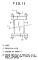
- a principal axis (C) is inclined from a loading direction (P), indicated by an arrow, by an angle in the range from 5 degrees to 25 degrees (see FIG. 11).
- Two principal axes are those which pass through the center of gravity (as same as the center of figure) of a section and are always perpendicular to each other, and, in any section, a moment of inertia is maximal about one of the axes, while a moment of inertia is minimal about the other of the axes.
- the angle referred to in the present invention is a smaller one of angles between the two principal axes and the loading direction.
- Conventional door beams of an aluminum alloy described in the Unexamined Japanese Patent Applications Nos. Hei 5-246242 and Hei 6-171362, and the like have a cross-section that as shown in FIG. 3, in a section perpendicular to a length direction, a compression-side flange 11 and a tension-side flange 12 are connected by a pair of webs 13, 14 and symmetric between the left and right sides.
- two principal axes are in parallel and perpendicular, respectively, to a loading direction and therefore, the angle said in present invention, the smaller angle between the principal axis and the loading direction, is 0 degree.
- a central line (a) of a compression-side flange is spaced from a central line (b) of a tension-side flange, under a bending load receives, as shown in FIG. 2, a beam section is apt to be flattened, producing buckling distortion (deformation into an almost rhombic shape).
- buckling distortion deformation into an almost rhombic shape.
- a principal axis (C) is inclined from a loading direction (P), indicated by an arrow, by an angle in the range from 5 degrees to 25 degrees.
- P loading direction
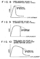
- the angle is less than 5 degrees, in a stage where a deformation is comparatively small, buckling distortion does not conspicuously appear (retains its original shape with ease), while as a tensile-strain in the tension-side flange is increased, rupture occurs as in the case of a conventional door beam.
- energy absorption is small (see FIG. 9).
- buckling distortion can be caused to occur in a stable manner in a stage where a deformation is comparatively large before rupture occurs, (see FIG. 10).
- a principal axis is inclined from a loading direction by an angle in the range from 5 degrees to 25 degrees, such as when a thickness each of the tension-side flange and the compression-side flange (or either of both) is not uniform and when neither the tension-side flange nor the compression-side is (or one of both is not) perpendicular to the webs geometrically and the like case, as shown in FIG. 12, the above described buckling distortion can be produced in a stable manner.
- Cross sectional parameters are intentionally devised so that in any case where a load is imposed, deformation about a principal axis about which a moment of inertia is minimal is easy to be produced but that the buckling distortion is produced in a stage where the deformation is as large as possible.
- a door beam according to the present invention is not limited to a door beam with a pair (two) of webs, but may be a door beam with one or three (or more than three) webs.
- a door beam according to the present invention is not limited to the case where lengths of extensions in both sides of the tension-side flange are different from each other and lengths of extensions in the both sides of the compression-side flange are also different from each other, but may include the case where lengths of extensions in both sides of one of the tension-side flange and the compression-side flange are different from each other, while lengths of extensions in the both sides of the other are same as each other.
- a section area of the tension-side flange is formed larger than that of the compression-side flange and thereby a neutral axis of bending is displaced toward the tension-side flange.
- a door beam of an Al-Zn-Mg series aluminum alloy has a Charpy impact value in the range from 23 to 34 J/cm 2 and an n value in the range from 0.05 to 0.17 and preferably a door beam of an Al-Si-Mg series aluminum alloy has a Charpy impact value in the range from 31 to 49 J/cm 2 and an n value in the range from 0.07 to 0.20.
- compositions of Al-Zn-Mg series aluminum alloys and Al-Si-Mg series aluminum alloys which are most preferably adopted will be described below.
- a preferable Al-Zn-Mg series aluminum alloy includes Zn and Mg in the ranges of Zn: 4 to 7 mass%, Mg: 0.8 to 1.5 mass%.
- other components can be included and a preferable Al-Zn-Mg series aluminum alloy comprises at least one kind in a content selected from the group consisting of the following elements in the content ranges of Zn: 4 to 7 mass%, Mg:0.8 to 1.5 mass%, Ti: 0.005 to 0.3 mass%, Cu: 0.05 to 0.6 mass%, Mn: 0.2 to 0.7 mass%, Cr: 0.05 to 0.3 mass% and Zr: 0.05 to 0.25 mass%, and the rest including aluminum and impurities.
- the reasons why the respective components in specified contents are added are as follows:
- Zn and Mg are necessary elements for maintaining a strength of an aluminum alloy.
- Zn is included at less than 4 mass% or Mg is included at less than 0.8 mass%, a desired strength cannot be attained.
- Zn is included at more than 7 mass% or Mg is included at more than 1.5 mass%, not only extrudability of an aluminum alloy is reduced, but elongation also decreases and desired characteristics cannot be obtained.
- the contents of Zn: 4 to 7 mass% and Mg: 0.8 to 1.5 mass% are selected.
- Ti is an element necessary for making a structure of ingot finer. When Ti is included at less than 0.05 mass%, an effect of the making finer is not sufficient, while when Ti is at more than 0.3 mass%, Ti is saturated to form a giant compound. Hence, a content of Ti: 0.05 to 0.3 mass% is selected.
- the elements raise a strength of an aluminum alloy.
- Cu is effective for improving on a resistance to a stress corrosion cracking of an aluminum alloy and Mn, Cr and Zr form a fiber structure in an extrusion and thereby strengthen the alloy, wherein one or two or more kinds selected from the elements are added in a proper manner.
- Preferable ranges of the metals are: Cu: 0.05 to 0.6 mass%, Mn: 0.2 to 0.7 mass%, Cr: 0.05 to 0.3 mass% and Zr: 0.05 to 0.25 mass%.
- Fe is an impurity most included in aluminum ground metal and when Fe is included in the alloy at more than 0.35 mass%, an intermetallic compound in the coarse form is formed being crystallized in casting, deteriorating mechanical properties. Hence, Fe is restricted at 0.35 mass% or less.
- impurities are incorporated through various routes such as a ground metal, an intermediate alloy of an additive metal and the like.
- Various elements are mixed into the aluminum alloy, but impurities other than Fe affect almost no influence on the characteristics of an aluminum alloy as far as respective contents of the impurities are singly 0.05 mass% or less and collectively 0.15 mass% or less. Therefore, the impurities are limited at 0.05 or less singly or 0.15 mass% or less collectively.
- a preferable Al-Si-Mg series aluminum alloy includes Si and Mg in the ranges of Si: 0.5 to 1.5mass%, Mg: 0.5 to 1.3 mass%.
- other components can be included and a preferable Al-Si-Mg series aluminum alloy comprises at least one kind in a content selected from the group consisting of the following elements in the content ranges of Si: 0.5 to 1.5 mass%, Mg:0.5 to 1.3 mass%, Ti: 0.005 to 0.2 mass%, Cu: 0.1 to 0.7 mass%, Mn: 0.05 to 0.6 mass%, Cr: 0.05 to 0.2 mass% and Zr: 0.05 to 0.2 mass%, and the rest including aluminum and impurities.
- the reasons why the respective components in specified contents are added are as follows:
- Si and Mg are necessary elements for maintaining a strength of an aluminum alloy.
- Si is included at less than 0.5 mass% or Mg is included at less than 0.5 mass% , a desired strength cannot be attained.
- Si is included at more than 1.5 mass% or Mg is included at more than 1.3 mass%, not only extrudability of an aluminum alloy is reduced, but elongation also decreases and desired characteristics cannot be obtained.
- the contents of Si : 0.5 to 1.5 mass% and Mg: 0.5 to 1.3 mass% are selected.
- a door beam series of the present invention is made of an extrusion of an aluminum alloy and a recrystallization thereof is preferably a fiber structure in order to attain a larger maximal load and a larger energy absorption, wherein a fiber structure is a structure, which is formed by extrusion, and which is observed in an extrusion and a micro-structure which is elongated along an extrusion direction.
- FIG. 1 shows a cross-section of a door beam according to the present invention.
- FIG. 2 is representation for illustrating progress in buckling distortion in cross-section of FIG. 1.
- FIG. 3 shows a cross-section of a conventional door beam.
- FIG. 4 is representation for illustrating a three-point bending test for a door beam.
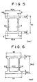
- FIG. 5 shows a cross-section of a door beam used in an example (the present invention).
- FIG. 6 shows a cross-section of a door beam used in an example (a comparative example).
- FIG. 7 is a load - displacement curve obtained in the examples.
- FIG. 8 shows a load-displacement curve when buckling occurs in a comparatively early stage.
- FIG. 9 shows a load-displacement curve when a rupture occurs in a comparatively early stage.
- FIG. 10 shows a load-displacement curve when buckling occurs in a comparatively late stage before a rupture occurs.
- FIG. 11 shows a basic cross-section of a door beam according to the present invention.
- FIG. 12 shows other types of cross-sections of door beams according to the present invention.
- unit weight maximal load rupture displacement buckling displacement Comparative example 0.98kg/m 1296kgf 129mm no occurrence Invention example 0.95(kg/m) 1306(kgf) no occurrence 132mm rupture displacement:a displacement of a semicircular cylinder rigid body when a tension-side flange is ruptured and a load is suddenly decreased.
- buckling displacement a displacement of a semicircular cylinder rigid body when a buckling distortion (deformation into an almost rhombic shape) conspicuously occurs and a load is suddenly decreased.
- a door beam of the comparative example had a rupture displacement of 129 mm, whereas the door beam of the present invention started buckling distortion at point (A) but rupture did not occur.
- a maximal load and an energy absorption (an area enveloped by a P- ⁇ curve) of the door beam according to the present invention were larger than the comparative example.
- an angle between a principal axis and a loading direction is preferably set at 25 degrees or less.
Landscapes
- Engineering & Computer Science (AREA)
- Mechanical Engineering (AREA)
- Body Structure For Vehicles (AREA)
- Vibration Dampers (AREA)
Applications Claiming Priority (2)
| Application Number | Priority Date | Filing Date | Title |
|---|---|---|---|
| JP10008098A JP3266099B2 (ja) | 1998-03-27 | 1998-03-27 | アルミニウム合金製ドアビーム |
| JP10008098 | 1998-03-27 |
Publications (3)
| Publication Number | Publication Date |
|---|---|
| EP0950553A2 true EP0950553A2 (fr) | 1999-10-20 |
| EP0950553A3 EP0950553A3 (fr) | 2001-07-11 |
| EP0950553B1 EP0950553B1 (fr) | 2005-06-08 |
Family
ID=14264475
Family Applications (1)
| Application Number | Title | Priority Date | Filing Date |
|---|---|---|---|
| EP99106316A Expired - Lifetime EP0950553B1 (fr) | 1998-03-27 | 1999-03-26 | Poutre de porte d'un alliage d'aluminium |
Country Status (6)
| Country | Link |
|---|---|
| US (1) | US6408591B1 (fr) |
| EP (1) | EP0950553B1 (fr) |
| JP (1) | JP3266099B2 (fr) |
| CA (1) | CA2266843C (fr) |
| DE (1) | DE69925667T2 (fr) |
| ES (1) | ES2244118T3 (fr) |
Cited By (2)
| Publication number | Priority date | Publication date | Assignee | Title |
|---|---|---|---|---|
| EP3489055B1 (fr) | 2017-11-22 | 2021-03-10 | Kabushiki Kaisha Kobe Seiko Sho (Kobe Steel, Ltd.) | Faisceau de porte |
| EP3572256B1 (fr) | 2018-04-24 | 2022-01-26 | Kabushiki Kaisha Kobe Seiko Sho (Kobe Steel, Ltd.) | Faisceau de porte |
Families Citing this family (16)
| Publication number | Priority date | Publication date | Assignee | Title |
|---|---|---|---|---|
| JP4693221B2 (ja) * | 2000-10-20 | 2011-06-01 | 株式会社神戸製鋼所 | アルミニウム合金製ドアビーム及びその製造方法 |
| US6722037B2 (en) * | 2001-12-06 | 2004-04-20 | Shape Corporation | Variable thickness tubular doorbeam |
| US7125067B2 (en) * | 2002-04-09 | 2006-10-24 | Ford Global Technologies, Llc | Magnesium door assembly for automobiles |
| US6826884B2 (en) * | 2002-08-19 | 2004-12-07 | Arunas Antanas Pabedinskas | Hollow flanged joist for deck framing |
| EP1510643B1 (fr) * | 2003-09-01 | 2017-12-13 | Forster Profilsysteme AG | Profilé et procédé de sa fabrication |
| JP4388340B2 (ja) * | 2003-10-03 | 2009-12-24 | 新日本製鐵株式会社 | 自動車用強度部材 |
| US7930866B2 (en) | 2004-08-02 | 2011-04-26 | Tac Technologies, Llc | Engineered structural members and methods for constructing same |
| US8266856B2 (en) | 2004-08-02 | 2012-09-18 | Tac Technologies, Llc | Reinforced structural member and frame structures |
| US8065848B2 (en) | 2007-09-18 | 2011-11-29 | Tac Technologies, Llc | Structural member |
| CA2575746C (fr) * | 2004-08-02 | 2011-03-01 | Tac Technologies, Llc | Organes structurels manufactures et leurs procedes de construction |
| US7721496B2 (en) | 2004-08-02 | 2010-05-25 | Tac Technologies, Llc | Composite decking material and methods associated with the same |
| US8177184B2 (en) | 2006-12-21 | 2012-05-15 | The Boeing Company | Seat track assembly |
| DE102009013241B4 (de) * | 2009-03-14 | 2011-01-20 | Weber, Ulrike, Dipl.-Ing. | Aus einem einstückigen Stahlbauprofil bestehender Träger |
| GB201114438D0 (en) * | 2011-08-22 | 2011-10-05 | Airbus Operations Ltd | A method of manufacturing an elongate component |
| JP7187120B2 (ja) * | 2019-05-22 | 2022-12-12 | 株式会社神戸製鋼所 | アルミニウム合金製ドアビーム |
| GB2592666A (en) * | 2020-03-06 | 2021-09-08 | Loadlok Mfg Limited | Decking beam |
Citations (4)
| Publication number | Priority date | Publication date | Assignee | Title |
|---|---|---|---|---|
| JPH05246242A (ja) | 1992-03-06 | 1993-09-24 | Kobe Steel Ltd | アルミニウム合金製自動車用補強部材 |
| JPH05319092A (ja) | 1992-05-20 | 1993-12-03 | Mazda Motor Corp | 自動車のドアインパクトバー構造 |
| JPH05330450A (ja) | 1992-05-29 | 1993-12-14 | Kobe Steel Ltd | インパクトビーム |
| JPH06171362A (ja) | 1992-12-04 | 1994-06-21 | Kobe Steel Ltd | アルミニウム合金製自動車用補強部材 |
Family Cites Families (27)
| Publication number | Priority date | Publication date | Assignee | Title |
|---|---|---|---|---|
| US496465A (en) * | 1893-05-02 | Structural iron form | ||
| US412397A (en) * | 1889-10-08 | Column | ||
| US496463A (en) * | 1893-05-02 | Structural iron form | ||
| US2444091A (en) * | 1944-07-25 | 1948-06-29 | Carlsen Olaf | Structural section and structural members composed thereof |
| US2583439A (en) * | 1946-07-20 | 1952-01-22 | Joseph H Oswald | Panel closure |
| DE1107945B (de) | 1958-03-08 | 1961-05-31 | Ver Deutsche Metallwerke Ag | Verwendung von AlZn Mg-Legierungen als Werkstoff fuer Schweisskonstruktionen |
| LU39019A1 (fr) * | 1959-08-25 | 1960-09-29 | ||
| US3332197A (en) * | 1964-06-30 | 1967-07-25 | James L Hinkle | Interlocked structural assemblies and stiffeners therefor |
| FR1534871A (fr) * | 1967-06-21 | 1968-08-02 | Profil Sa Ind Financ Le | Profilé en tôle formée à froid pour charpente |
| GB1173721A (en) * | 1968-05-06 | 1969-12-10 | Conder Internationale Ltd | Purlin |
| US3904380A (en) * | 1973-07-24 | 1975-09-09 | Marjorie Ann M Smith | Structural beam |
| GB1590435A (en) * | 1976-07-28 | 1981-06-03 | T I Metsec Ltd | Sleeve or lapped joints in purlin assemblies |
| GB1582426A (en) * | 1977-04-13 | 1981-01-07 | White Seal Design & Dev Ltd | Joining of panels |
| JPS58168913A (ja) | 1982-03-31 | 1983-10-05 | Toshiba Corp | 回転位置検出器 |
| JPS58168913U (ja) * | 1982-05-10 | 1983-11-11 | 日産自動車株式会社 | 車両用ドアの補強構造 |
| DE3606024A1 (de) | 1986-02-25 | 1987-08-27 | Aluminium Walzwerke Singen | Fahrzeugtuer mit aufprallprofil |
| DE3709489C1 (de) | 1987-03-25 | 1988-07-14 | Aluminium Walzwerke Singen | Aufpralltraeger fuer Fahrzeugtueren,insbesondere fuer Tueren von Personenkraftwagen |
| FR2656020B1 (fr) * | 1989-12-19 | 1995-04-14 | Profilcometube | Assemblage par emboitement de deux profiles a section droite en z, notamment pour la realisation d'une panne, d'une lisse ou d'un support de plancher. |
| US5056861A (en) * | 1990-04-23 | 1991-10-15 | Austria Metall Aktiengesellschaft | Impact girder for the side of an automotive vehicle |
| US5046777A (en) * | 1990-04-23 | 1991-09-10 | Austria Metall Aktiengesellschaft | Impact girder in an automobile wall assembly with intentional buckling of edge portions |
| JP2962036B2 (ja) * | 1992-04-16 | 1999-10-12 | 日産自動車株式会社 | 自動車のドア構造 |
| US6017403A (en) * | 1993-03-02 | 2000-01-25 | Yamaha Corporation | High strength and high rigidity aluminum-based alloy |
| FR2713664B1 (fr) | 1993-11-17 | 1996-05-24 | Pechiney Rhenalu | Alliage type Al-Si-Mg à ductilité et emboutissabilité améliorées et procédé d'obtention. |
| JP3068395B2 (ja) * | 1993-12-17 | 2000-07-24 | 株式会社神戸製鋼所 | アルミニウム合金製ドアインパクトビーム材 |
| US5551135A (en) * | 1994-05-25 | 1996-09-03 | Powers, Iii; John | Method of fabricating a metal purlin and method of fabricating a building therewith |
| DE19739595C1 (de) * | 1997-09-10 | 1999-02-04 | Daimler Benz Ag | Profil für einen Kipperboden |
| US6054197A (en) * | 1997-09-19 | 2000-04-25 | State University Of New York At Albany | Structural elements |
-
1998
- 1998-03-27 JP JP10008098A patent/JP3266099B2/ja not_active Expired - Lifetime
-
1999
- 1999-03-24 CA CA002266843A patent/CA2266843C/fr not_active Expired - Lifetime
- 1999-03-26 EP EP99106316A patent/EP0950553B1/fr not_active Expired - Lifetime
- 1999-03-26 ES ES99106316T patent/ES2244118T3/es not_active Expired - Lifetime
- 1999-03-26 US US09/277,224 patent/US6408591B1/en not_active Expired - Lifetime
- 1999-03-26 DE DE69925667T patent/DE69925667T2/de not_active Expired - Lifetime
Patent Citations (4)
| Publication number | Priority date | Publication date | Assignee | Title |
|---|---|---|---|---|
| JPH05246242A (ja) | 1992-03-06 | 1993-09-24 | Kobe Steel Ltd | アルミニウム合金製自動車用補強部材 |
| JPH05319092A (ja) | 1992-05-20 | 1993-12-03 | Mazda Motor Corp | 自動車のドアインパクトバー構造 |
| JPH05330450A (ja) | 1992-05-29 | 1993-12-14 | Kobe Steel Ltd | インパクトビーム |
| JPH06171362A (ja) | 1992-12-04 | 1994-06-21 | Kobe Steel Ltd | アルミニウム合金製自動車用補強部材 |
Cited By (2)
| Publication number | Priority date | Publication date | Assignee | Title |
|---|---|---|---|---|
| EP3489055B1 (fr) | 2017-11-22 | 2021-03-10 | Kabushiki Kaisha Kobe Seiko Sho (Kobe Steel, Ltd.) | Faisceau de porte |
| EP3572256B1 (fr) | 2018-04-24 | 2022-01-26 | Kabushiki Kaisha Kobe Seiko Sho (Kobe Steel, Ltd.) | Faisceau de porte |
Also Published As
| Publication number | Publication date |
|---|---|
| US6408591B1 (en) | 2002-06-25 |
| JP3266099B2 (ja) | 2002-03-18 |
| CA2266843C (fr) | 2003-06-10 |
| DE69925667D1 (de) | 2005-07-14 |
| EP0950553A3 (fr) | 2001-07-11 |
| DE69925667T2 (de) | 2006-03-23 |
| EP0950553B1 (fr) | 2005-06-08 |
| ES2244118T3 (es) | 2005-12-01 |
| CA2266843A1 (fr) | 1999-09-27 |
| JPH11278054A (ja) | 1999-10-12 |
Similar Documents
| Publication | Publication Date | Title |
|---|---|---|
| EP0950553B1 (fr) | Poutre de porte d'un alliage d'aluminium | |
| US7665586B2 (en) | Crash box | |
| US6908141B2 (en) | Structural member for car and car body fabricated using the member | |
| KR102575797B1 (ko) | 내소성변형성이 가변하는 횡방향 빔을 포함하는 차량 언더보디 구조물 | |
| KR100619295B1 (ko) | 자동차용 강도 부재 | |
| EP3464033B1 (fr) | Élément longitudinal pour véhicule poids lourd | |
| JPH0463242A (ja) | 車体補強用鋼管 | |
| US6338817B2 (en) | Aluminum extruded door beam material | |
| JP3967926B2 (ja) | 自動車用ドアインパクトビーム | |
| US20100180990A1 (en) | Impact beam comprising precipitation hardenable stainless steel | |
| JP2908929B2 (ja) | アルミニウム合金製自動車衝撃吸収部材 | |
| JP3668794B2 (ja) | アルミニウム合金製ドアビーム材 | |
| JPH05311309A (ja) | アルミニウム合金製自動車サイドドアインパクトビーム | |
| JP2939243B2 (ja) | アルミニウム製ドアビーム材 | |
| JP4090471B2 (ja) | アルミニウム合金製ドアビーム材の取付構造 | |
| JPH11314521A (ja) | アルミニウム製ドアビ―ム材 | |
| JP4773853B2 (ja) | 自動車ドアビーム用アルミニウム合金押出形材 | |
| JP2007245987A5 (fr) | ||
| JP4143015B2 (ja) | 自動車用補強部材 | |
| JPH0691325A (ja) | 自動車ドア補強材用鋼管 | |
| JPH1136039A (ja) | 動的変形特性に優れた高強度鋼板 |
Legal Events
| Date | Code | Title | Description |
|---|---|---|---|
| PUAI | Public reference made under article 153(3) epc to a published international application that has entered the european phase |
Free format text: ORIGINAL CODE: 0009012 |
|
| 17P | Request for examination filed |
Effective date: 19990422 |
|
| AK | Designated contracting states |
Kind code of ref document: A2 Designated state(s): DE ES FR GB NL |
|
| AX | Request for extension of the european patent |
Free format text: AL;LT;LV;MK;RO;SI |
|
| PUAL | Search report despatched |
Free format text: ORIGINAL CODE: 0009013 |
|
| AK | Designated contracting states |
Kind code of ref document: A3 Designated state(s): AT BE CH CY DE DK ES FI FR GB GR IE IT LI LU MC NL PT SE |
|
| AX | Request for extension of the european patent |
Free format text: AL;LT;LV;MK;RO;SI |
|
| AKX | Designation fees paid |
Free format text: DE ES FR GB NL |
|
| 17Q | First examination report despatched |
Effective date: 20030610 |
|
| GRAP | Despatch of communication of intention to grant a patent |
Free format text: ORIGINAL CODE: EPIDOSNIGR1 |
|
| GRAA | (expected) grant |
Free format text: ORIGINAL CODE: 0009210 |
|
| GRAS | Grant fee paid |
Free format text: ORIGINAL CODE: EPIDOSNIGR3 |
|
| AK | Designated contracting states |
Kind code of ref document: B1 Designated state(s): DE ES FR GB NL |
|
| REG | Reference to a national code |
Ref country code: GB Ref legal event code: FG4D |
|
| REF | Corresponds to: |
Ref document number: 69925667 Country of ref document: DE Date of ref document: 20050714 Kind code of ref document: P |
|
| PLBI | Opposition filed |
Free format text: ORIGINAL CODE: 0009260 |
|
| REG | Reference to a national code |
Ref country code: ES Ref legal event code: FG2A Ref document number: 2244118 Country of ref document: ES Kind code of ref document: T3 |
|
| 26 | Opposition filed |
Opponent name: ALCAN TECHNOLOGY & MANAGEMENT AG Effective date: 20051110 |
|
| ET | Fr: translation filed | ||
| NLR1 | Nl: opposition has been filed with the epo |
Opponent name: ALCAN TECHNOLOGY & MANAGEMENT AG |
|
| PLAX | Notice of opposition and request to file observation + time limit sent |
Free format text: ORIGINAL CODE: EPIDOSNOBS2 |
|
| PLBB | Reply of patent proprietor to notice(s) of opposition received |
Free format text: ORIGINAL CODE: EPIDOSNOBS3 |
|
| PLAY | Examination report in opposition despatched + time limit |
Free format text: ORIGINAL CODE: EPIDOSNORE2 |
|
| PLBC | Reply to examination report in opposition received |
Free format text: ORIGINAL CODE: EPIDOSNORE3 |
|
| PLAB | Opposition data, opponent's data or that of the opponent's representative modified |
Free format text: ORIGINAL CODE: 0009299OPPO |
|
| R26 | Opposition filed (corrected) |
Opponent name: ALCAN TECHNOLOGY & MANAGEMENT AG Effective date: 20051110 |
|
| PLCK | Communication despatched that opposition was rejected |
Free format text: ORIGINAL CODE: EPIDOSNREJ1 |
|
| NLR1 | Nl: opposition has been filed with the epo |
Opponent name: ALCAN TECHNOLOGY & MANAGEMENT AG |
|
| APBP | Date of receipt of notice of appeal recorded |
Free format text: ORIGINAL CODE: EPIDOSNNOA2O |
|
| APAH | Appeal reference modified |
Free format text: ORIGINAL CODE: EPIDOSCREFNO |
|
| APBU | Appeal procedure closed |
Free format text: ORIGINAL CODE: EPIDOSNNOA9O |
|
| PLBN | Opposition rejected |
Free format text: ORIGINAL CODE: 0009273 |
|
| STAA | Information on the status of an ep patent application or granted ep patent |
Free format text: STATUS: OPPOSITION REJECTED |
|
| 27O | Opposition rejected |
Effective date: 20080809 |
|
| NLR2 | Nl: decision of opposition |
Effective date: 20080809 |
|
| REG | Reference to a national code |
Ref country code: FR Ref legal event code: PLFP Year of fee payment: 18 |
|
| REG | Reference to a national code |
Ref country code: FR Ref legal event code: PLFP Year of fee payment: 19 |
|
| REG | Reference to a national code |
Ref country code: FR Ref legal event code: PLFP Year of fee payment: 20 |
|
| PGFP | Annual fee paid to national office [announced via postgrant information from national office to epo] |
Ref country code: DE Payment date: 20180313 Year of fee payment: 20 Ref country code: GB Payment date: 20180321 Year of fee payment: 20 Ref country code: NL Payment date: 20180314 Year of fee payment: 20 |
|
| PGFP | Annual fee paid to national office [announced via postgrant information from national office to epo] |
Ref country code: FR Payment date: 20180223 Year of fee payment: 20 |
|
| PGFP | Annual fee paid to national office [announced via postgrant information from national office to epo] |
Ref country code: ES Payment date: 20180402 Year of fee payment: 20 |
|
| REG | Reference to a national code |
Ref country code: DE Ref legal event code: R071 Ref document number: 69925667 Country of ref document: DE |
|
| REG | Reference to a national code |
Ref country code: NL Ref legal event code: MK Effective date: 20190325 |
|
| REG | Reference to a national code |
Ref country code: GB Ref legal event code: PE20 Expiry date: 20190325 |
|
| PG25 | Lapsed in a contracting state [announced via postgrant information from national office to epo] |
Ref country code: GB Free format text: LAPSE BECAUSE OF EXPIRATION OF PROTECTION Effective date: 20190325 |
|
| REG | Reference to a national code |
Ref country code: ES Ref legal event code: FD2A Effective date: 20200806 |
|
| PG25 | Lapsed in a contracting state [announced via postgrant information from national office to epo] |
Ref country code: ES Free format text: LAPSE BECAUSE OF EXPIRATION OF PROTECTION Effective date: 20190327 |