EP0950736A2 - Broche - Google Patents
Broche Download PDFInfo
- Publication number
- EP0950736A2 EP0950736A2 EP99107135A EP99107135A EP0950736A2 EP 0950736 A2 EP0950736 A2 EP 0950736A2 EP 99107135 A EP99107135 A EP 99107135A EP 99107135 A EP99107135 A EP 99107135A EP 0950736 A2 EP0950736 A2 EP 0950736A2
- Authority
- EP
- European Patent Office
- Prior art keywords
- spindle
- bobbin
- coupling
- spindle according
- pot
- Prior art date
- Legal status (The legal status is an assumption and is not a legal conclusion. Google has not performed a legal analysis and makes no representation as to the accuracy of the status listed.)
- Withdrawn
Links
Images


Classifications
-
- D—TEXTILES; PAPER
- D01—NATURAL OR MAN-MADE THREADS OR FIBRES; SPINNING
- D01H—SPINNING OR TWISTING
- D01H7/00—Spinning or twisting arrangements
- D01H7/02—Spinning or twisting arrangements for imparting permanent twist
- D01H7/88—Hollow-spindle arrangements
-
- D—TEXTILES; PAPER
- D01—NATURAL OR MAN-MADE THREADS OR FIBRES; SPINNING
- D01H—SPINNING OR TWISTING
- D01H1/00—Spinning or twisting machines in which the product is wound-up continuously
- D01H1/10—Spinning or twisting machines in which the product is wound-up continuously for imparting multiple twist, e.g. two-for-one twisting
- D01H1/105—Arrangements using hollow spindles, i.e. the yarns are running through the spindle of the unwound bobbins
-
- D—TEXTILES; PAPER
- D01—NATURAL OR MAN-MADE THREADS OR FIBRES; SPINNING
- D01H—SPINNING OR TWISTING
- D01H7/00—Spinning or twisting arrangements
- D01H7/02—Spinning or twisting arrangements for imparting permanent twist
- D01H7/86—Multiple-twist arrangements, e.g. two-for-one twisting devices ; Threading of yarn; Devices in hollow spindles for imparting false twist
Definitions
- the invention relates to a spindle according to the preamble of patent claim 1.
- the invention has for its object to design the spindle so that it either as a twisting spindle, in particular a multi-wire twisting spindle in the form of a Double-wire twist spindle or a triple-wire twist spindle, or as a specialist or Spool spindle can be used.
- the spindle according to the invention is characterized by a movable up and down movable installation member in the bobbin Laying in particular e.g. specialist thread drawn from a creel on the spool rotating with the driven bobbin.
- the bobbin will be in the usual way, for example by means of a magnetic coupling that can be switched on or off secured against rotation.
- the bobbin and the twister are preferably rotated in opposite directions.
- the drive of the twister is stopped.
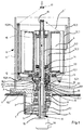
- FIG. 1 shows a section of a machine frame 1 with a drive and bearing housing 2 and bearing housing cover 3 for storing a double wire twisting spindle S.
- the bearing housing 2 is an electric motor consisting of stator 4 and rotor 5 to drive a hollow shaft 6 housed in its lower section 6.1 the function of the usual spindle shaft and in its upper section 6.2 the Has the function of the spindle hollow axis customary in a double-wire twisting spindle.
- the spindle shaft section 6.1 of the hollow shaft 6 is not part of the invention Way stored in a bearing hub of the bearing housing cover 3 by means of bearings 7 and 8.
- the twist pot 10 consisting of bearing hub 10.1, Thread pot bottom 10.2 and thread pot jacket 10.3, which is supported by a spindle housing 11 is surrounded.
- a coil support 12 consisting of coil support base 12.1, coil support hub 12.2 and coil carrier protection pot 12.3, on the one hand, with its coil carrier base 12.1 with the interposition of an axial bearing 13 on the top of the bottom of the twister 10.2 and on the other hand by means of its coil carrier hub 12.2 on the upper one Section of the hollow shaft 6 forming spindle hollow axis 6.2 mounted.
- the thread inlet tube 16 is plugged into the axial extension, the centering eyelet 17 customary for a double-wire twisting spindle lies.
- the spindle hollow axis 6.2 is in the region of its lower end with a radial opening 6.21 provided, the a radially through the Zwirntopfêt 10.2 thread guide channel 10.21 is opposite, to which one in the axial direction through the twist pot jacket 10.3 guided thread guide channel 10.31 connects.
- the coupling piece 21 is preferably conical Coupling surface against a mating coupling surface in the bearing bush 10.1 of the Zwimtopfes, the pressure force between the coupling piece and bearing bush 10.1 supported by a compression spring 22 supported on the bearing 14 or increased, which bears against the top of the coupling piece.
- the lifting rod 19 is in a lower position.
- the flight position between the radial opening 6.21 of the spindle hollow axis, the radial opening 21.2 of the coupling piece and the thread guide channel 10.21 of the twisting pot is replaced by a locking element 23 ensured.
- On the bobbin 12 is a coil to be wound, in the present case one Disc spool D, attached.
- a laying head 24 is shown above the spindle housing 11, with which, for example, by means of a pinion drive 25, a laying pipe 26 can be inserted into the coil support protective pot 12.3 on the one hand and can be moved up and down in the direction of the arrows f2, f3 in order to rotate while rotating Thread bobbin D to lay a thread b drawn from bobbin feed spools V, see FIG. 4, on the bobbin.
- the invention thus makes it possible to use e.g. in a first Work cycle to wind up a special coil and then in a second work cycle in the manner shown in Figure 1, this thread from the supply spool A subtract and twist according to the double wire principle and one Wind up spool C.
- the embodiment according to FIG. 3 differs from the embodiment according to Figures 1 and 2 characterized in that the coupling through a along the hollow shaft 6 slidable coupling sliding sleeve 31 is formed on her Has outer teeth 31.3.
- the twist pot hub 10.1 is with a Provide the internal toothing 10.11 interacting with the external toothing 31.3.
- the coil carrier hub 12.2 is also provided with an external toothing 31.3 Sliding sleeve 31 cooperating internal teeth 12.21.
- Figure 5 shows a bearing and driven housing 31 with a bottom 31.1 and one central bearing hub connected to the floor 31.2. On the top of the case 31 there is a housing cover 32 which has a further bearing hub 32.1 having.
- a spindle shadow 35 can be rotated in the bearing hub 31.2 by means of bearings 33 and 34 stored, at the lower end of a rotatable in the direction of arrow 11
- Spindelwirel 36 is attached.
- the spindle shaft carries at its upper end the twist pot 37, through the bottom 37.1 of which a radial thread guide channel is provided 37.2 leads.
- At the inner end of the thread guide channel 37.2 closes in the extension of the spindle shaft 35 lying on the hollow spindle axis 37.3, which according to FIG can be formed, for example, in one piece with the twist pot 37.
- a coil carrier 40 containing a coil carrier protection pot 40.1 and a coil carrier base 40.2 is with a coil carrier hub attached to the coil carrier base 40.2 40.3 by means of bearings 38 and 39 rotatable on the hollow spindle axis 37.3 stored.
- the bobbin 40 is used for receiving or storing a compartment or supply bobbin D, which is placed with its coil sleeve on the coil carrier base 40.2.
- a sleeve 43 is rotatably mounted in the bearing hub 32.1 by means of bearings 41 and 42, the one at its lower end preferably opposite the spindle whorl 36 drivable whorls 44 and at its upper end carries a flange 45 into which Driver magnets 48 extending along a circular path are used.
- This one Magnets 48 are located in the coil carrier base 40.2 counter magnets 49 opposite, which, based on the driving magnets 48, are polarized such that with the whirl 44 rotating, the coil carrier 40 is also set in rotation.
- the thread F is lifted up from the supply spool withdrawn and into the spindle hollow axis 37.3 first down and then through the Thread guide channel 37.2 radially outwards and then again along the twist-pot shell 37.4 up to one lying in the extension of the hollow spindle axis Thread guide eyelet 43 guided from where the thread to a not shown Rewinder is running.
- the twist pot jacket 37.4 is at its upper end a thread guide eyelet 37.5 stabilizing the thread guide.
- the whorl 44 is opposed to the spindle whorl 36 set in rotation, whereby the coil carrier 40 and thus the supply spool D are also set in rotation, whereby for the the thread guide eyelet 50 stripped triple twist becomes.
- the coil inserted into the coil carrier according to FIG. 6 is a winding coil D to be wound on which with the twister 37 at rest and rotating Coil carrier 40, for example, from a creel, not shown pulled thread b by means of the up and down movable laying pipe 26 is relocated.
- the invention thus makes it possible to use e.g. in one winding a technical coil in the first step and then in a second Operation in the manner shown in Figure 6, this thread from the specialist or Subtract supply spool D and according to the triple wire principle twist and wind up in the usual way to a twine spool.
Landscapes
- Engineering & Computer Science (AREA)
- Mechanical Engineering (AREA)
- Textile Engineering (AREA)
- Spinning Or Twisting Of Yarns (AREA)
- Guides For Winding Or Rewinding, Or Guides For Filamentary Materials (AREA)
Applications Claiming Priority (4)
| Application Number | Priority Date | Filing Date | Title |
|---|---|---|---|
| DE1998117315 DE19817315C1 (de) | 1998-04-18 | 1998-04-18 | Spindel |
| DE1998117314 DE19817314C2 (de) | 1998-04-18 | 1998-04-18 | Spindel, insbesondere Dreifachdraht-Zwirnspindel |
| DE19817314 | 1998-04-18 | ||
| DE19817315 | 1998-04-18 |
Publications (2)
| Publication Number | Publication Date |
|---|---|
| EP0950736A2 true EP0950736A2 (fr) | 1999-10-20 |
| EP0950736A3 EP0950736A3 (fr) | 2001-01-17 |
Family
ID=26045593
Family Applications (1)
| Application Number | Title | Priority Date | Filing Date |
|---|---|---|---|
| EP99107135A Withdrawn EP0950736A3 (fr) | 1998-04-18 | 1999-04-13 | Broche |
Country Status (5)
| Country | Link |
|---|---|
| US (1) | US6244028B1 (fr) |
| EP (1) | EP0950736A3 (fr) |
| JP (1) | JPH11315431A (fr) |
| CN (1) | CN1234458A (fr) |
| CZ (1) | CZ136499A3 (fr) |
Families Citing this family (10)
| Publication number | Priority date | Publication date | Assignee | Title |
|---|---|---|---|---|
| KR100481938B1 (ko) * | 2002-06-20 | 2005-04-13 | 한국기계연구원 | 복합사 연사장치 |
| NL1024504C2 (nl) * | 2003-10-10 | 2005-04-12 | Ten Cate Thiolon Bv | Inrichting voor het opwikkelen van een langgerekt, draadvormig lichaam op een wikkellichaam. |
| KR100689601B1 (ko) | 2006-10-21 | 2007-03-08 | 김용훈 | 삼중 연사장치 |
| JP2012001857A (ja) * | 2010-06-18 | 2012-01-05 | Murata Mach Ltd | 合撚糸機、および合撚糸機を使った合撚糸の製造方法 |
| CN101935899B (zh) * | 2010-06-25 | 2012-01-04 | 张朝山 | 带有下进纱通道的捻纱锭子 |
| CN102618979B (zh) * | 2011-01-28 | 2014-09-10 | 武汉纺织大学 | 一种具有在线加热加湿的柔顺倍捻锭子 |
| RU2538521C1 (ru) * | 2013-07-04 | 2015-01-10 | Общество с ограниченной ответственностью ХОЗРАСЧЕТНЫЙ ТВОРЧЕСКИЙ ЦЕНТР УФИМСКОГО АВИАЦИОННОГО ИНСТИТУТА | Способ оценки эффективности смазочно-охлаждающих жидкостей при шлифовании |
| CN103806147B (zh) * | 2014-02-28 | 2016-10-05 | 浙江日发纺织机械股份有限公司 | 一转四捻股纱加捻锭子 |
| CN106087144B (zh) * | 2016-07-29 | 2018-07-24 | 浙江天竺纺机有限公司 | 一种纱线的加捻装置 |
| CN107099894B (zh) * | 2017-06-23 | 2023-06-23 | 新昌县城南东明轴承厂 | 一种三倍捻纺锭及纺机 |
Family Cites Families (8)
| Publication number | Priority date | Publication date | Assignee | Title |
|---|---|---|---|---|
| US2537506A (en) * | 1947-01-22 | 1951-01-09 | Beria Antonio | Winding spindle |
| CH322204A (de) * | 1954-11-22 | 1957-06-15 | Spinnerei Karl Marx Veb | Fadenabwickelvorrichtung an Doppeldrahtspindeln |
| US2788632A (en) * | 1956-01-13 | 1957-04-16 | Haskell Dawes Machine Company | Tension control in twisting machines and the like |
| DE1292555B (de) * | 1966-03-02 | 1969-04-10 | Palitex Project Co Gmbh | Doppeldrahtzwirnspindel mit innenliegender Aufwickelspule |
| US3406511A (en) * | 1967-07-27 | 1968-10-22 | Palitex Project Co Gmbh | Two-for-one twisting spindle with interior winding-up of the thread |
| DE2404934C2 (de) * | 1974-02-01 | 1983-09-22 | Kievskie eksperimental'nye masterskie, Kiev | Einprozeß-Zwirnmaschine zur Erzeugung von Zwirn aus zwei Strängen |
| DE4010019A1 (de) * | 1990-03-29 | 1991-10-02 | Palitex Project Co Gmbh | Spindel zum herstellen eines fadens |
| FR2663048B1 (fr) * | 1990-06-06 | 1992-09-18 | Ishikawa Seisakusho Kk | Appareil a broche a double torsion. |
-
1999
- 1999-04-08 JP JP11101027A patent/JPH11315431A/ja active Pending
- 1999-04-13 EP EP99107135A patent/EP0950736A3/fr not_active Withdrawn
- 1999-04-16 US US09/292,926 patent/US6244028B1/en not_active Expired - Fee Related
- 1999-04-16 CZ CZ991364A patent/CZ136499A3/cs unknown
- 1999-04-17 CN CN99107223A patent/CN1234458A/zh active Pending
Also Published As
| Publication number | Publication date |
|---|---|
| US6244028B1 (en) | 2001-06-12 |
| CN1234458A (zh) | 1999-11-10 |
| CZ136499A3 (cs) | 1999-11-17 |
| JPH11315431A (ja) | 1999-11-16 |
| EP0950736A3 (fr) | 2001-01-17 |
Similar Documents
| Publication | Publication Date | Title |
|---|---|---|
| EP0950736A2 (fr) | Broche | |
| DE1510976A1 (de) | Ablaufhilfe fuer das Abziehen von Faeden ueber Kopf von Spulen aller Art | |
| DE102016006148A1 (de) | Aufspulmaschine | |
| DE3009275C2 (de) | Vorrichtung zum Anheben einer auf eine Spindel einer Textilmaschine, insbesondere einer Umwindespinnmaschine, aufgesteckten Spule | |
| EP2157217B1 (fr) | Dispositif de serrage | |
| WO1998011284A1 (fr) | Continu a filer a pots tournants | |
| EP1488028A1 (fr) | Dispositif de filage centrifuge | |
| DE19817315C1 (de) | Spindel | |
| DE1923855A1 (de) | Verbesserung an Textilgarnverarbeitungsmaschinen | |
| EP0458088B1 (fr) | Dispositif de sectionnement pour une broche d'un métier à filer ou à retordre | |
| DE3310438A1 (de) | In ihrer geometrischen form veraenderbare ablaufhilfe fuer den ueberkopf-abzug eines fadens von einer vorlagespule | |
| DE2544689C3 (de) | Spindel für Ringspinn- und Ringzwirnmaschinen, insbesondere für Cordzwirnmaschinen | |
| EP3257979B1 (fr) | Dispositif pince-fil | |
| DE19817314C2 (de) | Spindel, insbesondere Dreifachdraht-Zwirnspindel | |
| DE10151167A1 (de) | Verfahren und Vorrichtung zum Kablieren oder Verzwirnen von mindestens zwei Fäden sowie Kablier- und/oder Doppeldrahtzwirn-Spindel zur Durchführung dieses Verfahrens | |
| EP0319784B1 (fr) | Procédé pour le changement automatique de bobines pour les machines de filature | |
| EP0887446A2 (fr) | Procédé et broche de retordage d'un fil triple pour assemblage et retordage simultanés | |
| DE2038654C3 (de) | An einer Spinnspindel befestigter Konus für Abfallgarn | |
| EP1028181B1 (fr) | Métier a filer centrifuge et procédé de filage centrifuge | |
| DE69120519T2 (de) | Verfahren zum kontinuierlichen Spinne von Stapelfasern und Vorrichtung zur Durchführ des Verfahrens | |
| DE2142637A1 (de) | Abfallgarnspule | |
| EP0915193B1 (fr) | Broche à double torsion | |
| DE3909673A1 (de) | Spinnmaschine | |
| DE102006008339A1 (de) | Aufspulmaschine | |
| DE1910929C (de) | Vorrichtung zum Einsetzen von Ablaufspulen in Doppeldrahtzwirnspindeln |
Legal Events
| Date | Code | Title | Description |
|---|---|---|---|
| PUAI | Public reference made under article 153(3) epc to a published international application that has entered the european phase |
Free format text: ORIGINAL CODE: 0009012 |
|
| AK | Designated contracting states |
Kind code of ref document: A2 Designated state(s): CH DE FR GB IT LI |
|
| AX | Request for extension of the european patent |
Free format text: AL;LT;LV;MK;RO;SI |
|
| PUAL | Search report despatched |
Free format text: ORIGINAL CODE: 0009013 |
|
| AK | Designated contracting states |
Kind code of ref document: A3 Designated state(s): AT BE CH CY DE DK ES FI FR GB GR IE IT LI LU MC NL PT SE |
|
| AX | Request for extension of the european patent |
Free format text: AL;LT;LV;MK;RO;SI |
|
| 17P | Request for examination filed |
Effective date: 20010710 |
|
| AKX | Designation fees paid |
Free format text: CH DE FR GB IT LI |
|
| STAA | Information on the status of an ep patent application or granted ep patent |
Free format text: STATUS: THE APPLICATION HAS BEEN WITHDRAWN |
|
| 18W | Application withdrawn |
Withdrawal date: 20020606 |