EP0950754A1 - Siebvorrichtung - Google Patents
Siebvorrichtung Download PDFInfo
- Publication number
- EP0950754A1 EP0950754A1 EP98120156A EP98120156A EP0950754A1 EP 0950754 A1 EP0950754 A1 EP 0950754A1 EP 98120156 A EP98120156 A EP 98120156A EP 98120156 A EP98120156 A EP 98120156A EP 0950754 A1 EP0950754 A1 EP 0950754A1
- Authority
- EP
- European Patent Office
- Prior art keywords
- tank
- screen
- papermaking material
- supply inlet
- foreign substance
- Prior art date
- Legal status (The legal status is an assumption and is not a legal conclusion. Google has not performed a legal analysis and makes no representation as to the accuracy of the status listed.)
- Granted
Links
- 239000000463 material Substances 0.000 claims abstract description 114
- 239000000126 substance Substances 0.000 claims abstract description 82
- 238000003756 stirring Methods 0.000 claims abstract description 16
- 230000003247 decreasing effect Effects 0.000 claims description 7
- 238000007599 discharging Methods 0.000 abstract description 4
- 239000000835 fiber Substances 0.000 description 15
- 230000000694 effects Effects 0.000 description 9
- 238000012216 screening Methods 0.000 description 8
- 238000009833 condensation Methods 0.000 description 7
- 230000005494 condensation Effects 0.000 description 7
- 238000013459 approach Methods 0.000 description 4
- 239000004033 plastic Substances 0.000 description 2
- 229920003023 plastic Polymers 0.000 description 2
- 238000000926 separation method Methods 0.000 description 2
- 238000004140 cleaning Methods 0.000 description 1
- 238000000034 method Methods 0.000 description 1
- 239000010899 old newspaper Substances 0.000 description 1
- 239000000123 paper Substances 0.000 description 1
- 230000008719 thickening Effects 0.000 description 1
Images





Classifications
-
- D—TEXTILES; PAPER
- D21—PAPER-MAKING; PRODUCTION OF CELLULOSE
- D21D—TREATMENT OF THE MATERIALS BEFORE PASSING TO THE PAPER-MAKING MACHINE
- D21D5/00—Purification of the pulp suspension by mechanical means; Apparatus therefor
- D21D5/02—Straining or screening the pulp
- D21D5/023—Stationary screen-drums
- D21D5/026—Stationary screen-drums with rotating cleaning foils
Definitions
- the present invention relates to a screen apparatus, and more particularly, to a screen apparatus which can improve a processing amount and an effect of separating good fibers and foreign substances.
- a papermaking material received in a tank is stirred by a stirring member, and foreign substances in the papermaking material is removed through a screen to thereby screen or select the papermaking material.
- the papermaking material is condensed.
- An object of the invention is to provide a screen apparatus which can obviate the aforementioned problems.
- the present invention provides a screen apparatus including a tank for receiving a papermaking material; a screen for dividing the tank into a first chamber and a second chamber and separating a foreign substance from the papermaking material; a first supply passage for supplying the papermaking material into the tank and including a first supply inlet located at an upper side of the tank; a second supply passage for supplying the papermaking material into the tank and including a second supply inlet located lower than the first supply inlet; a stirring member disposed between an inner wall of the tank and the screen and stirring the papermaking material in the first chamber; a screened papermaking material discharge passage communicating with the second chamber and leading the papermaking material screened by the screen to an outside of the tank; and a foreign substance discharge passage communicating with the first chamber and leading the foreign substance, which does not pass through the screen, to the outside of the tank.
- the first supply inlet may be located higher than the openings provided at an uppermost part of the screen.
- the second supply inlet may be located lower than the openings provided at a lowermost part of the screen. Since the first and second supply inlets are not opposed to the openings of the screen, the screen is not damaged by the papermaking material with the foreign substance ejecting thereto.
- a foreign substance discharge outlet of the foreign substance discharge passage may be located between the first supply inlet and the second supply inlet.
- an upper projecting member may be disposed circularly above the foreign substance discharge outlet to project from an inner wall of the tank, and a lower projecting member may be disposed circularly below the foreign substance discharge outlet to project from the inner wall of the tank.
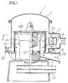
- numeral 1 designates a screen apparatus
- the screen apparatus 1 is an apparatus for screening or removing foreign substances, such as plastic, from a papermaking material, i.e. old newspaper, old cardboard paper, or the like.
- the screen apparatus 1 is a so-called inward type screen apparatus (centripetal type in which a stirring member 10 rotates outside a screen 3 described later), wherein the papermaking material flows from an outside of the screen toward an inside thereof to be screened.
- the screen apparatus 1 includes a tank 2 for receiving the papermaking material.
- the tank 2 is divided into a first chamber 4 and a second chamber 5 by the screen 3 for separating foreign substances contained in the papermaking material.
- the screen 3 has, for example, a substantially cylindrical shape, wherein an upper surface thereof is closed and a lower surface thereof is opened, and includes openings 3a in the shape of a round hole or slit on the side surface thereof.
- the screen 3 is supported by a support cylinder 100 with a bearing.
- Numeral 7 designates a first supply passage.
- the first supply passage 7 supplies the papermaking material to the tank 2, and includes a first supply inlet 7a located at an upper side of the tank 2.
- Numeral 8 designates a second supply passage.
- the second supply passage 8 supplies the papermaking material to the tank 2, and includes a second supply inlet 8a located lower than the first supply inlet 7a in the tank 2.
- first supply passage 7 and the second supply passage 8 for example, a papermaking material with a concentration of approximately 1 % is supplied into the tank 2.
- the first supply passage 7 and the second supply passage 8 are branched from a supply passage P.
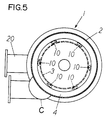
- the stirring member 10 is provided between an inner wall of the tank 2 and the screen 3.
- the stirring member 10 stirs the papermaking material in the first chamber 4, and at the same time, applies a positive pressure against the screen 3 in a front part of the stirring member 10, and a negative pressure against the screen 3 in a rear part of the stirring member 10, so that the stirring member 10 performs a screen cleaning operation for removing papermaking materials clogged in the screen 3.
- the stirring member 10 is rotated by a motor, not shown, through belts 11 and a rotary shaft 12.
- Numeral 20 designates a screened papermaking material discharge passage.
- the screened papermaking material discharge passage 20 communicates with the second chamber 5, and leads the papermaking material screened by the screen 3 to the outside of the tank 2.
- Numeral 30 designates a foreign substance discharge passage.
- the foreign substance discharge passage 30 communicates with the first chamber 4, and leads the foreign substances contained in the papermaking material, which do not pass through the screen 3, to the outside of the tank 2.
- the papermaking material is supplied to the tank 2 through the first supply passage 7 and the second supply passage 8, and the papermaking material in the first chamber 4 is stirred by the stirring member 10.
- Foreign substances, such as plastics, contained in the papermaking material can not pass through the screen 3, and are stored in the first chamber 4.
- the papermaking material which passes through the screen 3 is led to the outside of the tank 2 through the screened papermaking material discharge passage 20.
- an open degree of a valve, not shown, which opens and closes the foreign substance discharge passage 30, is adjusted such that the valve is opened continuously, or the valve is intermittently opened and closed, to thereby lead the foreign substances, which can not pass through the screen 3, to the outside of the tank 2 through the foreign substance discharge passage 30.
- the papermaking material As it approaches the lower part of the tank 2, that is, as the flow of the papermaking material approaches the downstream side, the papermaking material is condensed or thickened, so that the material passing resistance through the screen due to the condensation of the papermaking material is increased to lower the processing amount. Also, since clogging of the screen is liable to occur, the effect of separating the foreign substances and the good fibers is lowered.
- the supply passage for supplying the papermaking material to the tank 2 is provided plurally as the first supply passage 7 and the second supply passage 8, and moreover, the second supply inlet 8a of the second supply passage 8 into the tank 2 is positioned lower than the first supply inlet 7a of the first supply passage 7 into the tank 2, resulting in that the distance of the flow of the papermaking material from the supply inlet for the papermaking material into the tank to the screen becomes short, to thereby reduce the papermaking material from being condensed.
- the condensation of the papermaking material passing through the screen 3 becomes low, and the material passing resistance of the screen is lowered, so that the papermaking material passing through the screen is increased to thereby improve the processing amount. Also, since the concentration or condensation of the papermaking material passing through the screen 3 is low, clogging of the screen 3 is reduced, to thereby improve the separation effect of the foreign substances and the good fibers.
- first supply passage 7 and the second supply passage 8 are provided as the passages for supplying the papermaking material in the embodiment, in accordance with a kind of the papermaking material, a proportion of the foreign substances contained in the papermaking material, a size of the tank or the like, an adequate number of supply inlets may be provided so as to communicate with an intermediate position between the first supply inlet 7a and the second supply inlet 8a.
- a third supply passage 7' with a third supply inlet 7a' and a fourth supply passage 8' with a fourth supply inlet 8a' are disposed between the first supply inlet 7a and the second supply inlet 8a.
- first supply passage 7, the second supply passage 8, the third supply passage 7', and the fourth supply passage 8' are structured by pipes in the aforementioned embodiments of Fig. 1 through Fig. 3, the present invention is not limited to this structure.
- an expanded portion C can be provided at the outside of the tank 2, and the first supply passage 7 and the second supply passage 8 are disposed inside the expanded portion C.
- the first supply inlet 7a and the second supply inlet 8a may be provided respectively at the distal ends of the first supply passage 7 and the second supply passage 8 to face the tank 2.
- the second supply passage 8 which supplies the papermaking material into the tank 2 and includes the second supply inlet 8a located lower than the first supply inlet 7a in the tank 2.
- the first supply inlet 7a is located higher than the uppermost openings A of the screen 3 such that the first supply inlet 7a does not oppose to the uppermost openings A of the screen 3.
- the papermaking material supplied from the first supply inlet 7a does not directly hit the screen 3 near the uppermost openings A, to thereby prevent the damage of the screen 3 due to the impact of the papermaking material.
- the second supply inlet 8a is located lower than the lowermost openings B of the screen 3 such that the second supply inlet 8a does not oppose to the lowermost openings B of the screen 3. Accordingly, the papermaking material supplied from the second supply inlet 8a does not directly hit the screen 3 near the lowermost openings B, to thereby prevent the damage of the screen 3 by the impact of the papermaking material.
- a connection position of the foreign substance discharge passage 30 to the tank 2 is located, in height, between the first supply inlet 7a and the second supply inlet 8a, and more preferably, located at a central part of the screen 3 in height.
- numeral 40 designates a passage for discharging heavy foreign substances in the tank 2, and the passage 40 is provided with an opening and closing valve 41. The opening and closing valve 41 is adequately opened or closed to discharge the heavy foreign substances in the tank 2 to the outside of the tank 2.
- the aforementioned embodiments may have the disadvantages, such that a flow of the papermaking material, which contains a large number of good fibers and is supplied from the first supply inlet 7a to flow toward the lower part of the tank 2, and a flow of the papermaking material, which contains a lot of foreign substances and moves toward the foreign substance discharge passage 30, collide with each other, to thereby lower a screen efficiency.
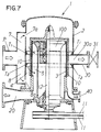
- numeral 30a designates a foreign substance discharge outlet of the foreign substance discharge passage 30, which is located, in height, between the first supply inlet 7a and the second supply inlet 8a and communicates with the first chamber 4.
- an opening and closing valve 31 for controlling a reject amount is disposed, and it is arranged such that an opening degree of the opening and closing valve 31 is adequately adjusted in accordance with the kind of the papermaking material or the like.
- An upper-side projecting member T 1 is located above the foreign substance discharge outlet 31, and is projected from an inner wall surface of the tank 2 to be circularly formed in the inner wall of the tank 2.
- the upper-side projecting member T 1 is provided to extend an entire periphery of the inner wall surface of the tank 2.
- the upper-side projecting member T 1 is located above the foreign substance discharge outlet 30a to narrow a passage or area P 1 in which the papermaking material supplied from the first supply inlet 7a flows toward the foreign substance discharge outlet 30a.
- the papermaking material which is supplied from the first supply inlet 7a to flow toward the lower part of the tank 2 and contains a lot of good fibers, and the papermaking material, which flows toward the foreign substance discharge outlet 30a and contains a lot of foreign substances, are prevented from colliding with each other, to thereby improve the screening efficiency.
- a lower-side projecting member T 2 is located below the foreign substance discharge outlet 30a, and is projected from the inner wall surface of the tank 2 to be formed circularly on the inner wall of the tank 2. More preferably, as shown in Figs. 6-8, the lower-side projecting member T 2 is provided to extend the entire periphery of the inner wall surface of the tank 2. As described above, the lower-side projecting member T 2 is disposed below the foreign substance discharge outlet 30a to narrow a passage or area P 2 in which the papermaking material supplied from the second supply inlet 8a flows toward the foreign substance discharge outlet 30a.
- the papermaking material which is supplied from the second supply inlet 8a to flow to the upper part of the tank 2 and contains a lot of good fibers, can be prevented from colliding with the papermaking material, which flows to the foreign substance discharge outlet 30a and mainly contains foreign substances, to thereby improve the screening efficiency.
- the upper-side projecting member T 1 and the lower-side projecting member T 2 may have sectional shapes shown in Figs. 9-11. However, more preferably, as shown in Fig. 9 and Fig. 10, the upper-side projecting member T 1 is inclined such that an amount projecting from the inner wall surface of the tank 2 is decreased toward the upper side of the tank 2, and the lower-side projecting member T 2 is inclined such that an amount projecting from the inner wall surface of the tank 2 is decreased toward the lower side of the tank 2.
- the papermaking material which is supplied from the first supply inlet 7a to flow toward the lower part of the tank 2 and contains good fibers, hits the upper-side projecting member T 1 as shown by an arrow in Fig. 9, and is guided to the upper side of the tank 2 so as to form an upper-side internal circulation flow in the upper side of the tank 2.
- the papermaking material which is supplied from the second supply inlet 8a to flow toward the upper part of the tank 2 and contains good fibers, hits the lower-side projecting member T 2 and is guided to the lower side of the tank 2 so as to form a lower-side internal circulation flow.
- the upper-side internal circulation flow and the lower-side internal circulation flow are formed, and screen efficiency and processing amount can be further improved.
- numeral 40 designates a passage for discharging heavy foreign substances in the tank 2, and an opening and closing valve, not shown, is provided in the passage 40 to adequately open or close the opening and closing valve, so that the heavy foreign substances are discharged outside the tank 2.
- the supply passage for supplying the papermaking material to the tank is provided plurally as the first supply passage and the second supply passage, and moreover, the second supply inlet of the second supply passage into the tank is positioned lower than the first supply inlet of the first supply passage into the tank.
- the flow distance of the papermaking material from the supply inlet for the papermaking material to the screen is shortened, so that the papermaking material is prevented from condensed.
- a concentration or condensation of the papermaking material passing through the screen is lowered, and the material passing resistance of the screen becomes small, so that the papermaking material passing through the screen is increased to thereby improve the processing amount.
- the condensation of the papermaking material which passes through the screen is lowered, clogging of the screen is reduced, so that the effect of separating foreign substances and good fibers can be improved.
- the first supply inlet is located higher than the openings at the uppermost part of the screen, and the second supply inlet is located lower than the opening at the lowermost part of the screen. Therefore, the papermaking material supplied from the first supply inlet does not directly hit the screen near the openings, so that damage of the screen due to the impact of the papermaking material can be prevented.
- the screen apparatus of the fourth aspect of the invention in addition to the effect of the first aspect of the invention, since a kind of a chamber, that is, reject chamber, for collecting foreign substances is formed between the upper-side projecting member and the lower-side projecting member, foreign substances entered between the upper-side projecting member and the lower-side projecting member are guided toward the foreign substance discharge outlet, so that the foreign substances can be efficiently collected and discharged through the foreign substance discharge outlet.
- a kind of a chamber that is, reject chamber
- the flow of the papermaking material, which is supplied from the second supply inlet to be flown toward the upper part of the tank and contains a lot of good fibers and the flow of the papermaking material, which is flown toward the foreign substance discharge outlet and contains a lot of foreign substances, collide with each other to lower screening efficiency.
- the upper-side projecting member is positioned above the foreign substance discharge outlet to narrow the passage or area in which the papermaking material supplied from the first supply inlet flows toward the foreign substance discharge outlet, so that the papermaking material, which flows toward the lower part of the tank and contains a lot of good fibers, is prevented from colliding with the papermaking material which flows toward the foreign substance discharge outlet and contains a lot of foreign substances.
- the lower-side projecting member is positioned below the foreign substance discharge outlet to narrow the passage or area in which the papermaking material supplied from the second supply inlet flows toward the foreign substance discharge outlet, so that the papermaking material, which flows toward the upper part of the tank and contains a lot of good fibers, is prevented from colliding with the papermaking material which flows toward the foreign substance discharge outlet and contains a lot of foreign substances. Accordingly, screening efficiency can be improved.
- the screen apparatus of the fifth aspect of the invention in addition to the effect of the fourth aspect of the invention, since the upper-side projecting member is inclined such that the amount projecting from the inner wall surface of the tank is decreased toward the upper side of the tank, the papermaking material which hits the upper-side projecting member is guided toward the upper side of the tank to form the upper-side internal circulation flow. Also, since the lower-side projecting member is inclined such that the amount projecting from the inner wall surface of the tank is decreased toward the lower side of the tank, the papermaking material which hits the first lower-side projecting member is guided toward the lower side of the tank to form the lower-side internal circulation flow in the lower side of the tank. Thus, in the tank, the upper-side internal circulation flow and the lower-side internal circulation flow are formed, and screening efficiency and the process amount can be improved.
Landscapes
- Engineering & Computer Science (AREA)
- Mechanical Engineering (AREA)
- Paper (AREA)
- Separation Of Solids By Using Liquids Or Pneumatic Power (AREA)
Applications Claiming Priority (4)
| Application Number | Priority Date | Filing Date | Title |
|---|---|---|---|
| JP10676098 | 1998-04-16 | ||
| JP10676098 | 1998-04-16 | ||
| JP15265098 | 1998-06-02 | ||
| JP15265098A JP3435346B2 (ja) | 1998-04-16 | 1998-06-02 | スクリーン装置 |
Publications (2)
| Publication Number | Publication Date |
|---|---|
| EP0950754A1 true EP0950754A1 (de) | 1999-10-20 |
| EP0950754B1 EP0950754B1 (de) | 2003-05-07 |
Family
ID=26446866
Family Applications (1)
| Application Number | Title | Priority Date | Filing Date |
|---|---|---|---|
| EP98120156A Expired - Lifetime EP0950754B1 (de) | 1998-04-16 | 1998-10-28 | Siebvorrichtung |
Country Status (8)
| Country | Link |
|---|---|
| US (1) | US6206204B1 (de) |
| EP (1) | EP0950754B1 (de) |
| JP (1) | JP3435346B2 (de) |
| KR (1) | KR100501107B1 (de) |
| CN (1) | CN1104525C (de) |
| CA (1) | CA2252317C (de) |
| DE (1) | DE69814344T2 (de) |
| TW (1) | TW409159B (de) |
Cited By (3)
| Publication number | Priority date | Publication date | Assignee | Title |
|---|---|---|---|---|
| EP1413671A1 (de) * | 2002-10-23 | 2004-04-28 | Aikawa Iron Works Co., Ltd. | Siebvorrichtung |
| US6883669B2 (en) | 2002-12-06 | 2005-04-26 | The University Of British Columbia | Multi-element airfoil for pulp screens |
| WO2021191137A1 (de) * | 2020-03-23 | 2021-09-30 | Klass Georg Jun | Anlage zur trennung suspendierter stoffe aus einer flüssigkeit mit einer filteranordnung nach art eines zyklonfilters |
Families Citing this family (10)
| Publication number | Priority date | Publication date | Assignee | Title |
|---|---|---|---|---|
| AT408997B (de) * | 2000-04-03 | 2002-04-25 | Andritz Ag Maschf | Sortierer für die papier-erzeugung und flügel für sortierer |
| CA2352414A1 (fr) * | 2001-07-05 | 2003-01-05 | Industries Fournier Inc. | Dispositif de controle et de retenue des gateaux dans un pressoir rotatif |
| US20030146171A1 (en) * | 2002-02-04 | 2003-08-07 | Karl-Heinz Herrmann | Liquid and solids separation apparatus and method with continuous cleaning using defferential pressure control |
| MX2007001426A (es) | 2004-08-09 | 2008-03-11 | Prime Solution Inc | Prensa de ventilador giratorio. |
| US7975854B2 (en) * | 2005-10-28 | 2011-07-12 | Prime Solution, Inc. | Rotary fan press |
| US8662315B2 (en) * | 2008-07-14 | 2014-03-04 | Prime Solution, Inc. | Rotary fan press |
| US9943786B2 (en) * | 2012-02-02 | 2018-04-17 | Aqseptence Group, Inc. | Screen intake cleaning system using variable flow of incompressible liquid |
| CN108677583B (zh) * | 2018-07-17 | 2023-09-05 | 玖龙纸业(重庆)有限公司 | 环形筛及其在压力筛中的应用 |
| CN116984242B (zh) * | 2023-08-04 | 2025-08-26 | 中交第三航务工程局有限公司 | 一种降低机制砂中石粉含量的过滤设备 |
| CN116750935B (zh) * | 2023-08-16 | 2023-11-03 | 山东中治环境工程设备有限公司 | 一种绿色环保的水环境治理设备 |
Citations (4)
| Publication number | Priority date | Publication date | Assignee | Title |
|---|---|---|---|---|
| FR2005590A1 (de) * | 1968-04-05 | 1969-12-12 | Voith | |
| EP0145365A2 (de) * | 1983-12-12 | 1985-06-19 | Uniweld Inc. | Rundsieb von vertikalem Überdrucktyp, mit Stockzufuhr auf verschiedenen, axial voneinander entfernten Positionen |
| US4744894A (en) * | 1986-06-30 | 1988-05-17 | Gauld W Thomas | Fibrous stock screening apparatus |
| WO1995011336A1 (en) * | 1993-10-18 | 1995-04-27 | Andritz Sprout-Bauer Ltd. | Rotary screening device |
Family Cites Families (5)
| Publication number | Priority date | Publication date | Assignee | Title |
|---|---|---|---|---|
| US4067800A (en) * | 1976-12-06 | 1978-01-10 | Ingersoll-Rand Company | Screening apparatus |
| US5096127A (en) * | 1990-08-22 | 1992-03-17 | Ingersoll-Rand Company | Apparatus for pressurized screening of a fibrous material liquid suspension |
| IT1249103B (it) * | 1991-03-21 | 1995-02-11 | Michele Guerinoni | Filtro continuo autopulentesi per fluidi viscosi |
| DE4135854A1 (de) * | 1991-10-31 | 1993-05-06 | J.M. Voith Gmbh, 7920 Heidenheim, De | Sortierer |
| JPH08209574A (ja) * | 1995-01-27 | 1996-08-13 | Aikawa Iron Works Co Ltd | 製紙用のスクリーンプレート |
-
1998
- 1998-06-02 JP JP15265098A patent/JP3435346B2/ja not_active Expired - Fee Related
- 1998-09-23 TW TW087115834A patent/TW409159B/zh not_active IP Right Cessation
- 1998-10-08 KR KR10-1998-0041961A patent/KR100501107B1/ko not_active Expired - Fee Related
- 1998-10-20 US US09/175,347 patent/US6206204B1/en not_active Expired - Fee Related
- 1998-10-28 EP EP98120156A patent/EP0950754B1/de not_active Expired - Lifetime
- 1998-10-28 DE DE69814344T patent/DE69814344T2/de not_active Expired - Lifetime
- 1998-11-03 CA CA002252317A patent/CA2252317C/en not_active Expired - Fee Related
- 1998-11-21 CN CN98122702A patent/CN1104525C/zh not_active Expired - Fee Related
Patent Citations (4)
| Publication number | Priority date | Publication date | Assignee | Title |
|---|---|---|---|---|
| FR2005590A1 (de) * | 1968-04-05 | 1969-12-12 | Voith | |
| EP0145365A2 (de) * | 1983-12-12 | 1985-06-19 | Uniweld Inc. | Rundsieb von vertikalem Überdrucktyp, mit Stockzufuhr auf verschiedenen, axial voneinander entfernten Positionen |
| US4744894A (en) * | 1986-06-30 | 1988-05-17 | Gauld W Thomas | Fibrous stock screening apparatus |
| WO1995011336A1 (en) * | 1993-10-18 | 1995-04-27 | Andritz Sprout-Bauer Ltd. | Rotary screening device |
Cited By (3)
| Publication number | Priority date | Publication date | Assignee | Title |
|---|---|---|---|---|
| EP1413671A1 (de) * | 2002-10-23 | 2004-04-28 | Aikawa Iron Works Co., Ltd. | Siebvorrichtung |
| US6883669B2 (en) | 2002-12-06 | 2005-04-26 | The University Of British Columbia | Multi-element airfoil for pulp screens |
| WO2021191137A1 (de) * | 2020-03-23 | 2021-09-30 | Klass Georg Jun | Anlage zur trennung suspendierter stoffe aus einer flüssigkeit mit einer filteranordnung nach art eines zyklonfilters |
Also Published As
| Publication number | Publication date |
|---|---|
| CA2252317C (en) | 2006-04-11 |
| KR19990081762A (ko) | 1999-11-15 |
| CN1104525C (zh) | 2003-04-02 |
| JP3435346B2 (ja) | 2003-08-11 |
| TW409159B (en) | 2000-10-21 |
| EP0950754B1 (de) | 2003-05-07 |
| KR100501107B1 (ko) | 2005-11-21 |
| CA2252317A1 (en) | 1999-10-16 |
| US6206204B1 (en) | 2001-03-27 |
| DE69814344D1 (de) | 2003-06-12 |
| CN1232103A (zh) | 1999-10-20 |
| DE69814344T2 (de) | 2004-03-25 |
| JP2000008287A (ja) | 2000-01-11 |
Similar Documents
| Publication | Publication Date | Title |
|---|---|---|
| US6206204B1 (en) | Screen apparatus | |
| US3912622A (en) | Screening machine with lights removal | |
| CA2003088C (en) | Screening device | |
| US6467188B1 (en) | Centrifugal pellet dryer apparatus | |
| US4919797A (en) | Screening apparatus for paper making stock | |
| US5884774A (en) | Papermaking screen | |
| EP0620033B1 (de) | Staubsammler mit Mitteln zum Sprühen von Wasser | |
| EP1882773B1 (de) | Siebvorrichtung | |
| US5186332A (en) | Paper stock screening apparatus having heavy rejects trap | |
| US5221437A (en) | Screening apparatus for paper making stock | |
| US6923329B2 (en) | Screen apparatus | |
| US2525701A (en) | Pulp screen | |
| EP1544349A1 (de) | Sortiervorrichtung für die Papierherstellung | |
| EP0298443B1 (de) | Methode und Vorrichtung zum Sauberhalten einer Sieb- oder Filteroberfläche | |
| US20070117706A1 (en) | Centrifugal separator | |
| US5048765A (en) | Paper material refining apparatus | |
| JPH05209389A (ja) | 紙料精選装置 | |
| EP1837437A1 (de) | Siebvorrichtung | |
| JPH05172463A (ja) | ペレット乾燥装置 | |
| JP2794234B2 (ja) | 縦形穀類選別機の未熟粒排出樋構造 | |
| KR20000007493U (ko) | 곡물색채선별기의 2차선별을 위한 순환구조 | |
| US20060000764A1 (en) | Pressurized screen for screening a fibrous suspension | |
| JP2002285489A (ja) | スクリーン装置 | |
| KR840000554B1 (ko) | 펄프 부유물(suspension)을 분리하기 위한 회전 스크리닝(screening)기계 | |
| JP2593382B2 (ja) | 縦型穀類選別機 |
Legal Events
| Date | Code | Title | Description |
|---|---|---|---|
| PUAI | Public reference made under article 153(3) epc to a published international application that has entered the european phase |
Free format text: ORIGINAL CODE: 0009012 |
|
| 17P | Request for examination filed |
Effective date: 19990811 |
|
| AK | Designated contracting states |
Kind code of ref document: A1 Designated state(s): DE ES FI FR GB IT SE |
|
| AX | Request for extension of the european patent |
Free format text: AL;LT;LV;MK;RO;SI |
|
| AKX | Designation fees paid |
Free format text: DE ES FI FR GB IT SE |
|
| 17Q | First examination report despatched |
Effective date: 20010330 |
|
| GRAH | Despatch of communication of intention to grant a patent |
Free format text: ORIGINAL CODE: EPIDOS IGRA |
|
| GRAH | Despatch of communication of intention to grant a patent |
Free format text: ORIGINAL CODE: EPIDOS IGRA |
|
| GRAA | (expected) grant |
Free format text: ORIGINAL CODE: 0009210 |
|
| AK | Designated contracting states |
Designated state(s): DE ES FI FR GB IT SE |
|
| REG | Reference to a national code |
Ref country code: GB Ref legal event code: FG4D |
|
| REF | Corresponds to: |
Ref document number: 69814344 Country of ref document: DE Date of ref document: 20030612 Kind code of ref document: P |
|
| PG25 | Lapsed in a contracting state [announced via postgrant information from national office to epo] |
Ref country code: SE Free format text: LAPSE BECAUSE OF FAILURE TO SUBMIT A TRANSLATION OF THE DESCRIPTION OR TO PAY THE FEE WITHIN THE PRESCRIBED TIME-LIMIT Effective date: 20030807 |
|
| PG25 | Lapsed in a contracting state [announced via postgrant information from national office to epo] |
Ref country code: ES Free format text: LAPSE BECAUSE OF FAILURE TO SUBMIT A TRANSLATION OF THE DESCRIPTION OR TO PAY THE FEE WITHIN THE PRESCRIBED TIME-LIMIT Effective date: 20030818 |
|
| ET | Fr: translation filed | ||
| PLBE | No opposition filed within time limit |
Free format text: ORIGINAL CODE: 0009261 |
|
| STAA | Information on the status of an ep patent application or granted ep patent |
Free format text: STATUS: NO OPPOSITION FILED WITHIN TIME LIMIT |
|
| 26N | No opposition filed |
Effective date: 20040210 |
|
| PGFP | Annual fee paid to national office [announced via postgrant information from national office to epo] |
Ref country code: DE Payment date: 20101022 Year of fee payment: 13 |
|
| PGFP | Annual fee paid to national office [announced via postgrant information from national office to epo] |
Ref country code: IT Payment date: 20101026 Year of fee payment: 13 Ref country code: GB Payment date: 20101021 Year of fee payment: 13 |
|
| PGFP | Annual fee paid to national office [announced via postgrant information from national office to epo] |
Ref country code: FI Payment date: 20111013 Year of fee payment: 14 Ref country code: FR Payment date: 20111103 Year of fee payment: 14 |
|
| GBPC | Gb: european patent ceased through non-payment of renewal fee |
Effective date: 20121028 |
|
| REG | Reference to a national code |
Ref country code: FR Ref legal event code: ST Effective date: 20130628 |
|
| PG25 | Lapsed in a contracting state [announced via postgrant information from national office to epo] |
Ref country code: DE Free format text: LAPSE BECAUSE OF NON-PAYMENT OF DUE FEES Effective date: 20130501 Ref country code: GB Free format text: LAPSE BECAUSE OF NON-PAYMENT OF DUE FEES Effective date: 20121028 |
|
| REG | Reference to a national code |
Ref country code: DE Ref legal event code: R119 Ref document number: 69814344 Country of ref document: DE Effective date: 20130501 |
|
| PG25 | Lapsed in a contracting state [announced via postgrant information from national office to epo] |
Ref country code: IT Free format text: LAPSE BECAUSE OF NON-PAYMENT OF DUE FEES Effective date: 20121028 Ref country code: FI Free format text: LAPSE BECAUSE OF NON-PAYMENT OF DUE FEES Effective date: 20121028 Ref country code: FR Free format text: LAPSE BECAUSE OF NON-PAYMENT OF DUE FEES Effective date: 20121031 |